
 
     |
| LS4 / F40 swap - fieroguru (Page 24/216) |

|
fieroguru
|
APR 30, 09:45 PM
|
|
| quote | Originally posted by dobey:
Isn't #8 on the other side, and #1 the one nearest the passenger side strut tower? I think you need to move that sensor to the other side if you want the #8 cylinder. |
|
Nope. For GM V configuration applications, #1 is the cylinder closest to the balancer with 1 bank always being slightly ahead of the other. For V8's the DS (or front bank in fiero speak) has cylinder #1 and the passenger or rear bank has cylinder #8. Where this gets confusing is on the 60 degree V6 the PS bank is further forward, giving it cylinder #1.
|
|
|
|
blander66
|
MAY 01, 12:14 AM
|
|
For the temp sensor you can get a 3 wires sensor that will work for both the ECM and the Temp gague in the dash, I am running this sensor in a truck i put a ls in.
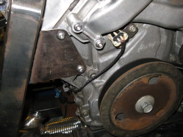
| quote | Originally posted by fieroguru:
I am planning to drill/tap the coolant sensor hole by cyl #1 for the temp sender for the gauge. Still need to order a new fiero temp sensor.
|
|
[This message has been edited by blander66 (edited 05-01-2011).]
|
|
|
|
fieroguru
|
MAY 01, 07:40 AM
|
|
| quote | Originally posted by blander66:
For the temp sensor you can get a 3 wires sensor that will work for both the ECM and the Temp gague in the dash, I am running this sensor in a truck i put a ls in.
|
|
Do you have a part # or application for the sender?
|
|
|
|
fieroguru
|
MAY 01, 08:32 AM
|
|
| quote | Originally posted by blander66:
For the temp sensor you can get a 3 wires sensor that will work for both the ECM and the Temp gague in the dash, I am running this sensor in a truck i put a ls in.
|
|
Found it:
3 wire LS1 temp sender GM # 12551708, application 1998 Camaro w/ LS1, pigtail is the same as the TPS sensor on the fiero 2.5 and later model applications.
The bottom wire is for the gauge.
Only downside to using this 3 wire setup is I will loose the temp light, but the gauge is much more important anyways. I like the idea of 1 less sensor.[This message has been edited by fieroguru (edited 05-01-2011).]
|
|
|
|
dobey
|
MAY 01, 09:52 AM
|
|
| quote | Originally posted by fieroguru:
Nope. For GM V configuration applications, #1 is the cylinder closest to the balancer with 1 bank always being slightly ahead of the other. For V8's the DS (or front bank in fiero speak) has cylinder #1 and the passenger or rear bank has cylinder #8. Where this gets confusing is on the 60 degree V6 the PS bank is further forward, giving it cylinder #1. |
|
Ah, right. Guess I've been spending too much time with the V6s.
|
|
|
|
fieroguru
|
MAY 01, 07:41 PM
|
|
Probably my least favorite part of any swap... wiring.
Started with the cam sensor, wrapping around the rear of the engine picking up the O2 sensor, oil level sensor, bank 2 knock, crank position sensor, VSS and coolant temp sensor (still needs to be added). Then up over the bellhousing where I have the first 4 coils added to the harness (ignore the yellow wire ties... they are just temporary).
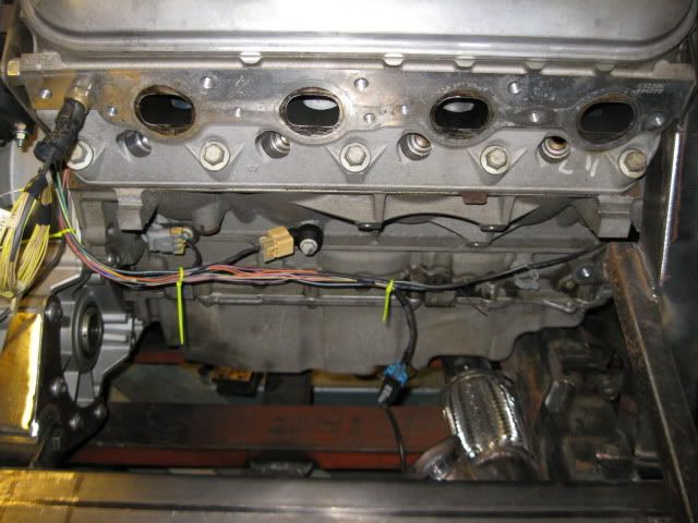
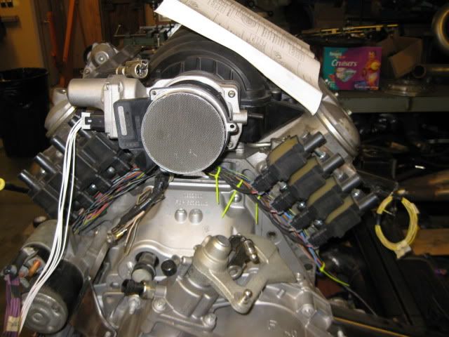
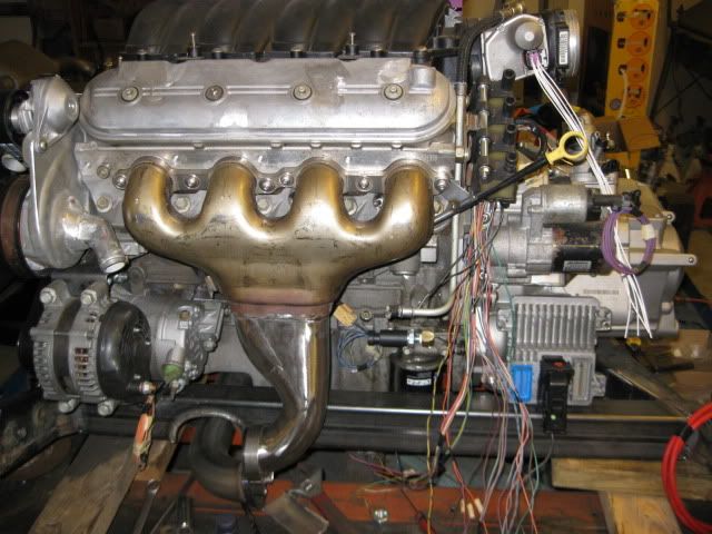
Still a lot more wires to add... (wide band o2, 4 more coils, 8 injectors, DOD connector, oil pressure sender, reverse lights, DWB throttle body, MAF, MAP sensor and starter. Then I will start with the Alternator, AC, bank 1 knock, oil pressure sender (gauge) and combine with the main harness. The car does not have a 500 connector on the passenger strut tower, so there is no need for any wires to cross over the accessory belt.
The ECM is shown in the approximate location it will be mounted (let the flood gates open to tell me how stupid it is to put it there!). I want the drivetrain to be almost entirely self-contained with the bare minimum of connections to the chassis, so the ECM needs to be mounted on the cradle somewhere away from excessive heat and I really do not want to see it (or the wires going to it).[This message has been edited by fieroguru (edited 05-01-2011).]
|
|
|
|
fieroguru
|
MAY 02, 05:36 PM
|
|
|
Sold the 4T65e-HD this afternoon for $575... not bad considering I purchased the engine/transmission combo for $1000. Now I need to decide on which wide band to get...
|
|
|
|
aaronkoch
|
MAY 02, 06:34 PM
|
|
I don't see any problems at all putting it there.. the connectors are sealed, and it will have really decent airflow there & stay nice and cool.
------------------
Currently in the middle of my 88 + 3800NA swap
|
|
|
|
fieroguru
|
MAY 05, 09:25 PM
|
|
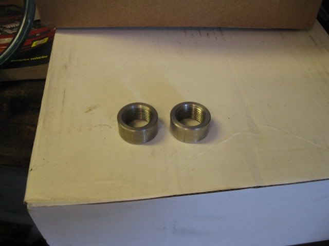
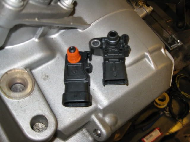
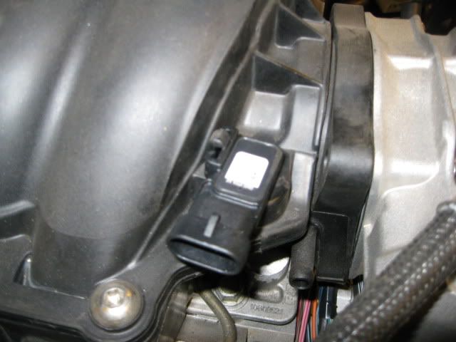
The stainless o2 bungs came in today, as well as the LS2 map sensor (LS4 one will not fit the LS2 intake):
Purchased an Innovate LC-1 wide band with gauge, MAF pigtail, and 3 wire temp sender... waiting on them to come in.
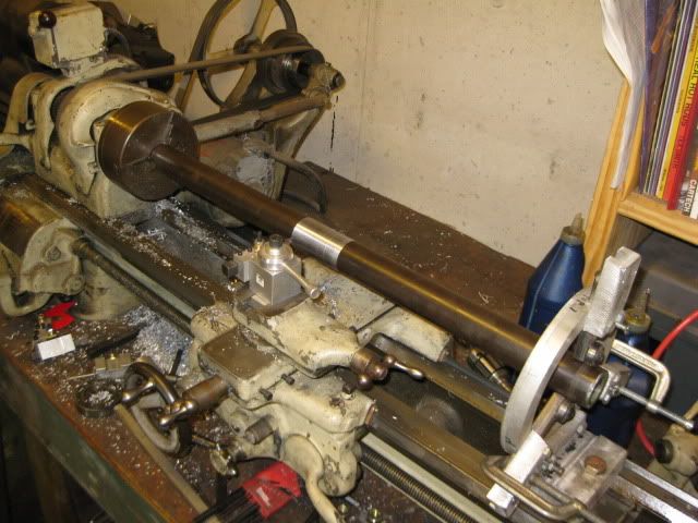
So I went ahead and turned down the shaft that will slide inside the Saab intermediate shafts to lengthen them. About 12" length was turned down to the proper size:
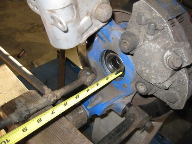
Then mocked up the passenger side suspension to figure out how much longer the intermediate shaft needed to be.

With the lateral links approximately level (they will actually be pointed up due to its lowered stance) and a saab intermediate shaft in the transmission, the distance from the back of the wheel bearing (where the outer CV seats) to the end of the intermediate shaft was measured = 19 1/4":
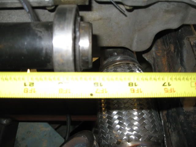
With that I went and measured the fully compressed and fully extended length (from base of bearing on CV to edge of seal surface on tripod - not the overall compressed length as shown in most catalogs) of the G6 F40 Driver side axle: fully compressed 16 7/8", fully extended (edge of rollers at edge of tripod cage) = 18 1/4", midpoint = 17 9/16
So to center the tripod at stock ride height with the G6 F40 driver side axle the intermediate shaft needs to be 1 11/16" longer.
I will probably start with the intermediate shaft extended 1 7/8" and tack the two tubes together w/o the inner sleeve and then do test fit and cycle the suspension to check for binding. If I need to make it shorter, that would be easy at that point, making it longer... not so much, so I will start with it slightly longer to begin with.
Changing gears... now if you are going to be chopping up 2 saab intermediate shafts, you could assemble two male ends vs keeping the current 1 male and 1 female setup. The only issue doing this, is the male end of the intermediate shaft is shorter than a normal tripod spline section and is missing the snap ring that retains it within the transmission (it didn't need one with the intermediate shaft support bearing ensuring the intermetiate shaft stays properly seated in the differential).
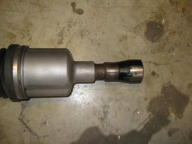
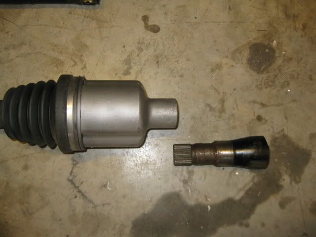
A resourceful person could install a bolt on extension to the male end of the intermediate shaft to accommodate a retaining ring (doesn't seem much force) and make this male/male intermediate shaft setup work.
|
|
|
|
Ruffy
|
MAY 06, 08:19 PM
|
|
|
I see your still building on my car. make sure you have it done by this week! i wana drive it lol.
|
|
|
|