|
| Trinten's SBC/F23 build - The work has begun! (Page 23/76) |

|
Trinten
|
OCT 20, 06:07 PM
|
|
LOL,
When it comes to the A/C... as long as it's functional I'm happy. Besides, buried down there, it'd get so dirty and such, I don't worry about it. I don't even know if there are better (or smaller) compressors out there, or if it'd be worth it to slap a smaller one in there.
|
|
|
|
fieroguru
|
OCT 20, 07:00 PM
|
|
| quote | Originally posted by Trinten:
That looks awesome! |
|
Glad you like how it is shaping up!
| quote | Originally posted by ltlfrari:
It looks awesome but I have to laugh. I keep seeing pics of this wonderful beast of an engine and there, tucked away under it is the same tired ol' crummy a/c compressor without so much as a lick of paint to make it look 'nice'.
|
|
I did scrape/knock about 1/4" of grease/grime off the compressor, does that count? However, the picture of the end does show that the compressor is still in need of some cleaning.
This is just the mockup stage. Once everything has been fabricated/test fitted, then it all comes apart for further cleaning/painting. However, painting the A/C compressor wasn't in the scope of work, and I hadn't plan on doing much more to it than brush it off.
| quote | Originally posted by ltlfrari:
Truly fabulous work though.
|
|
Thanks![This message has been edited by fieroguru (edited 10-20-2013).]
|
|
|
|
fieroguru
|
OCT 23, 08:31 PM
|
|
|
|
|
fieroguru
|
OCT 25, 08:53 PM
|
|
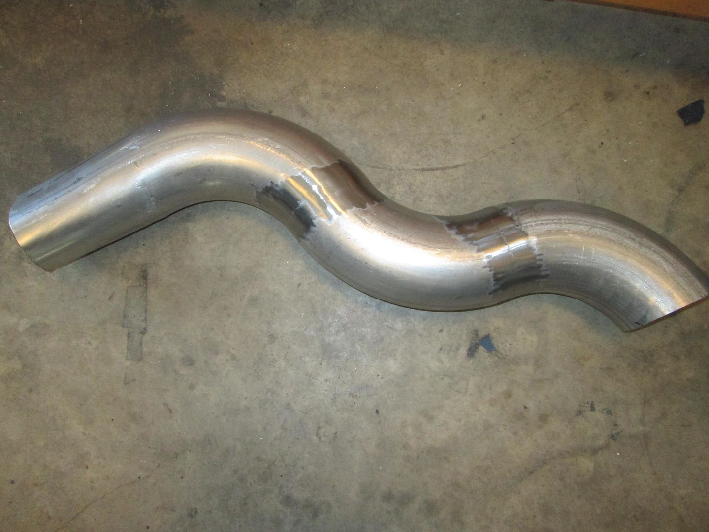
Trimmed down the oil dipstick tube. Now I just need to remove the roll pin that secured the top, drill a new hole in the dipstick metal, then cut the excess off, then reassemble.
Put the drivetrain back into the chassis for hopefully the last test fit. I plan to connect all the hoses, cables, air intake, water pump and thottle before pulling it back out again for cleaning/painting and the engine bay detailing.
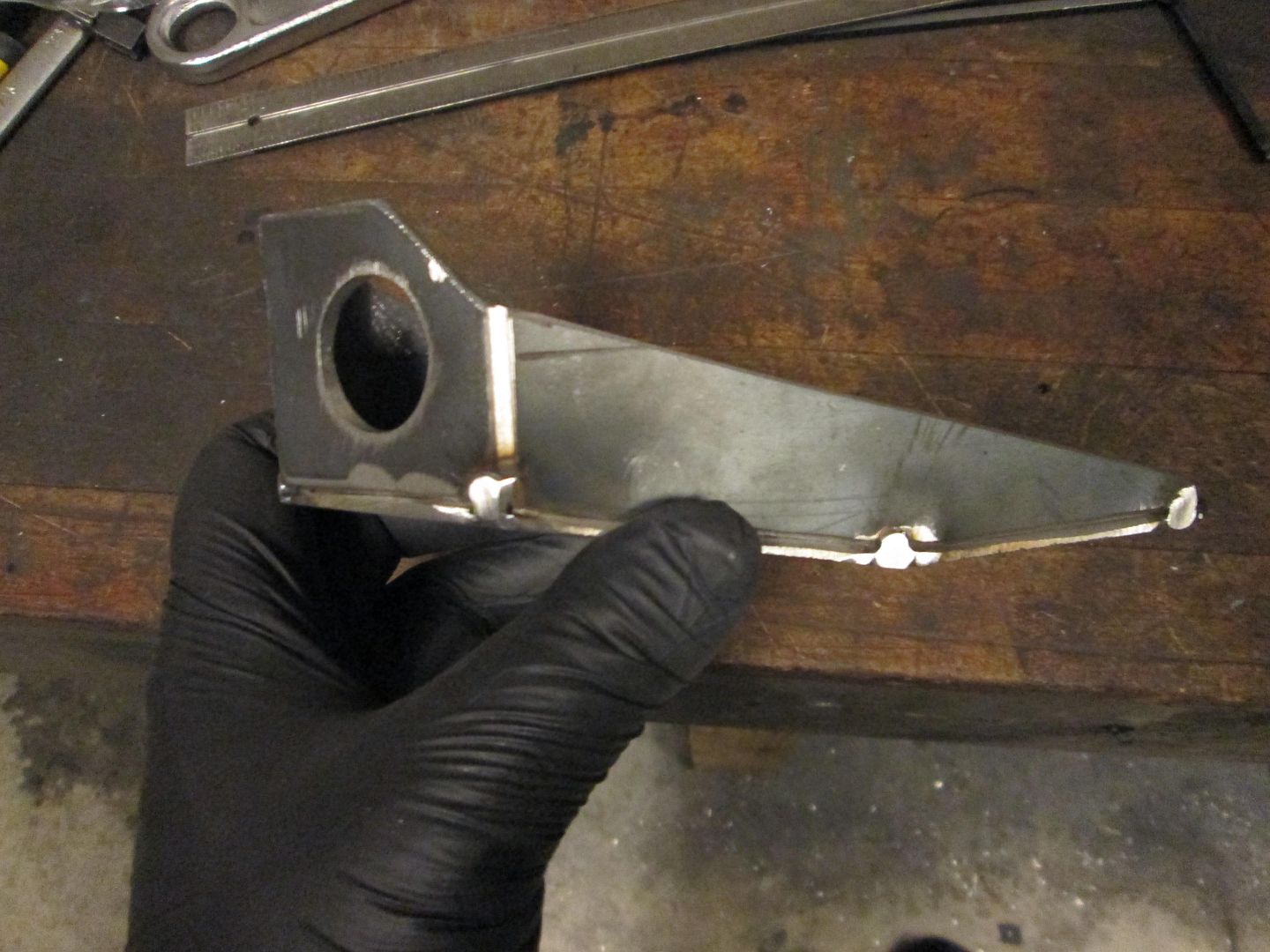
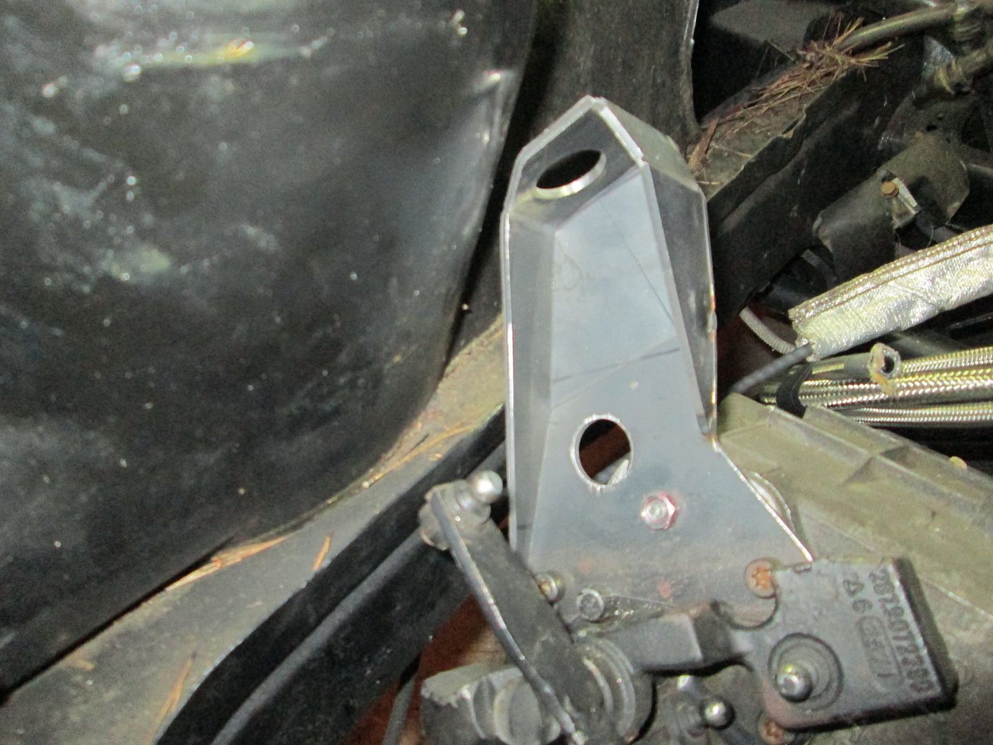
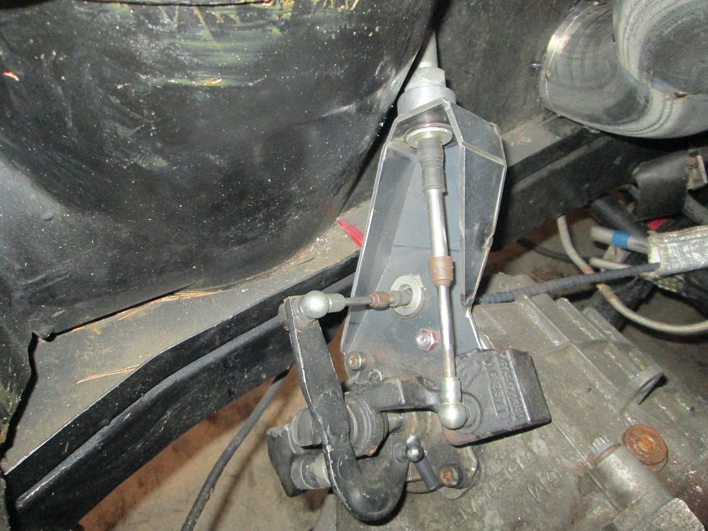
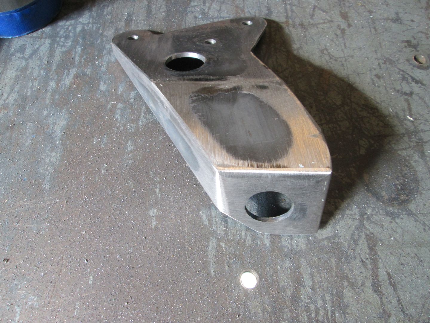
The first minor issue the test fit revealed was I needed to tweak the shape of the shifter bracket. Since it didn't fit as tacked together, I cut the spot welds and tested the base place and it fit just fine:

Then I slid the top part of the bracket as close to the strut tower and marked where it needed to be trimmed:
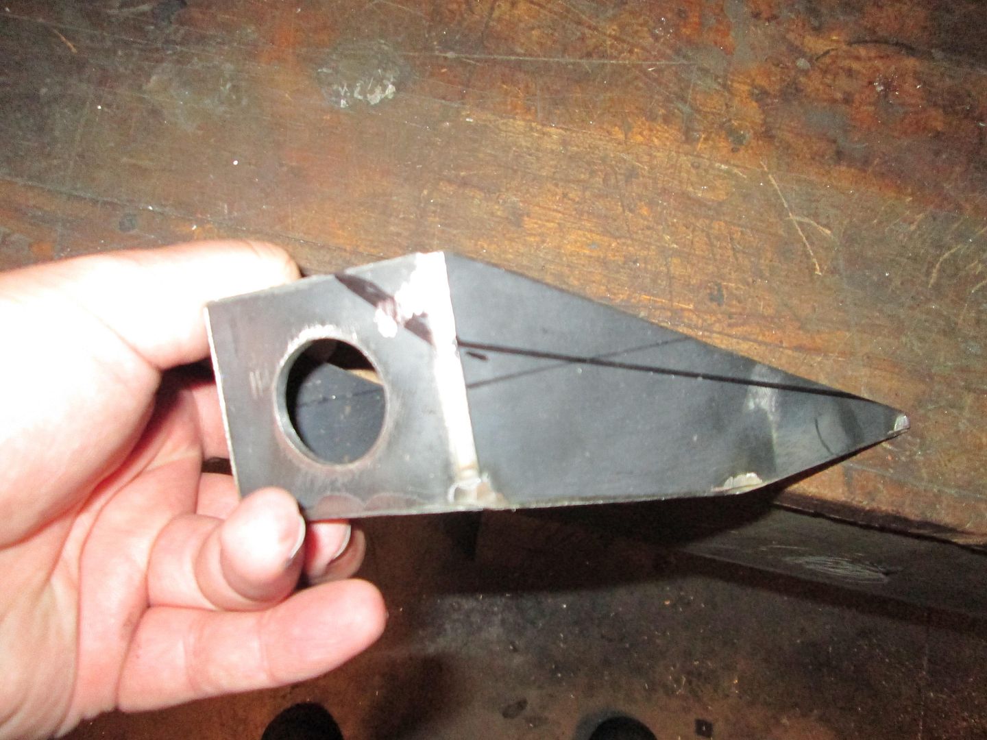
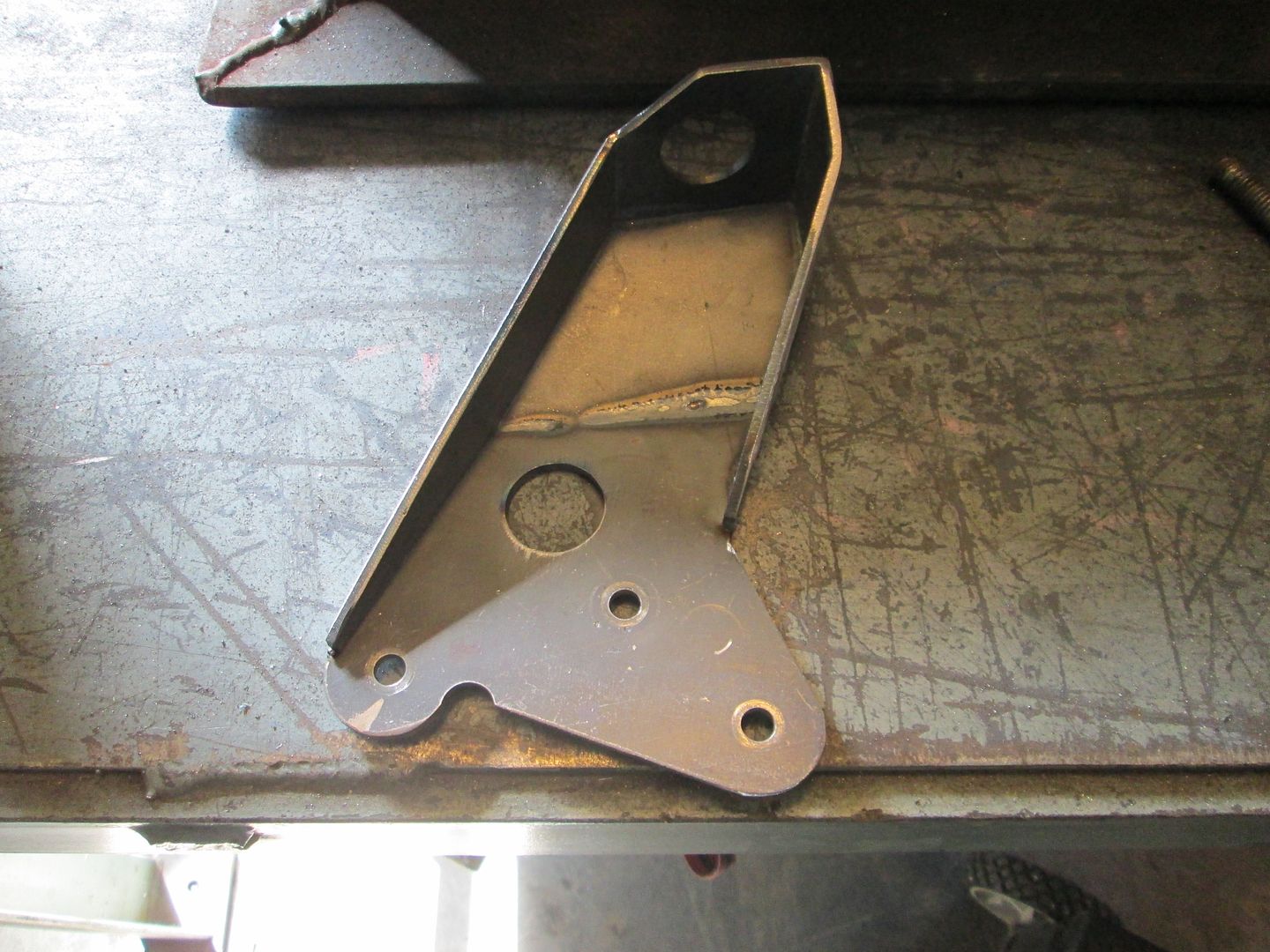
Trimmed, smoothed, tacked and ready to go back in:

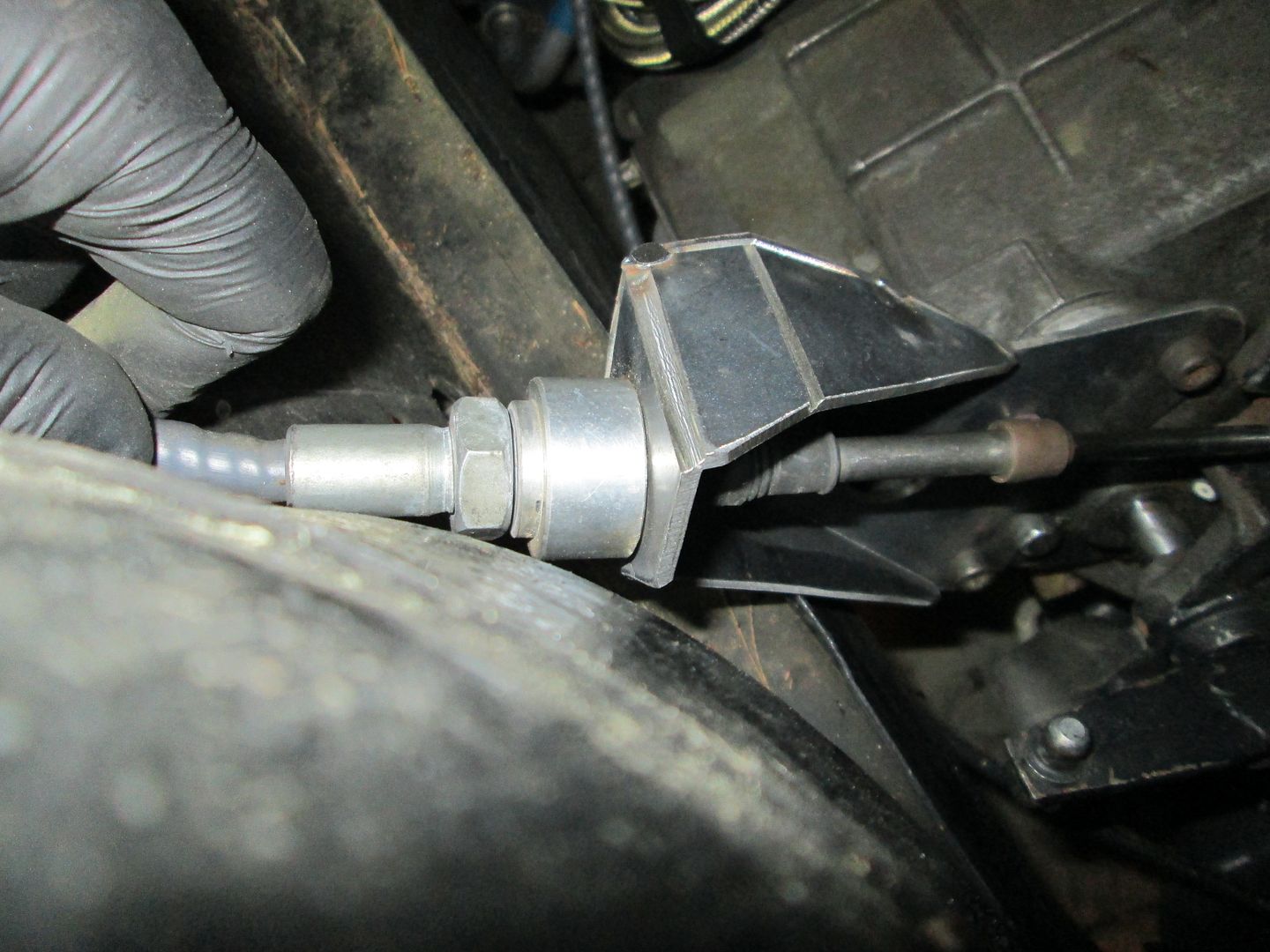
The coolant fittings for the water pump fit like they should:
The heater hose will go down in the small space between the belt and the passenger frame rail. It will be clamped to the passenger frame rail to keep it away from the belt:
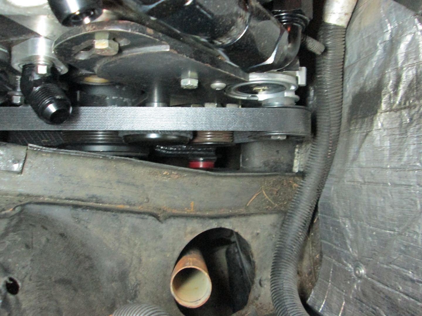
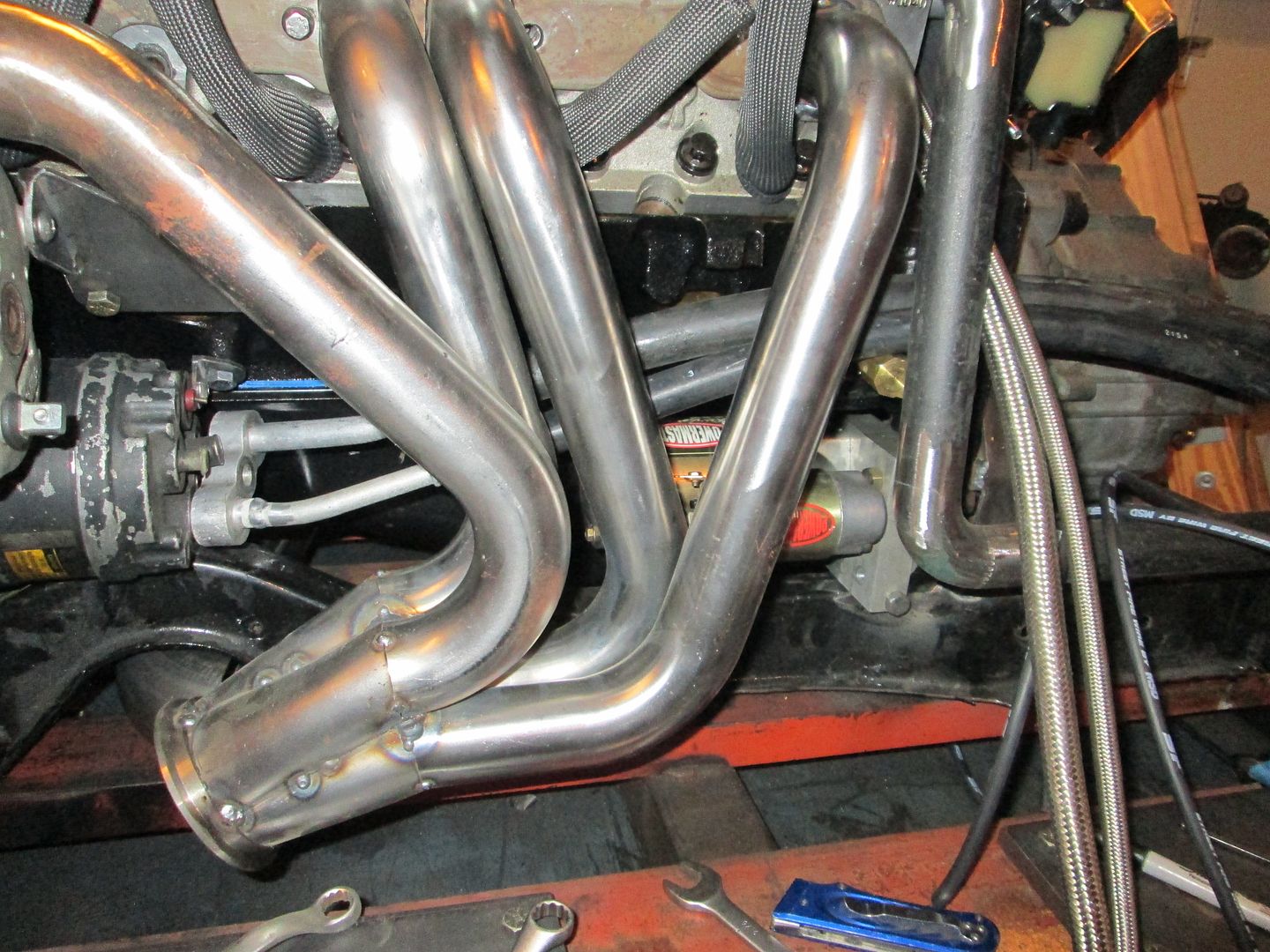
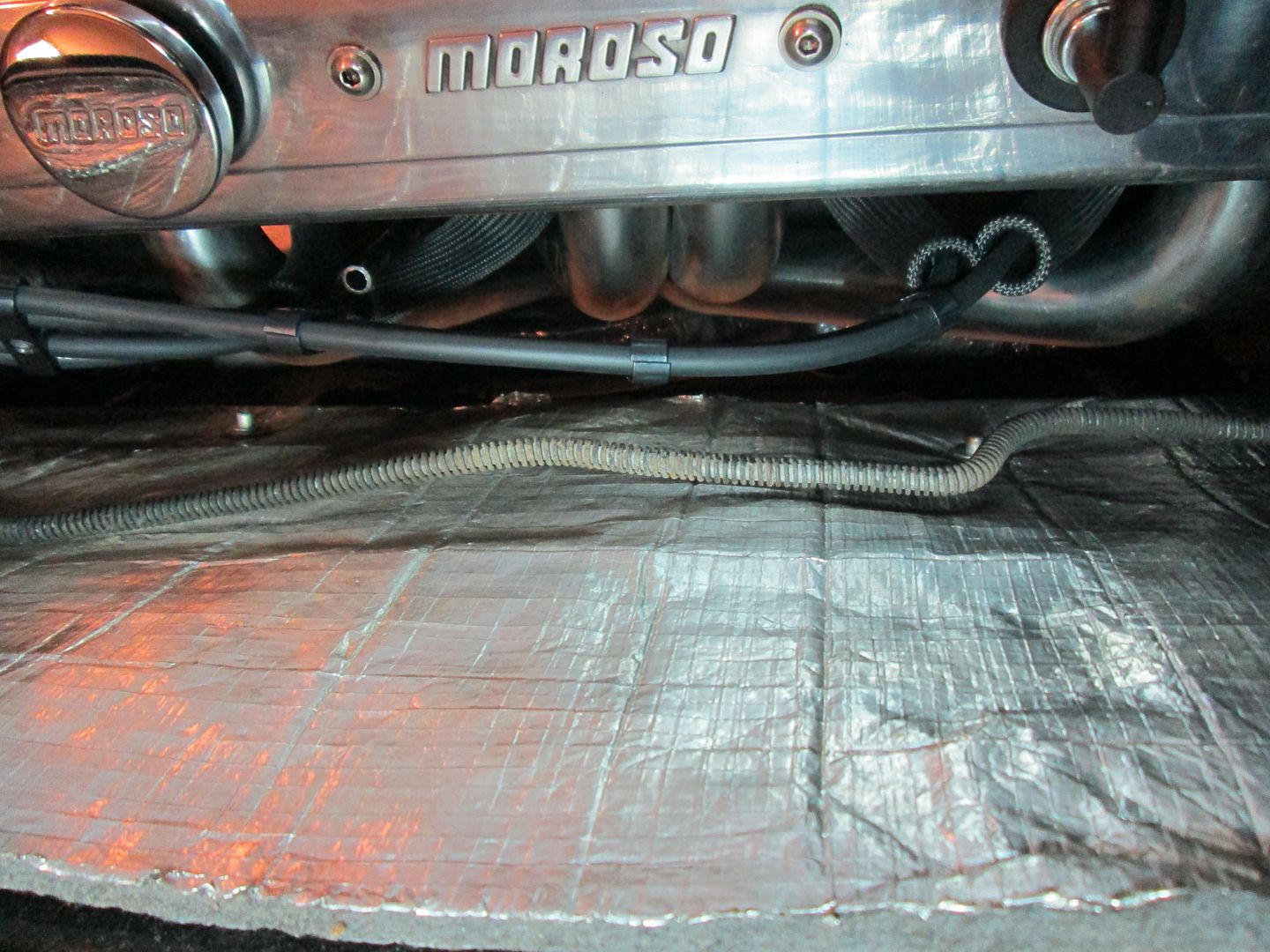
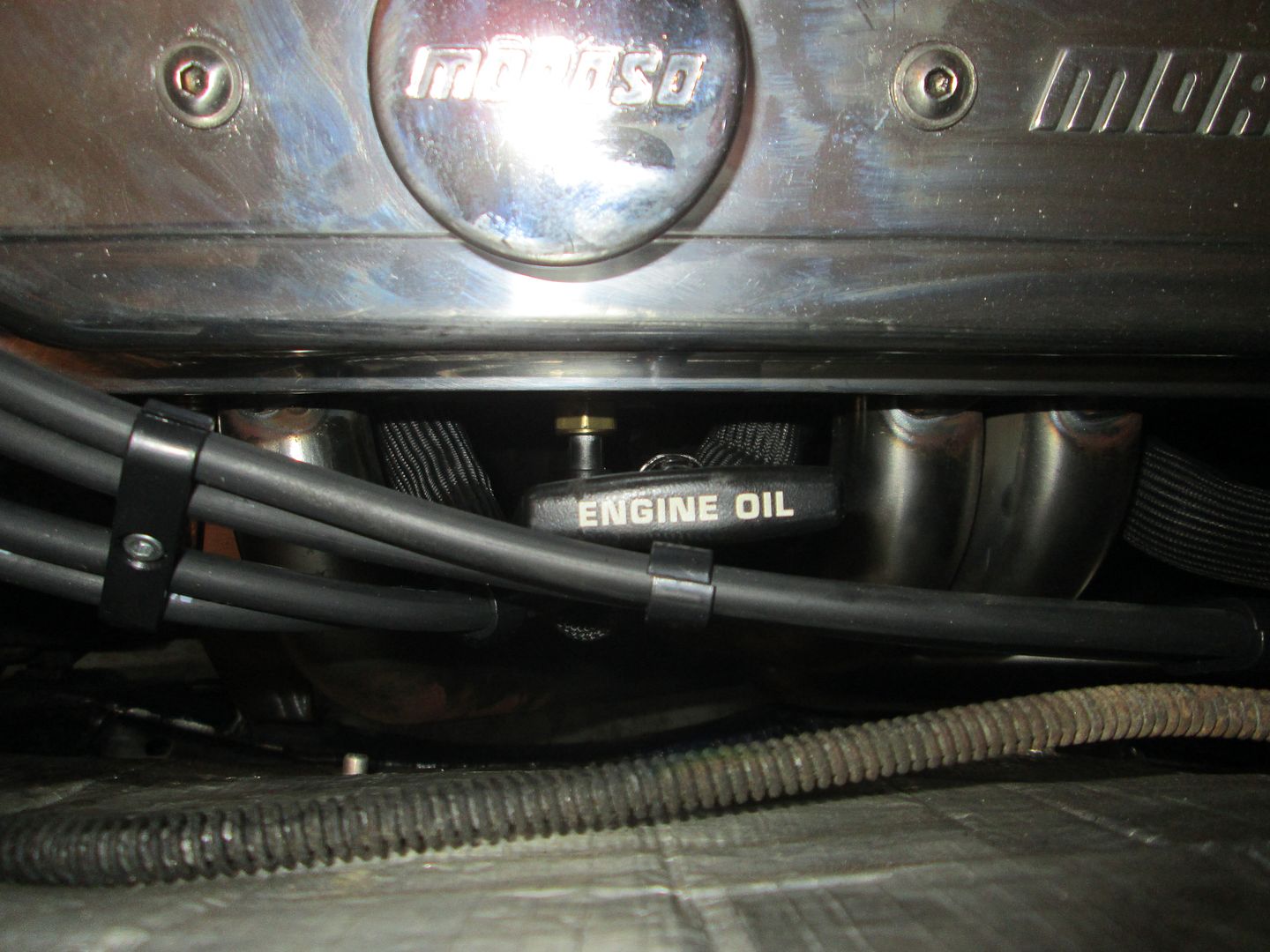
The rear header clears everything in the rear and the front one has even more room:
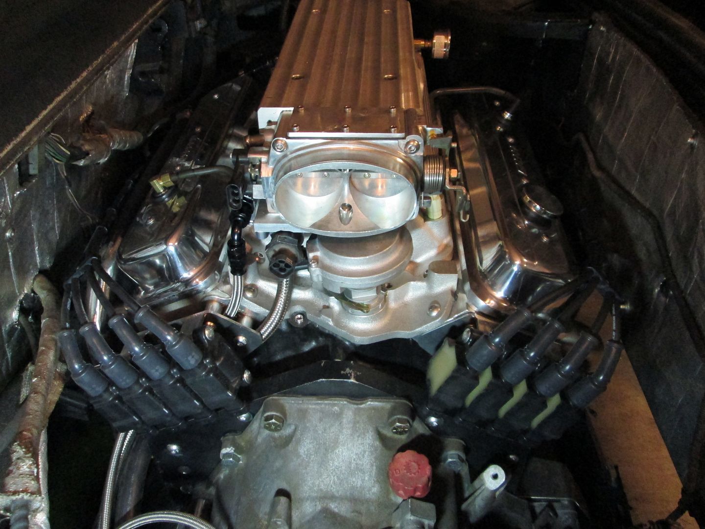
Here is a pic of the plug wires:
|
|
|
|
CowsPatoot
|
OCT 26, 02:27 AM
|
|
| quote | Originally posted by fieroguru:
|
|
That looks angry...I like it.
|
|
|
|
Trinten
|
OCT 26, 11:23 AM
|
|
Looking fantastic!
Sorry that the new shifter bracket gave you so much trouble though :/
The result was definitely nice. Thank you for the work you put into it.
|
|
|
|
fieroguru
|
OCT 26, 07:54 PM
|
|
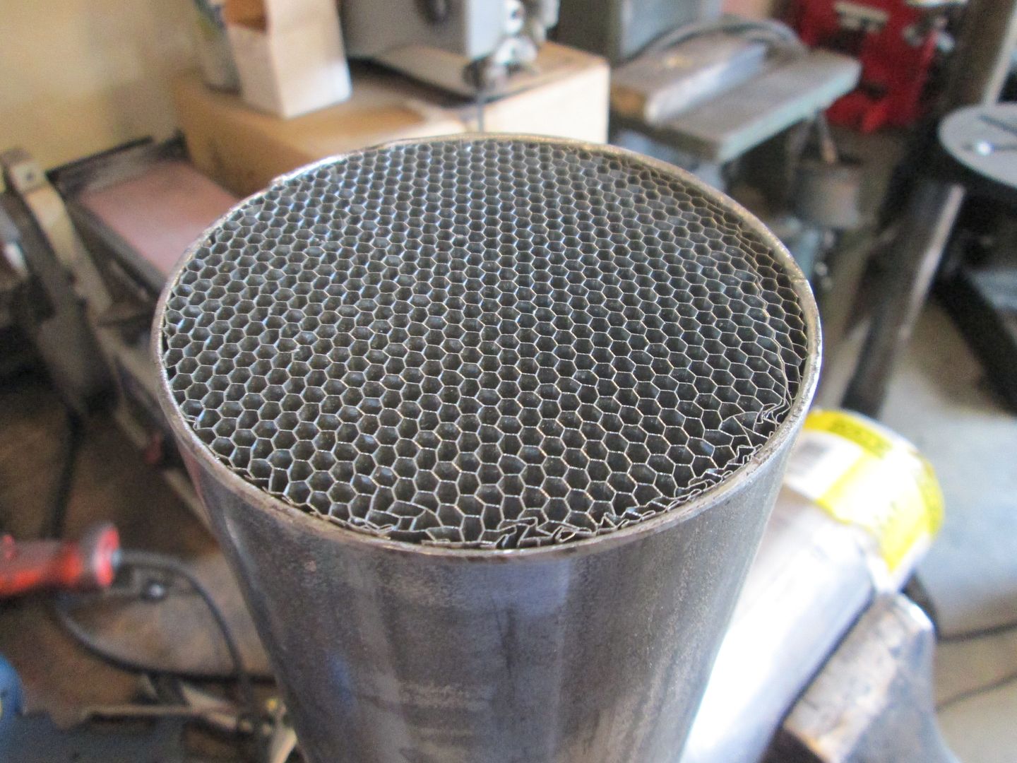
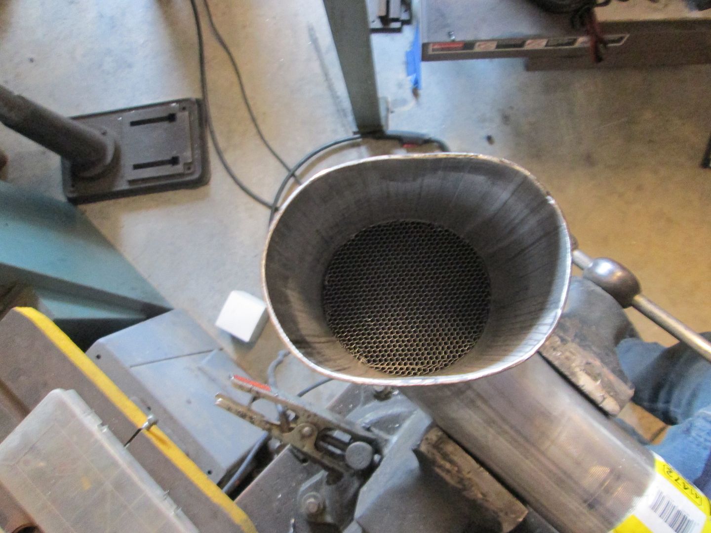
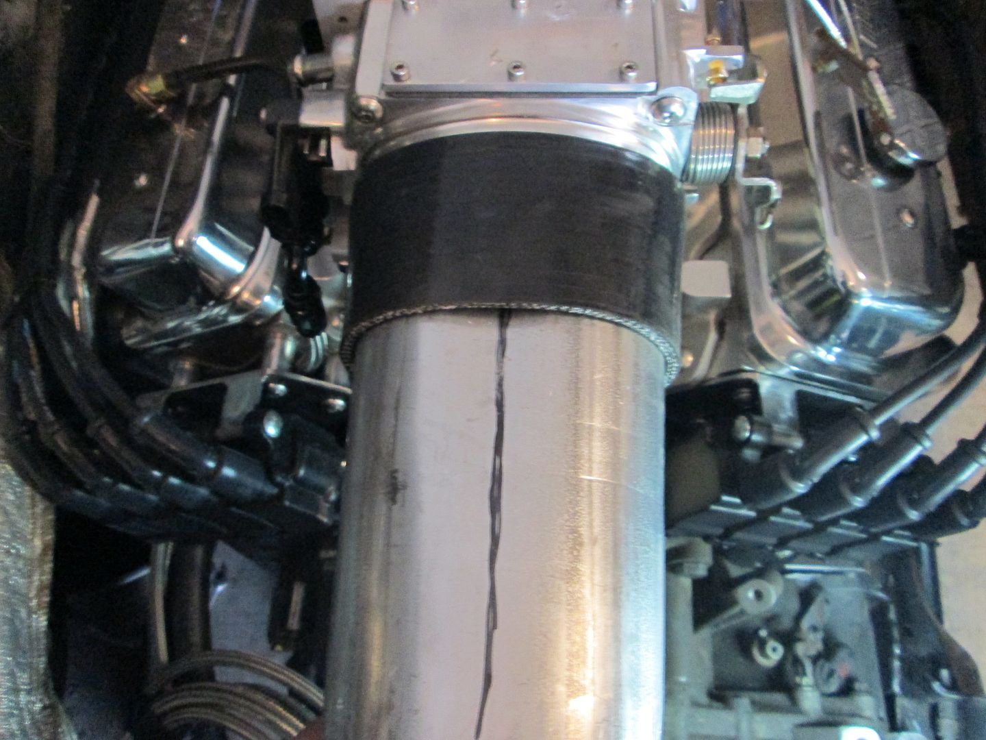
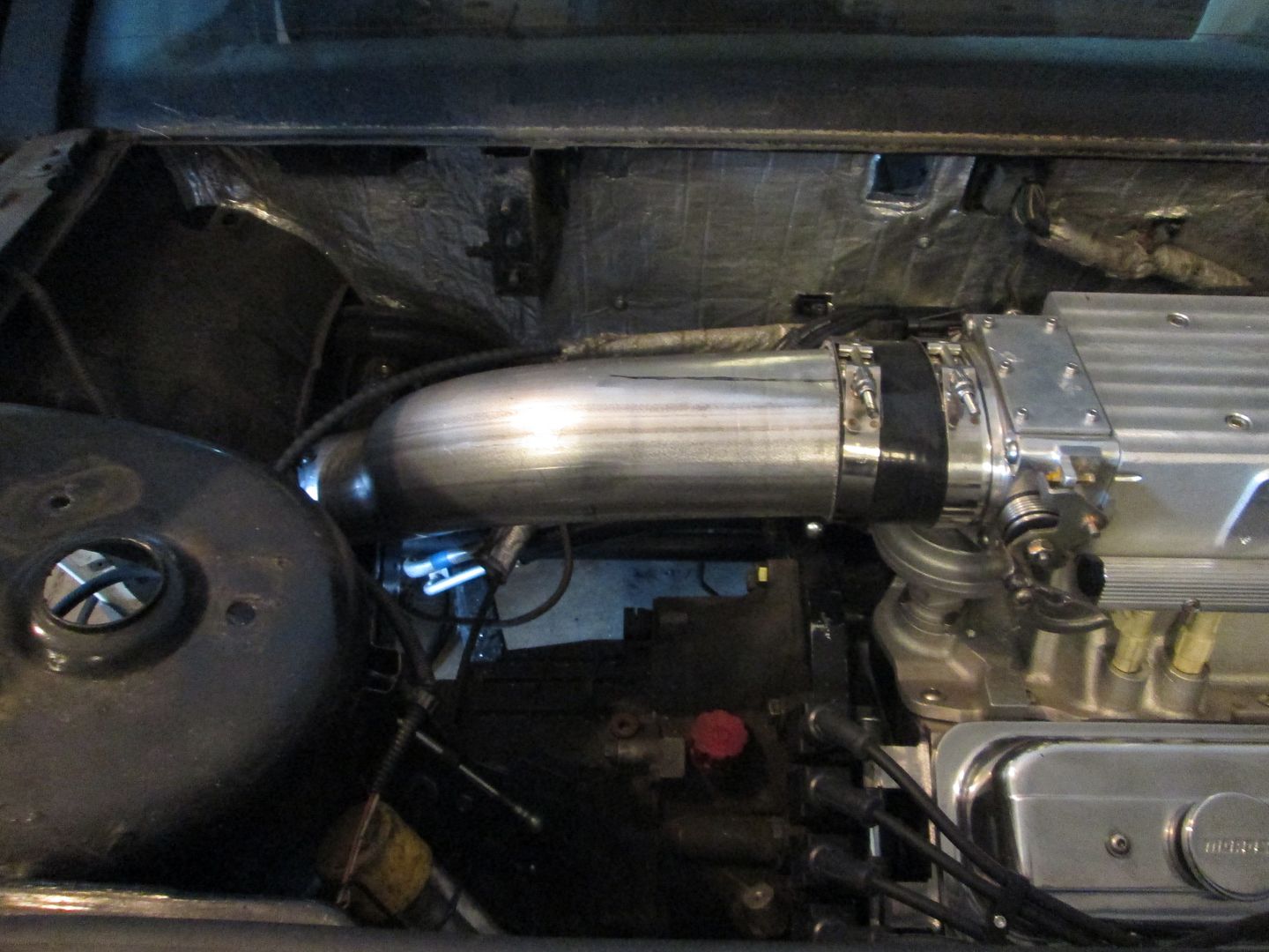
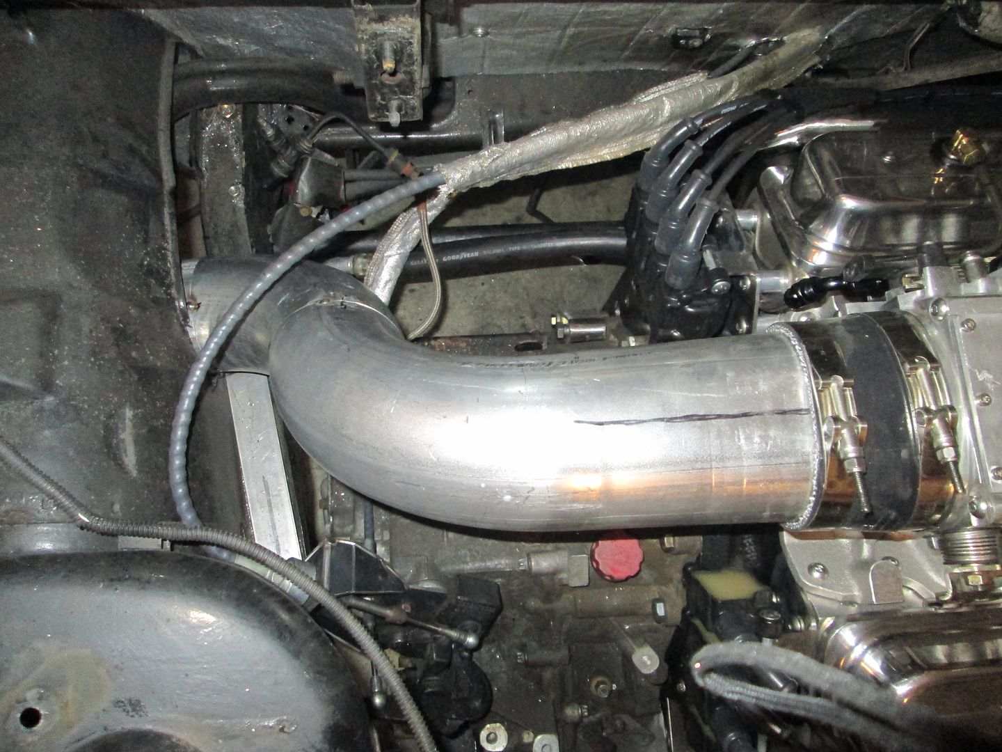
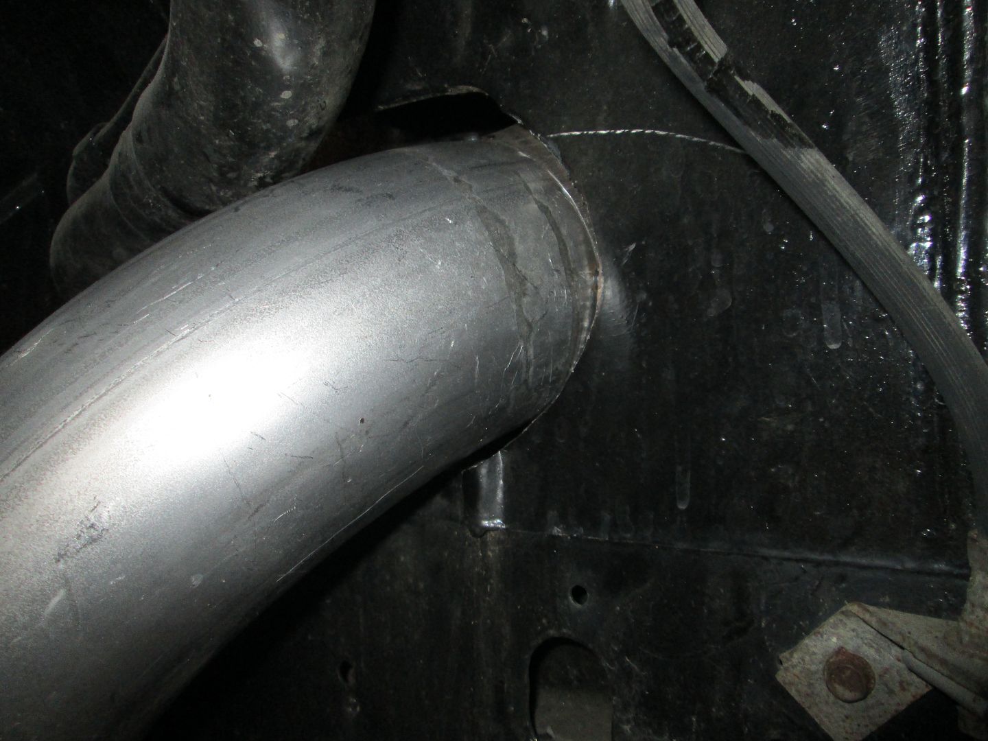
Started fabbing up the 4" cold air intake.
Step 1 was press in the honeycomb mesh for the LS7 MAF:
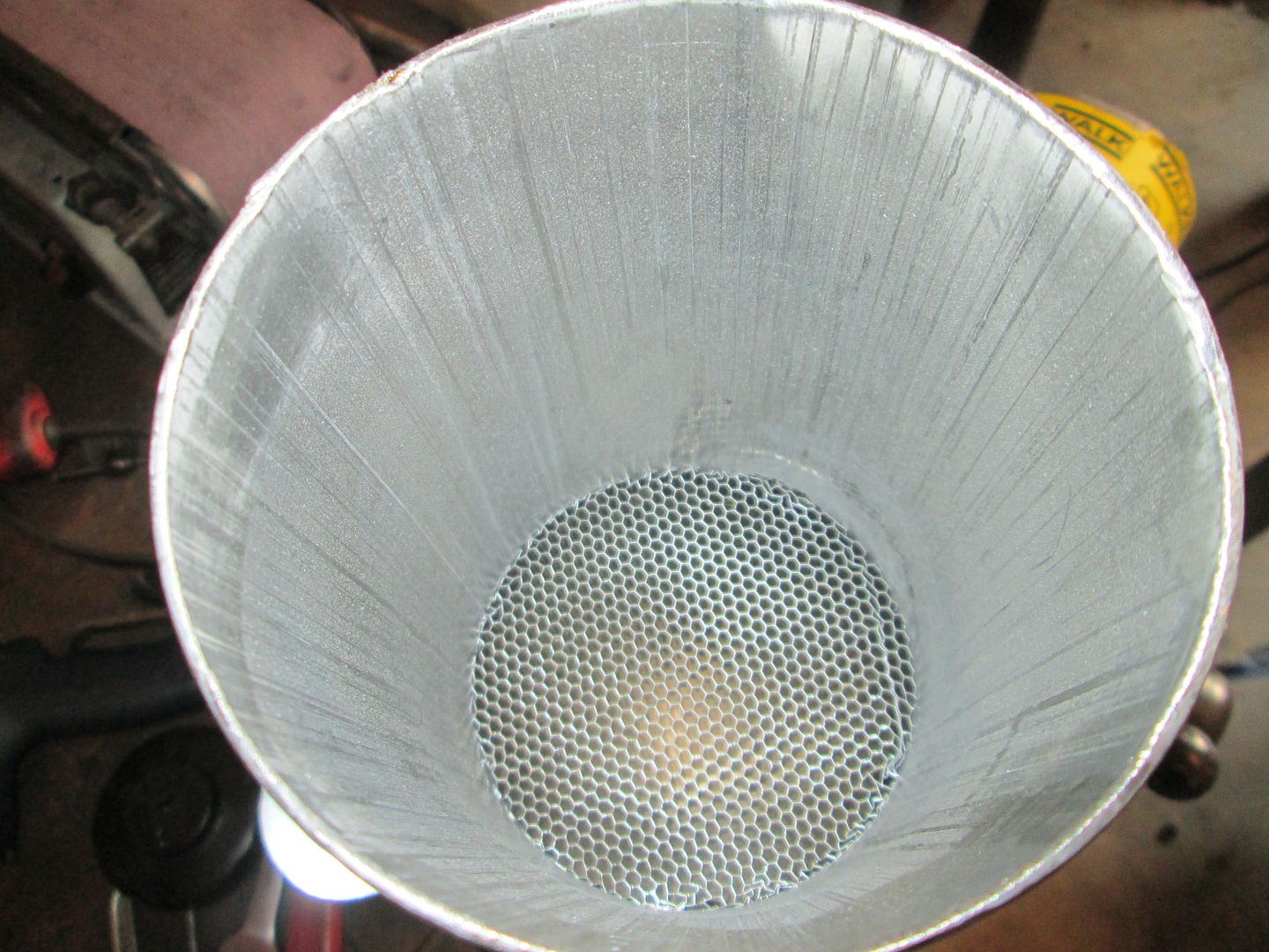
Compressed the end so the tube goes from round to oval so it will be closer to the shape of the TPI throttle body:
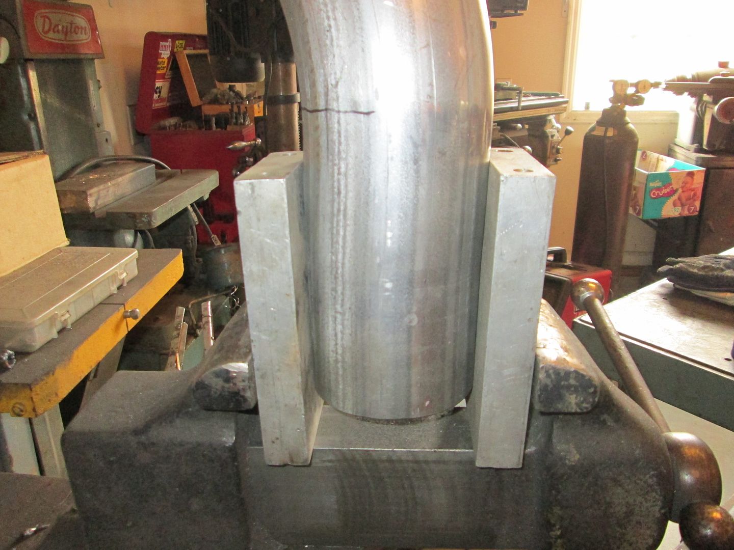
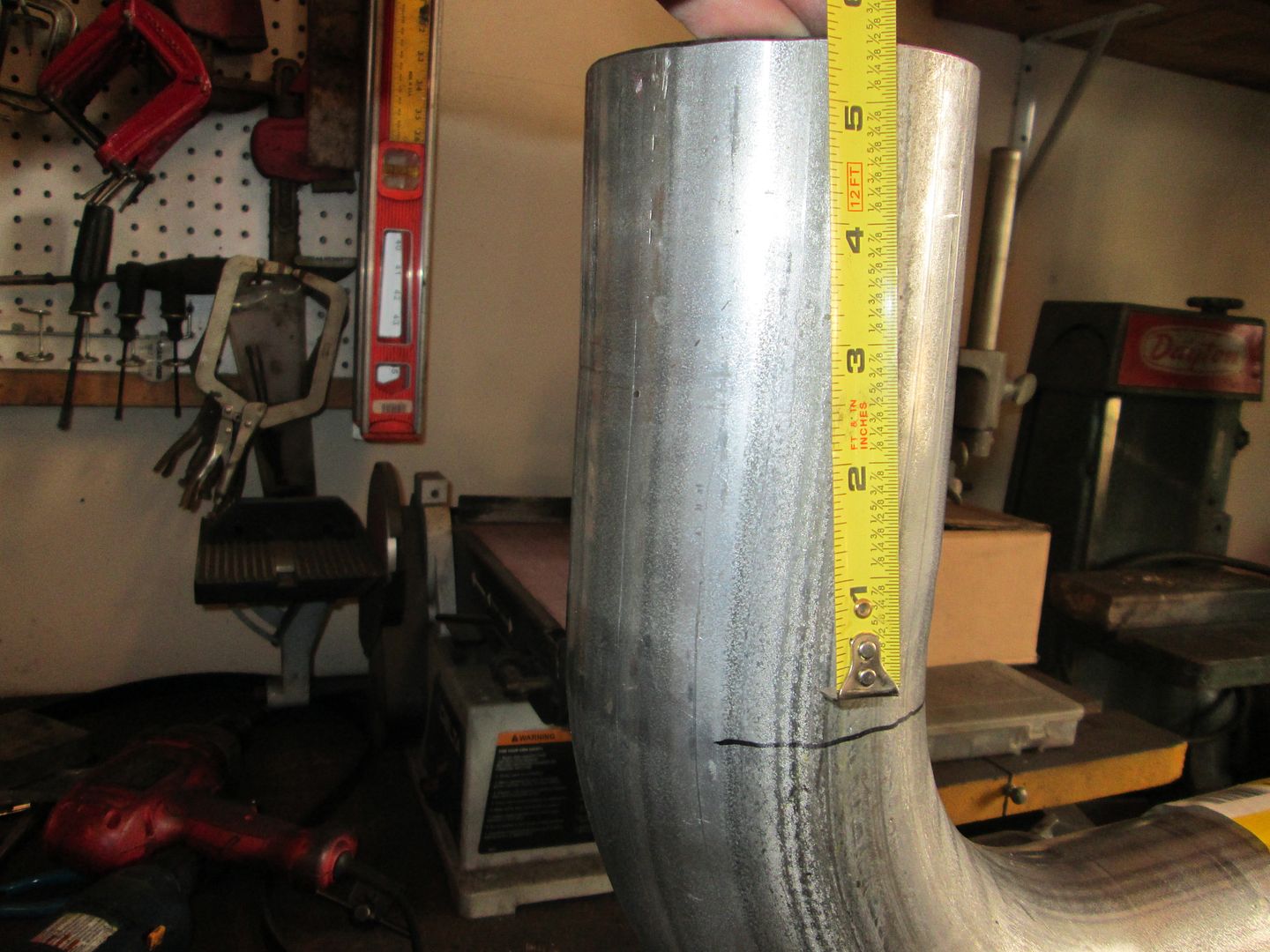
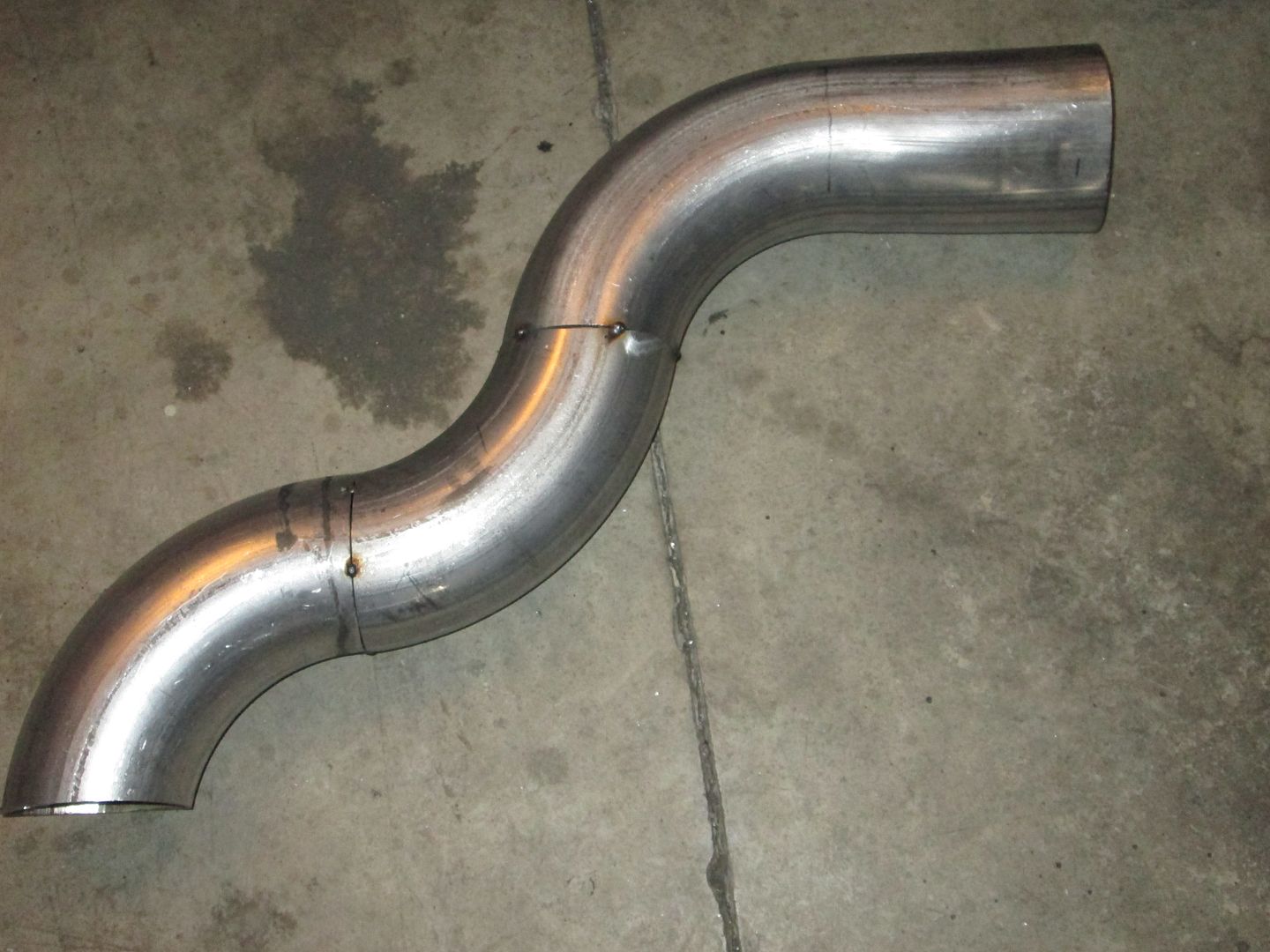
Then lots of cutting/test fitting the three different 90 degree bends to make this:
The shifter is hooked up and smoothly shifts to all gears:
Then I pulled the console/skeleton out so I could swap out the throttle cable to an 88 4cyl one that is longer. Then I started to mock up the cable and noticed that
the cable cam that was welded onto the throttle body wasn't properly centered and wasn't working with the available travel. Here is what it looked like before I modified it:
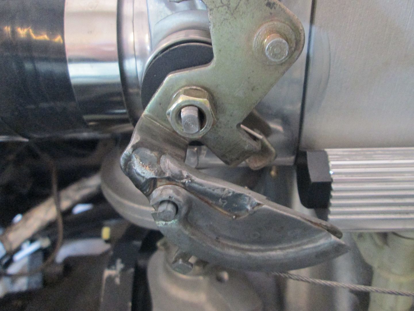
Then I cut it off, repositioned it and welded it back together:
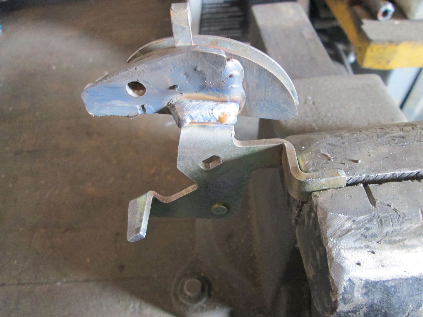
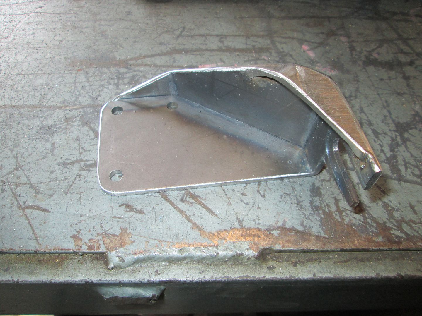
Here is a mockup with the cable and just starting to cut the material for the bracket. I will likely trim off the extra barrel end:
|
|
|
|
fieroguru
|
OCT 27, 02:35 PM
|
|
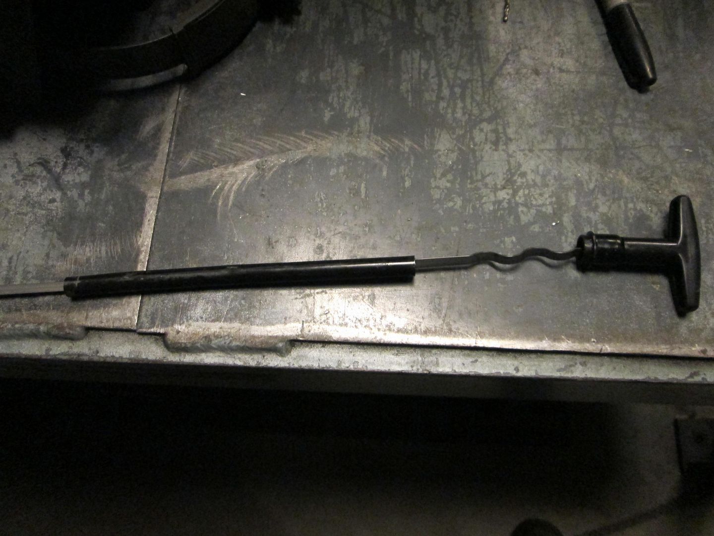
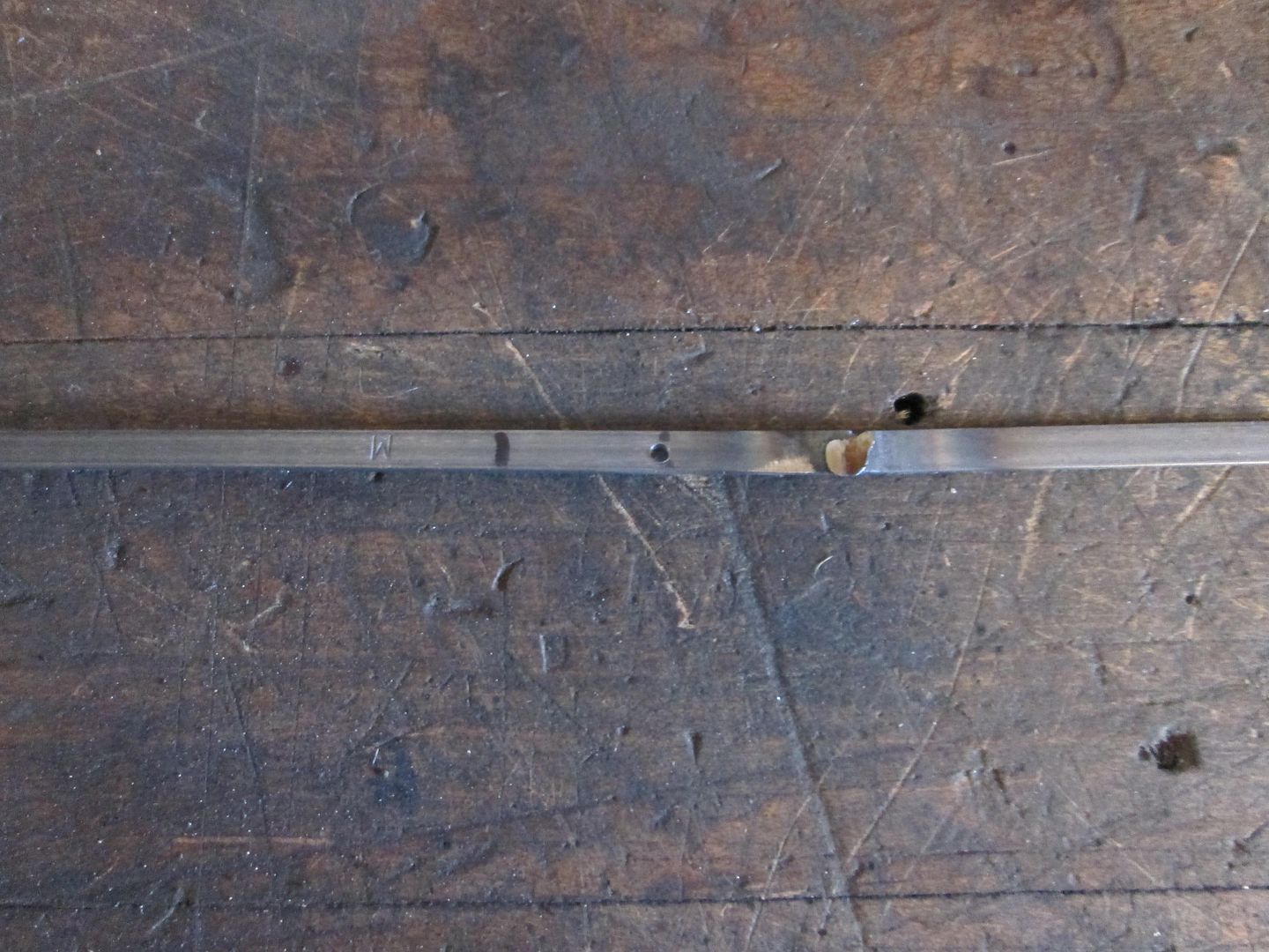
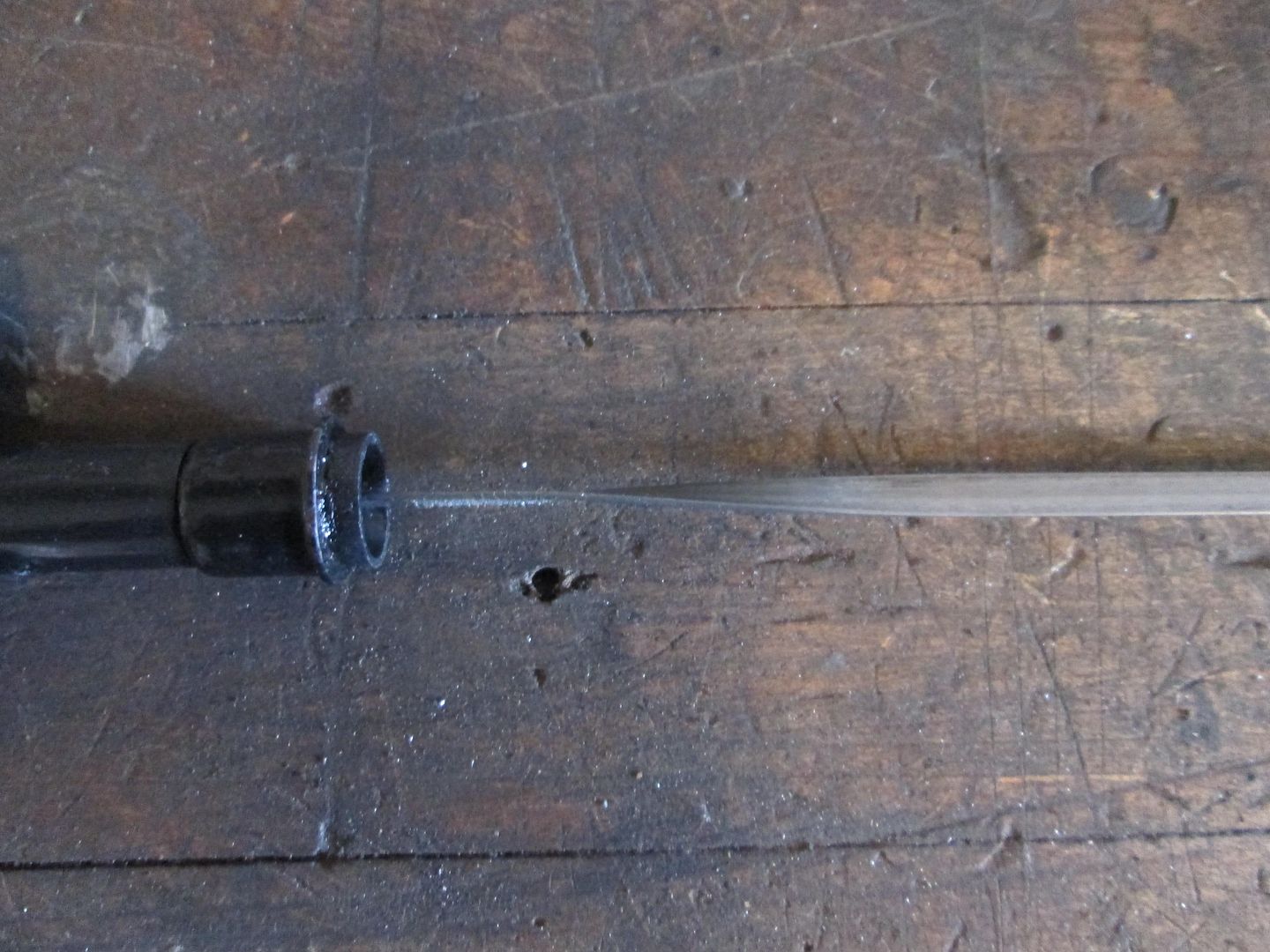
Finished the dipstick mod.
Pushed out the roll pin to remove the metal band:
using the section of the tube that was removed, mark the new hole location, drill hole, mark the new cut line, and place a tack weld where the seal retainer ring goes.
Install seal retainer ring:
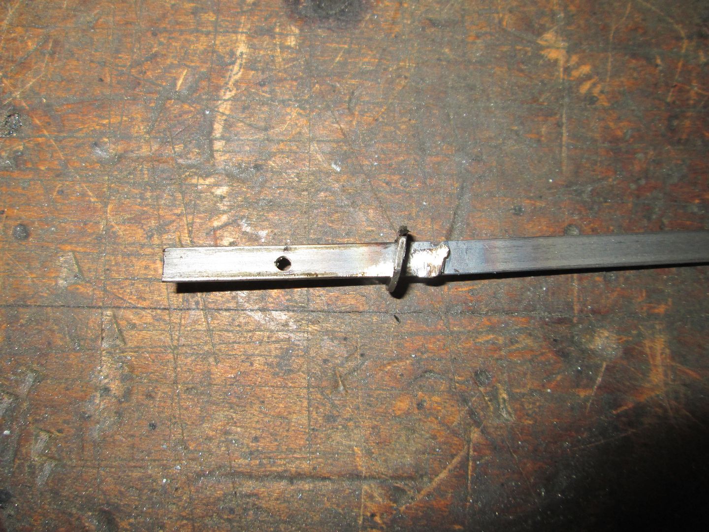
Install seal sleeve, handle and press in the dowel pin. In this pic you can also see the section of the tube and section of the banding that was removed::
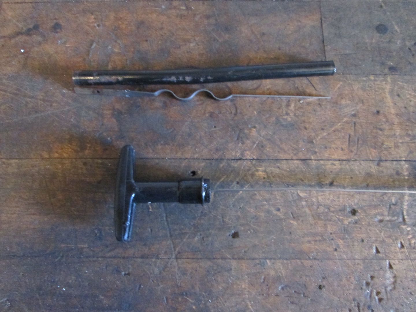
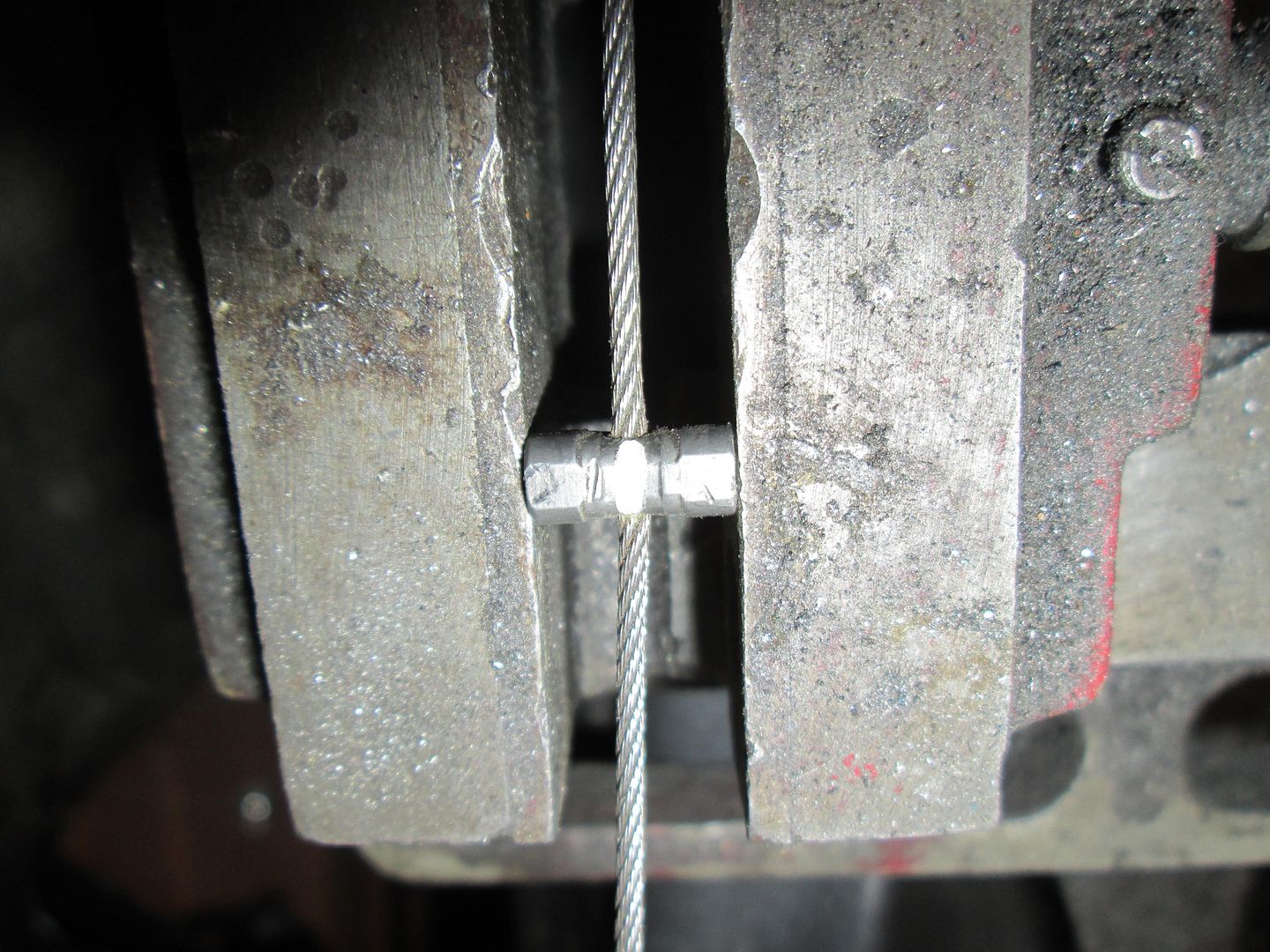
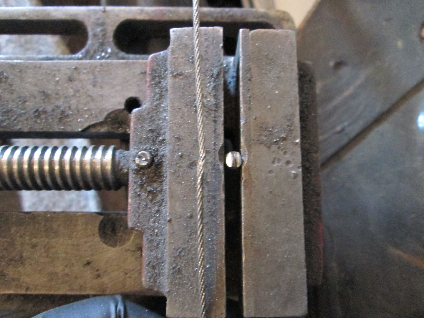
When I did a test fit in the car, the handle was perpendicular to the valve covers. Not really any issue, but I wanted it parallel, so I put the banding in the vice and used a crescent wrench to twist the banding 90 degrees:
Welded up the shifter bracket and smoothed the welds:
Welded up the cold air intake (still need to add the MAF mount):
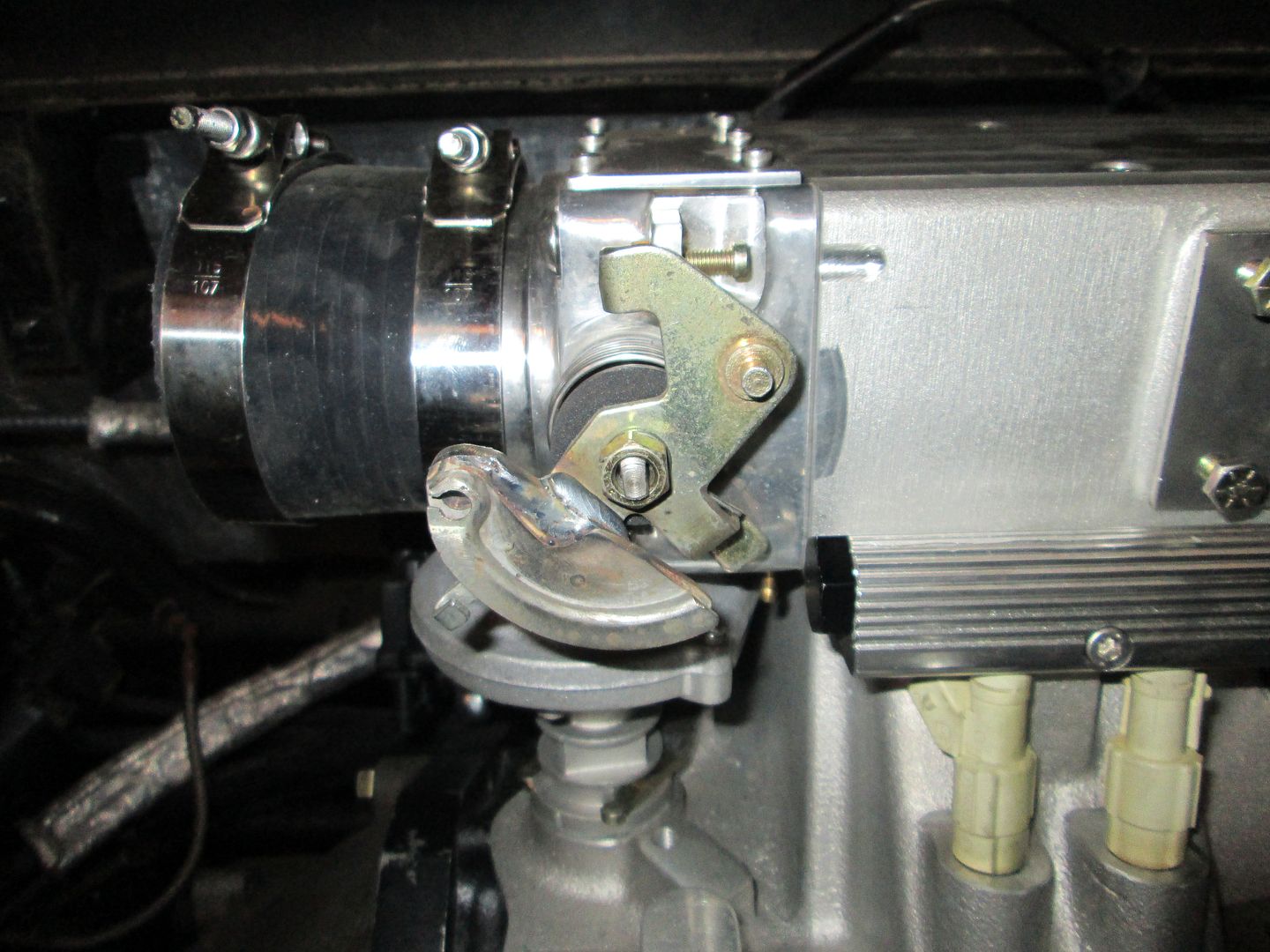
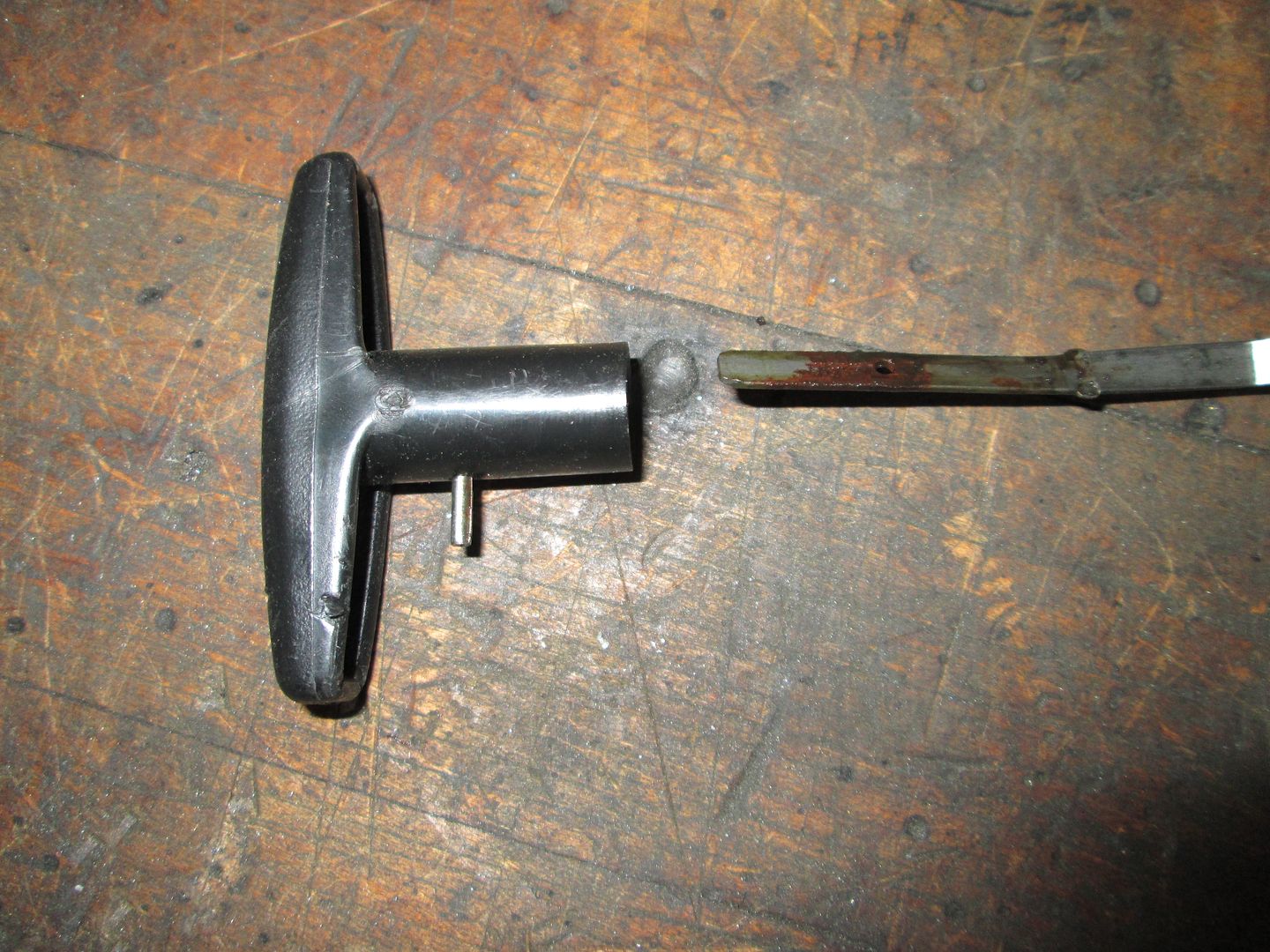
Removed the extra barrel on the throttle cable. I used my portable drill vice to hold the barrel, then carefully used a cut off disk to slit the barrel most of the way to the wire (but making sure not to nick the wire). I did this on both sides, then snapped it into 2 halves.
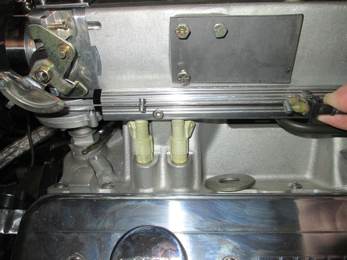
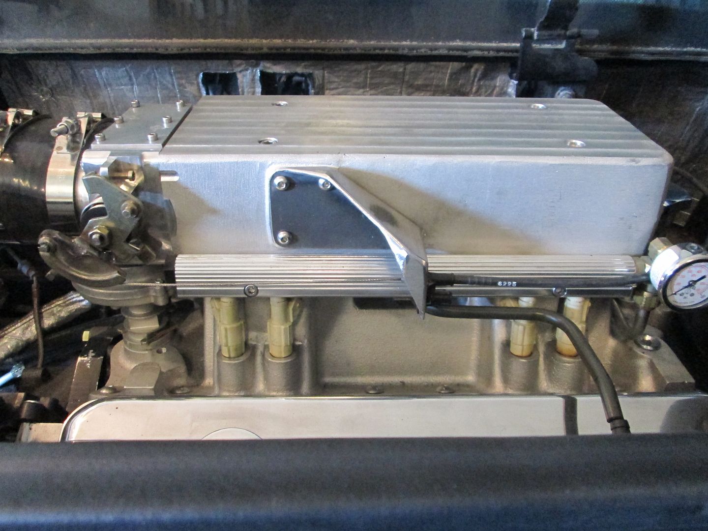
Finished up the throttle cable bracket, welded it and smoothed the welds. It used the factory style mounting and retainment for the 88 throttle cable:
 [This message has been edited by fieroguru (edited 10-27-2013).]
|
|
|
|
fieroguru
|
NOV 10, 06:18 PM
|
|
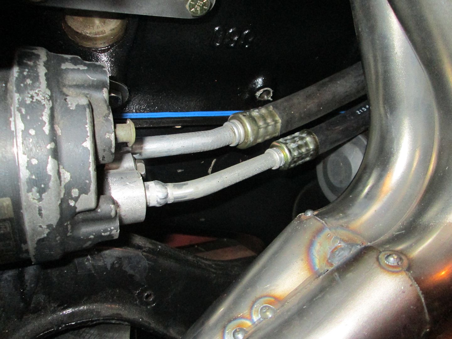
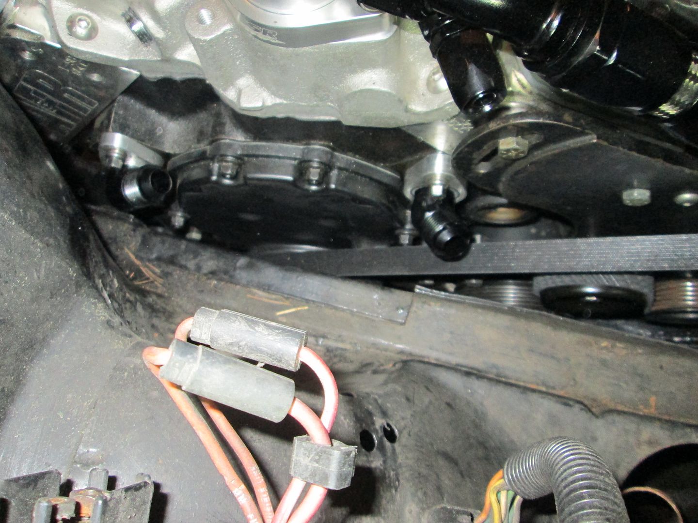
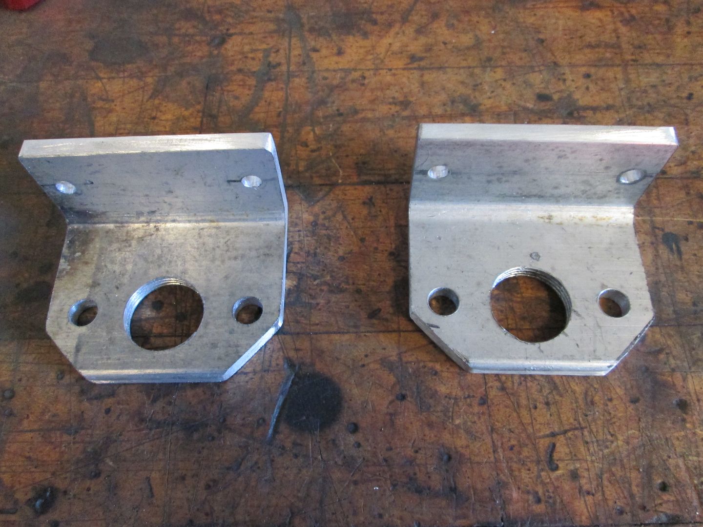
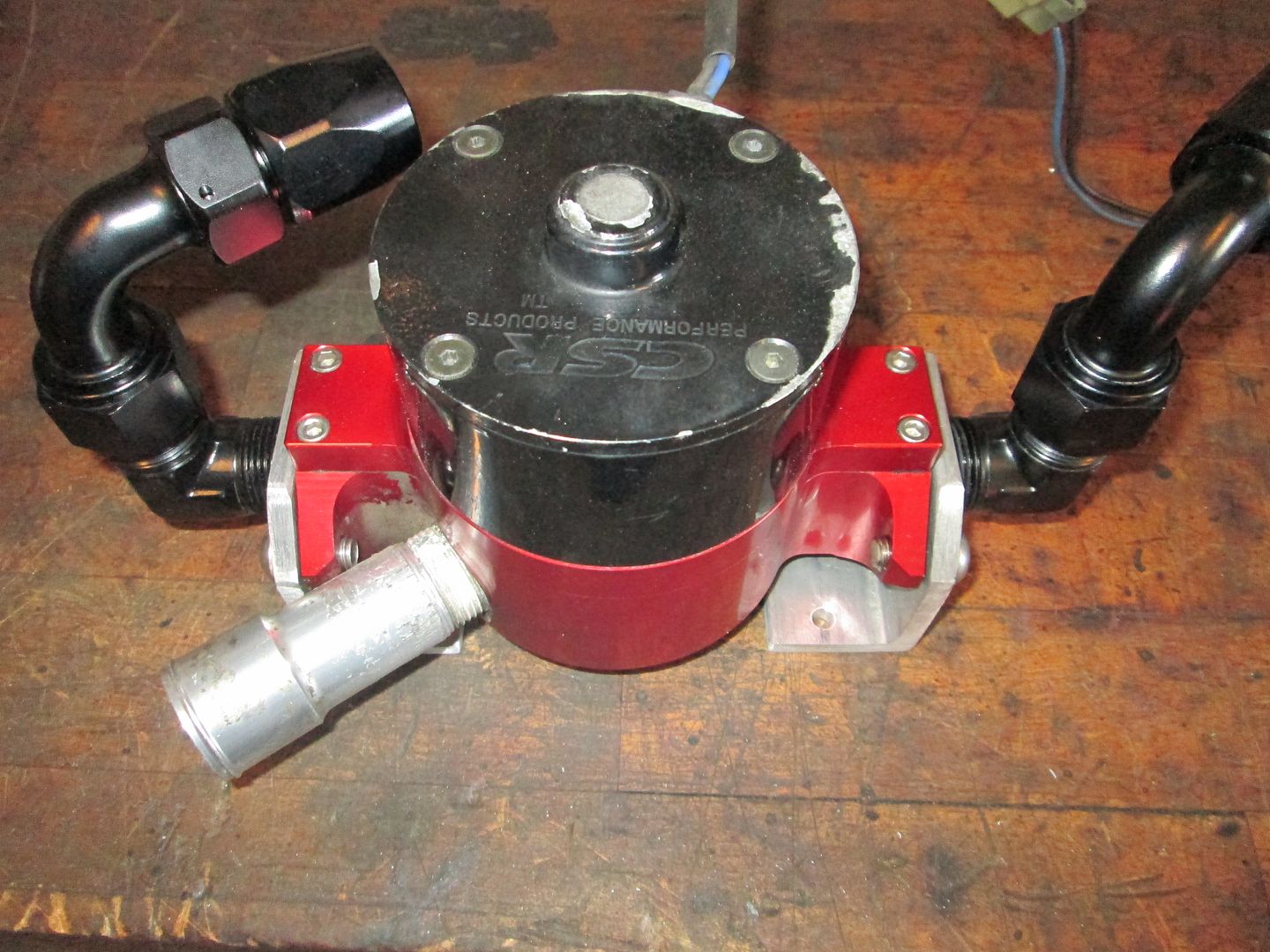
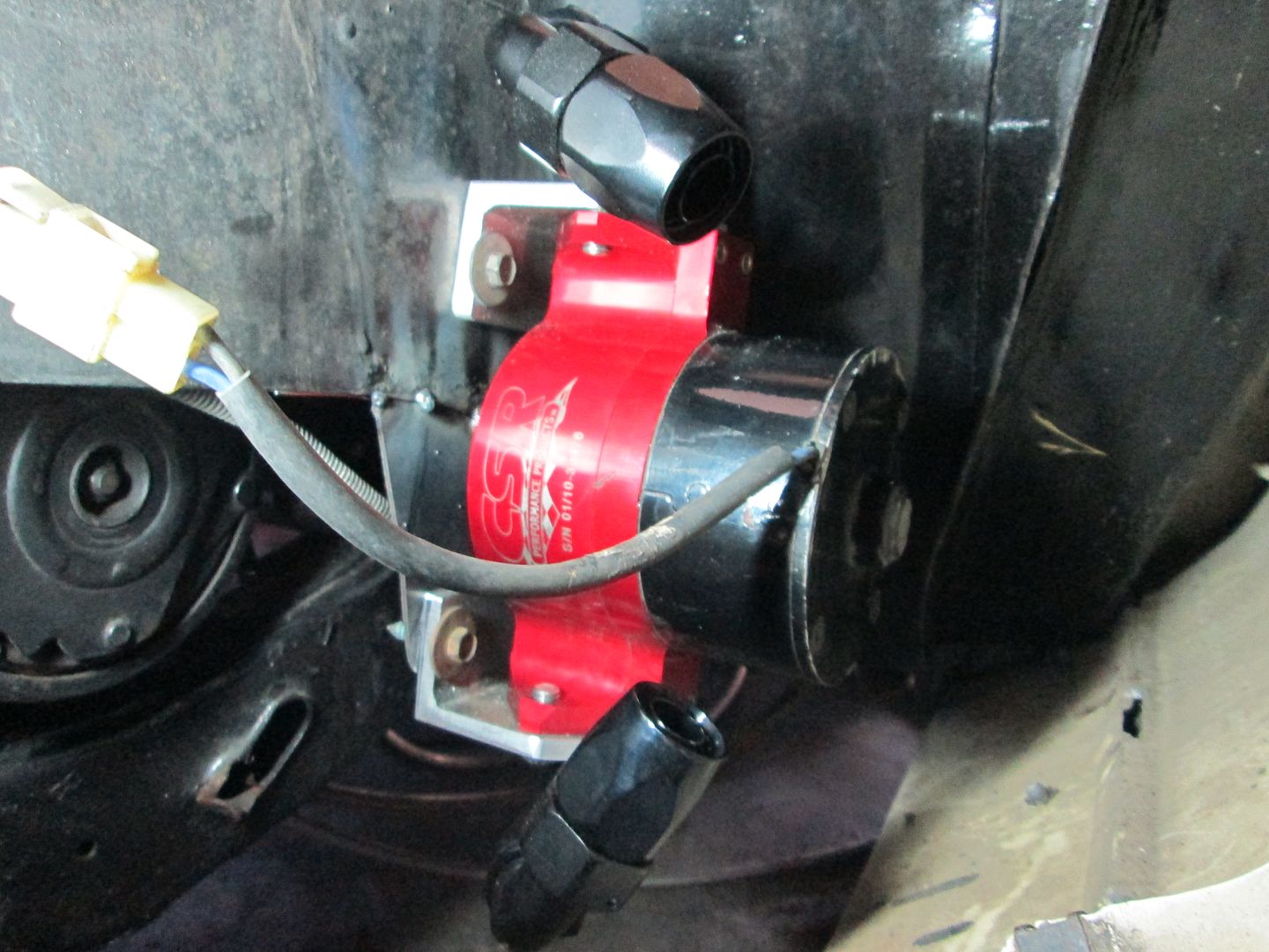
Been out of town for the last week or so, but finally got back to working on this car. Before I left, I had started making these aluminum angle plates so the water pump would have mounting brackets, and I tapped the aluminum for the A/N fittings:
Here is the approximate location for the water pump. It is well below the water level in the radiator, so it should self prime when the radiator is filled.

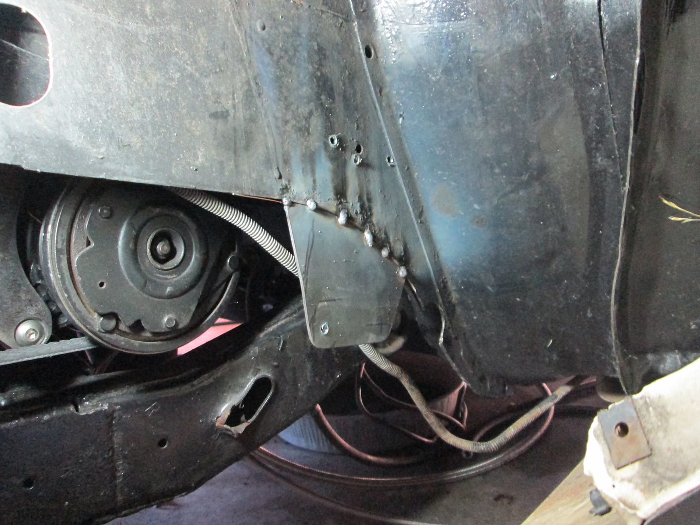
The bottom of the water pump wasn't supported, so I fabbed up a piece of sheet metal and tacked it into place. I will do more welding to it once the cradle is back out:
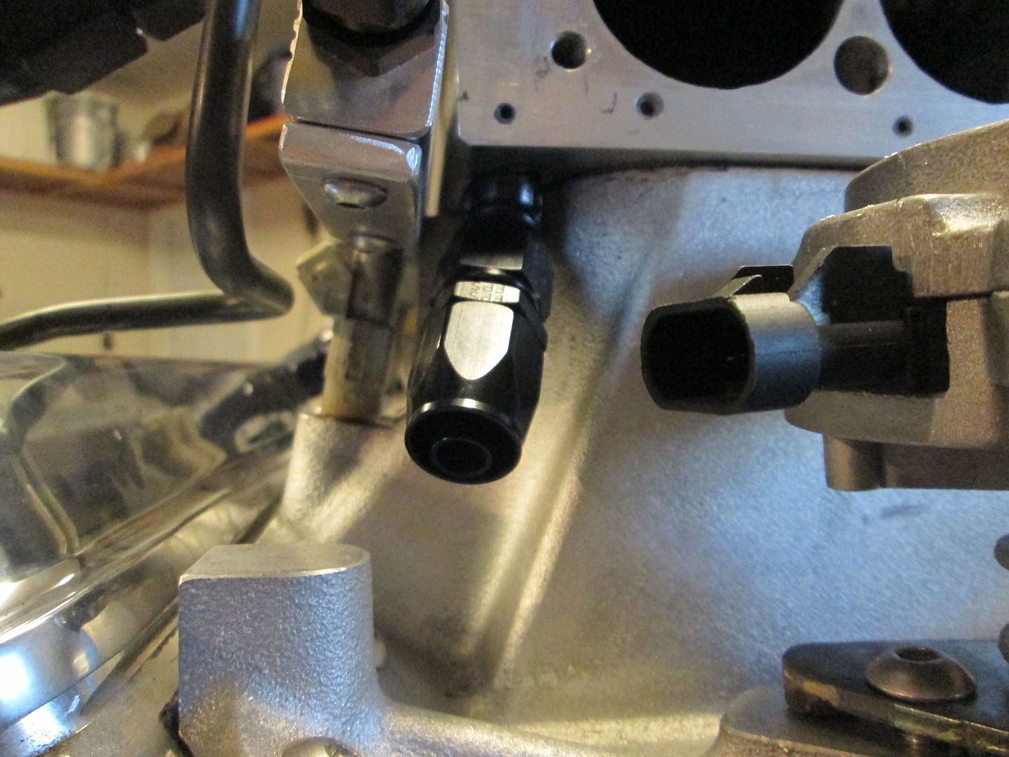
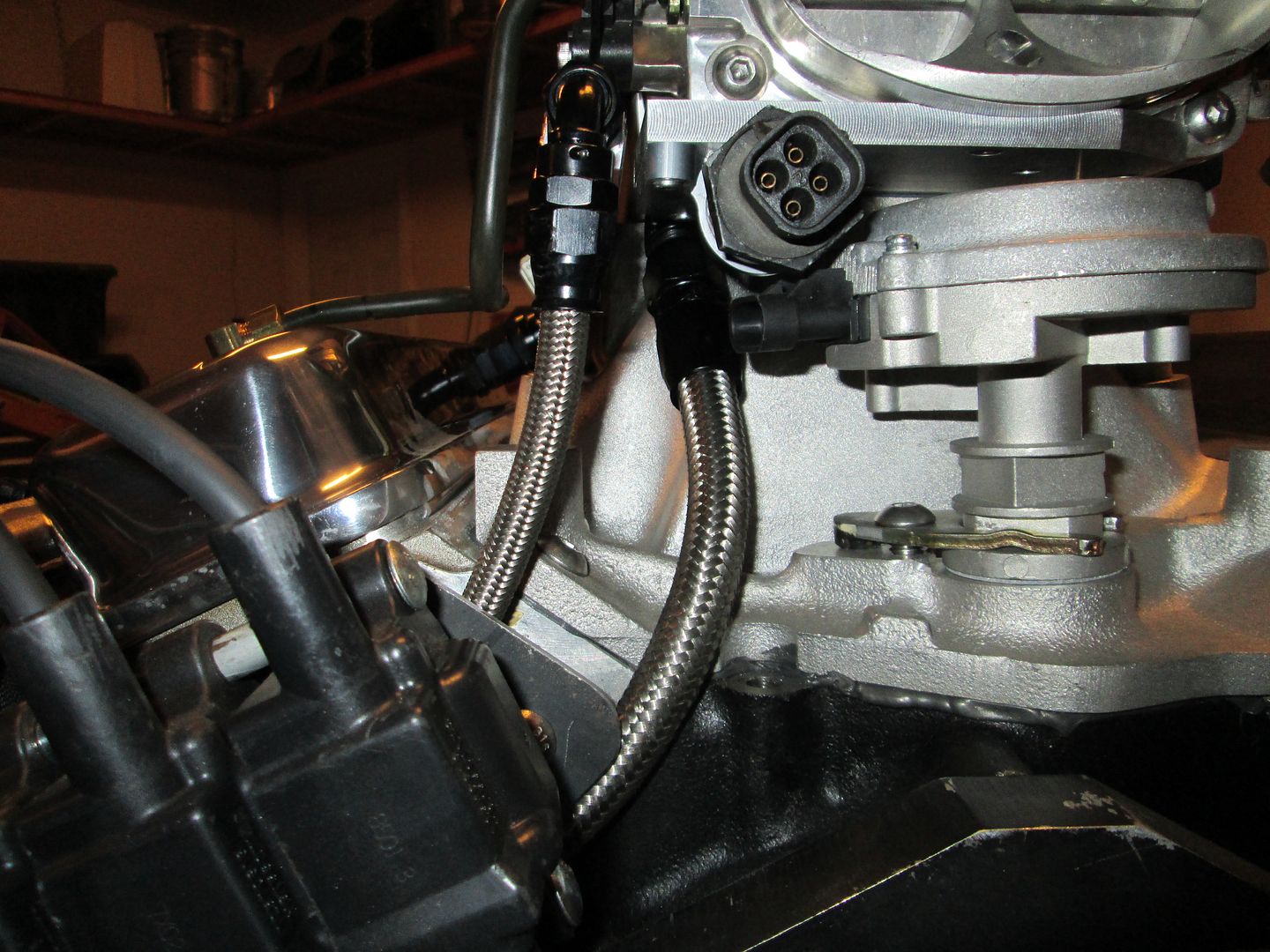
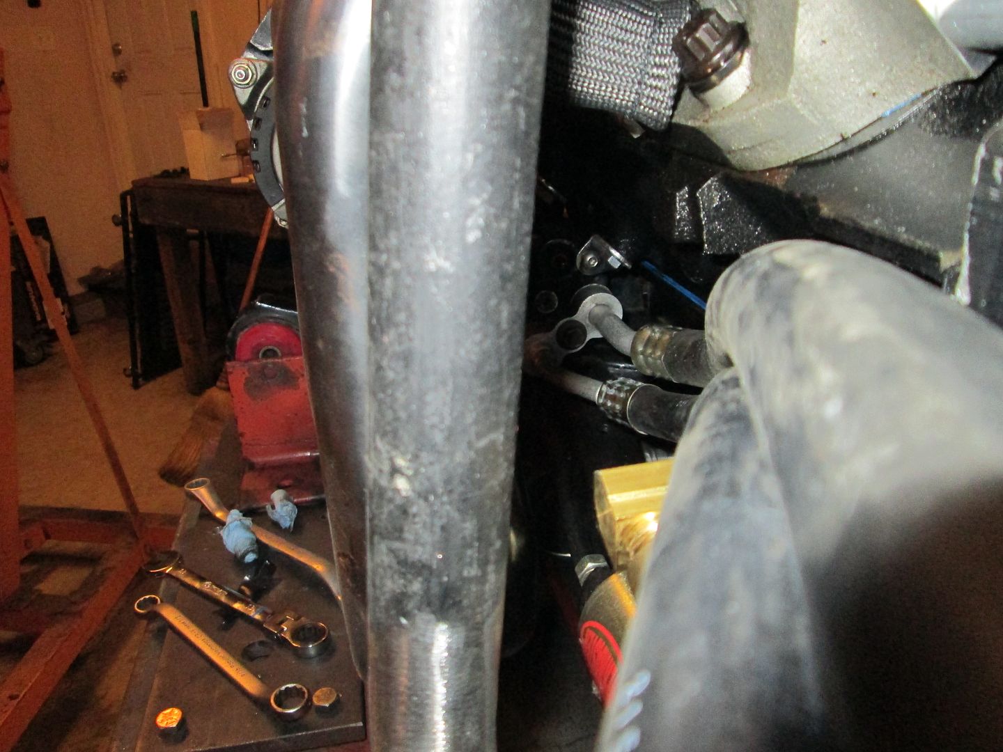
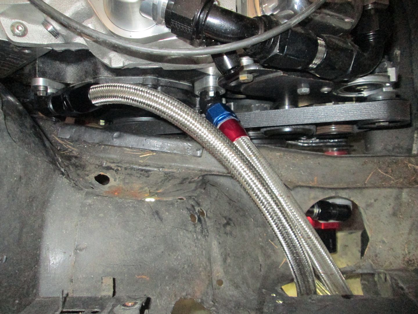
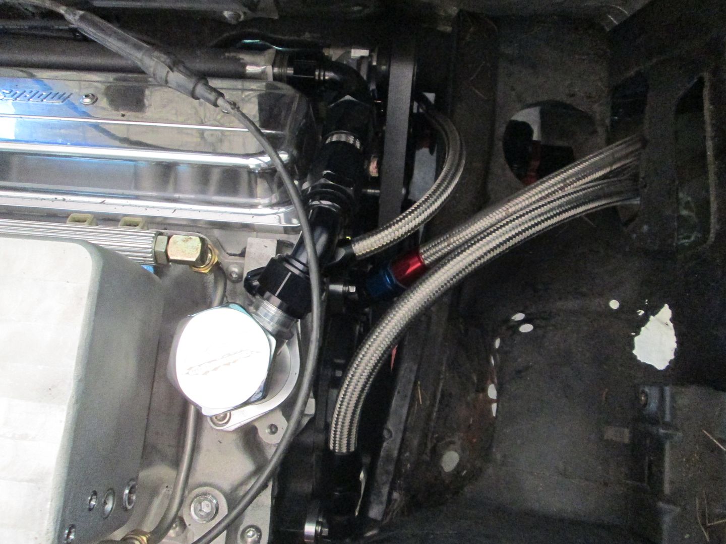
Then I started working on the braided stainless hoses. Here is one of the large hoses between the engine and water pump. The one with the red/blue fitting is just for mockup purposes (used), I had to order some more -12 hose for the other side:
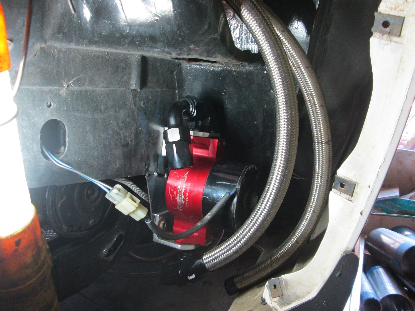
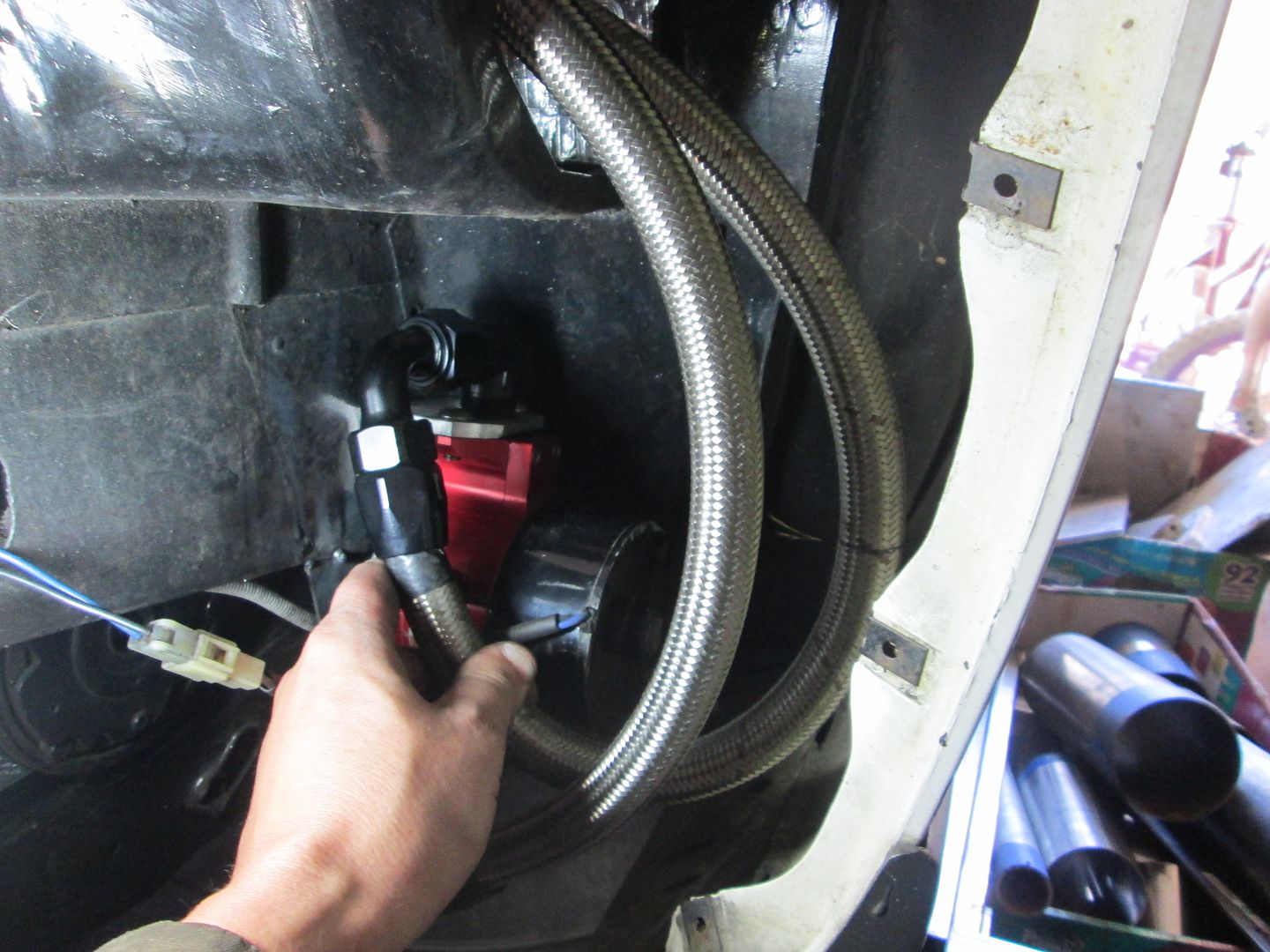
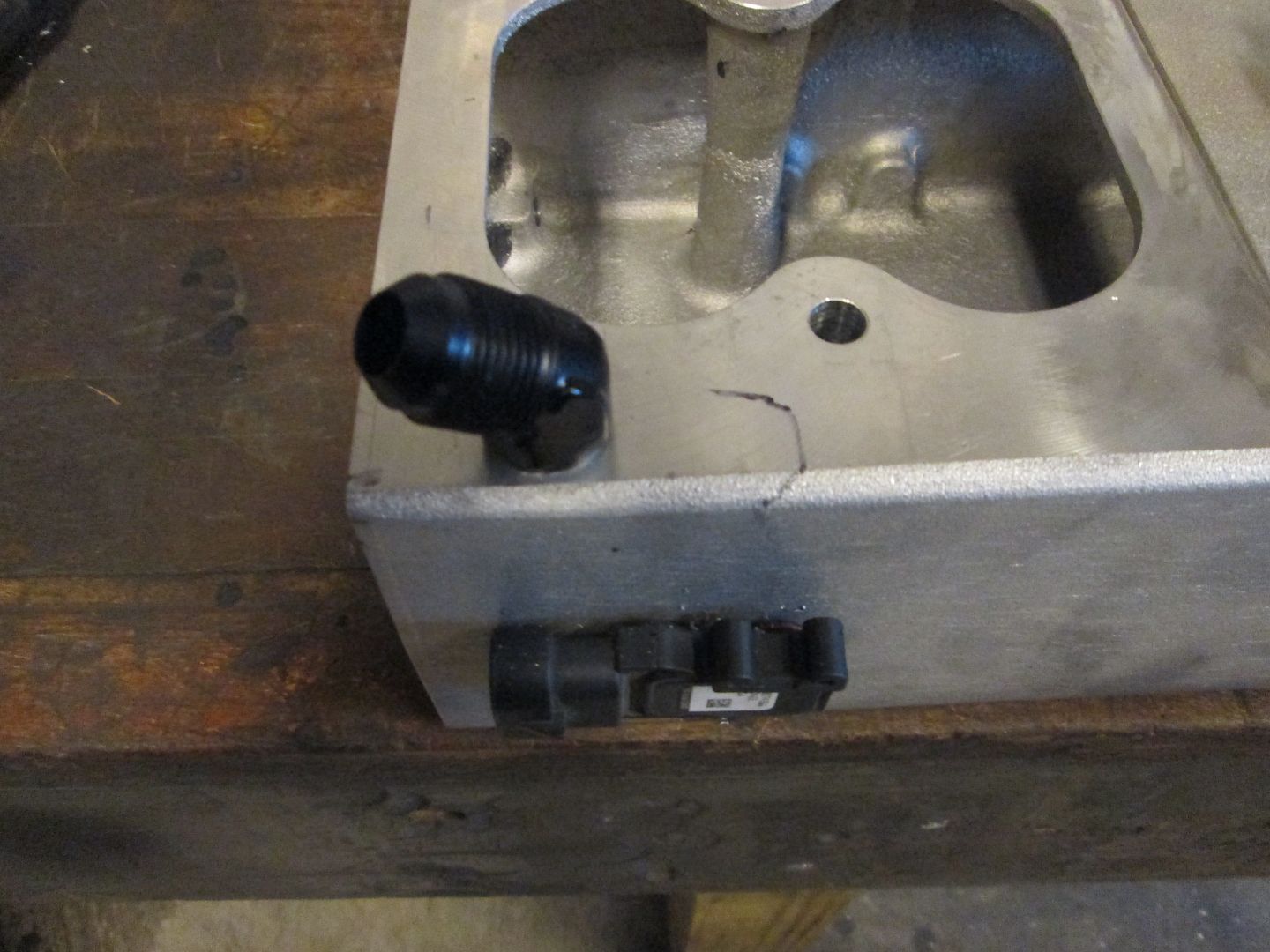
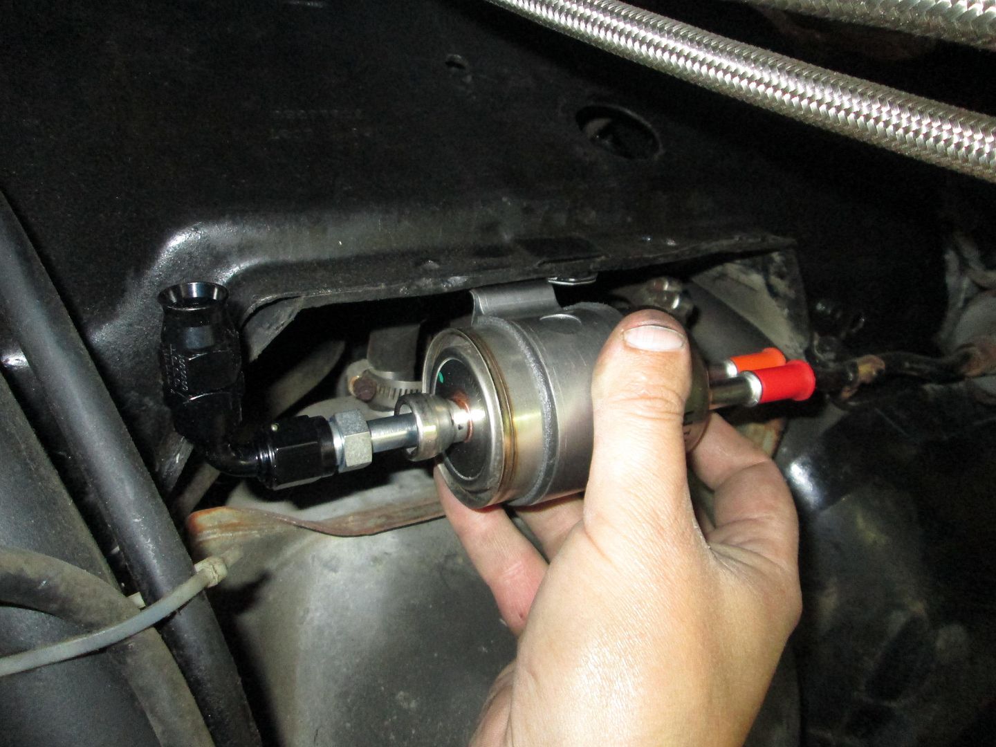
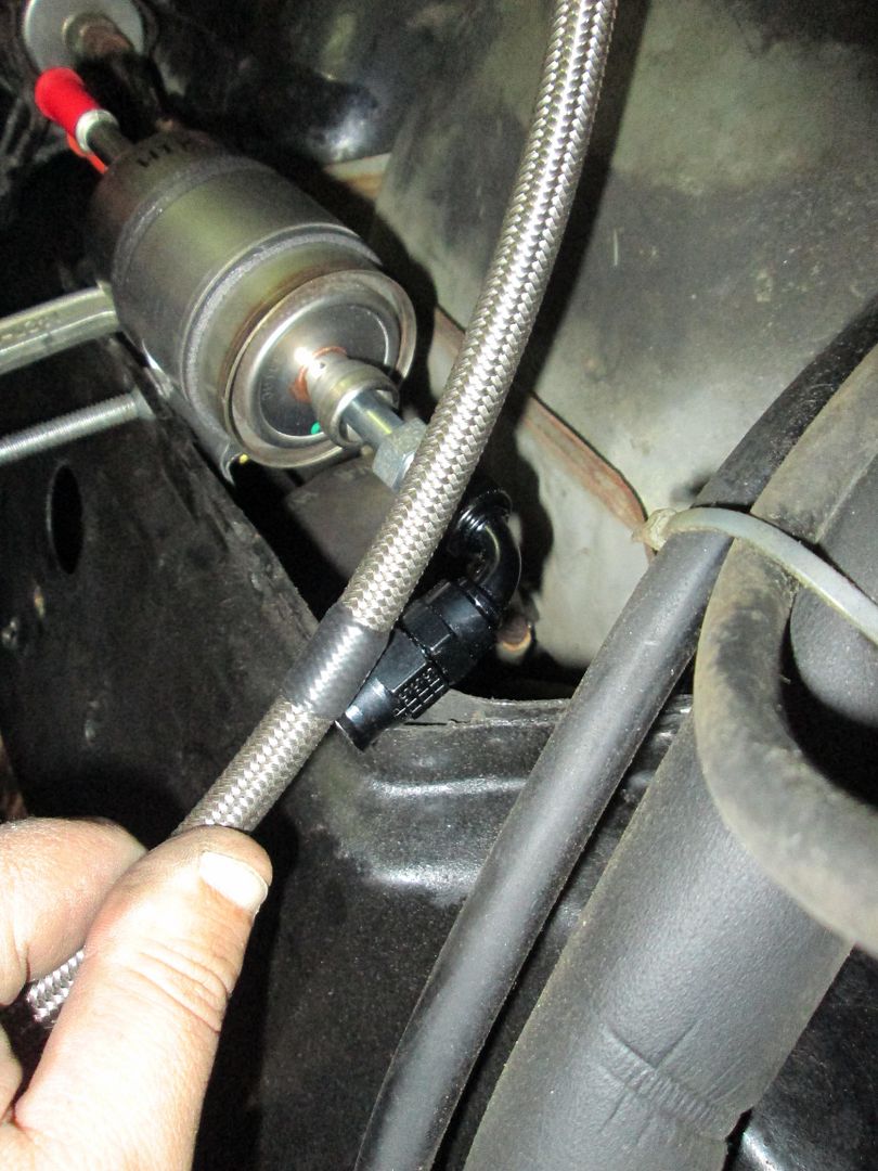
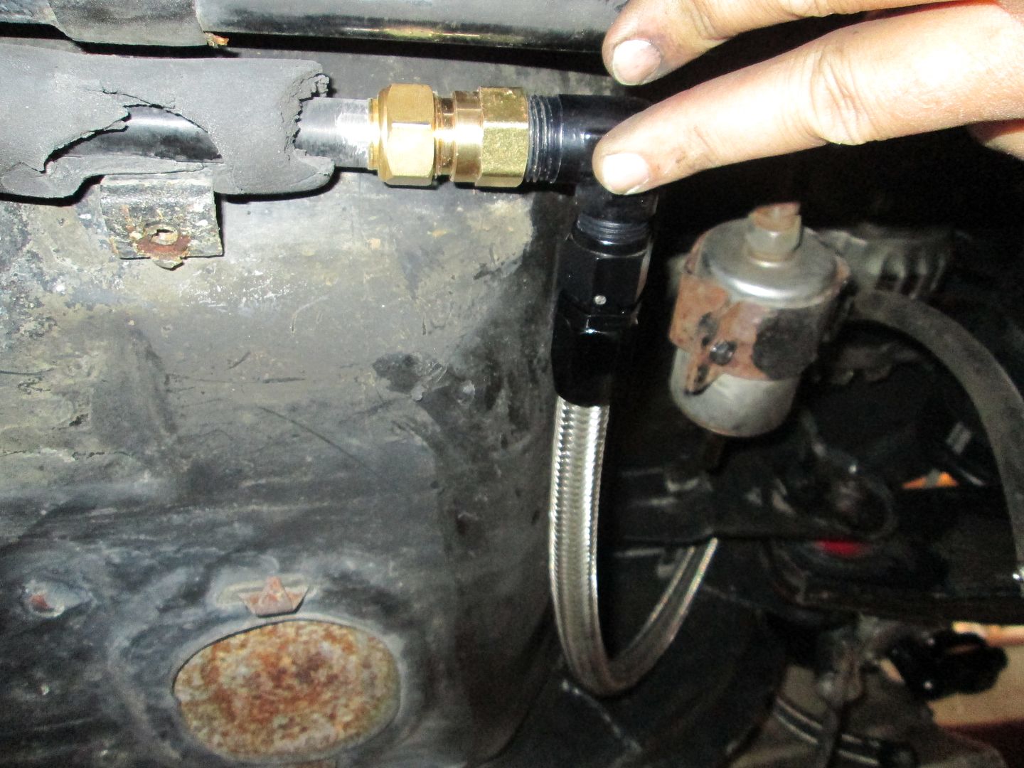
The new fuel filter/regulator will go in my normal spot, right behind the fuel tank.
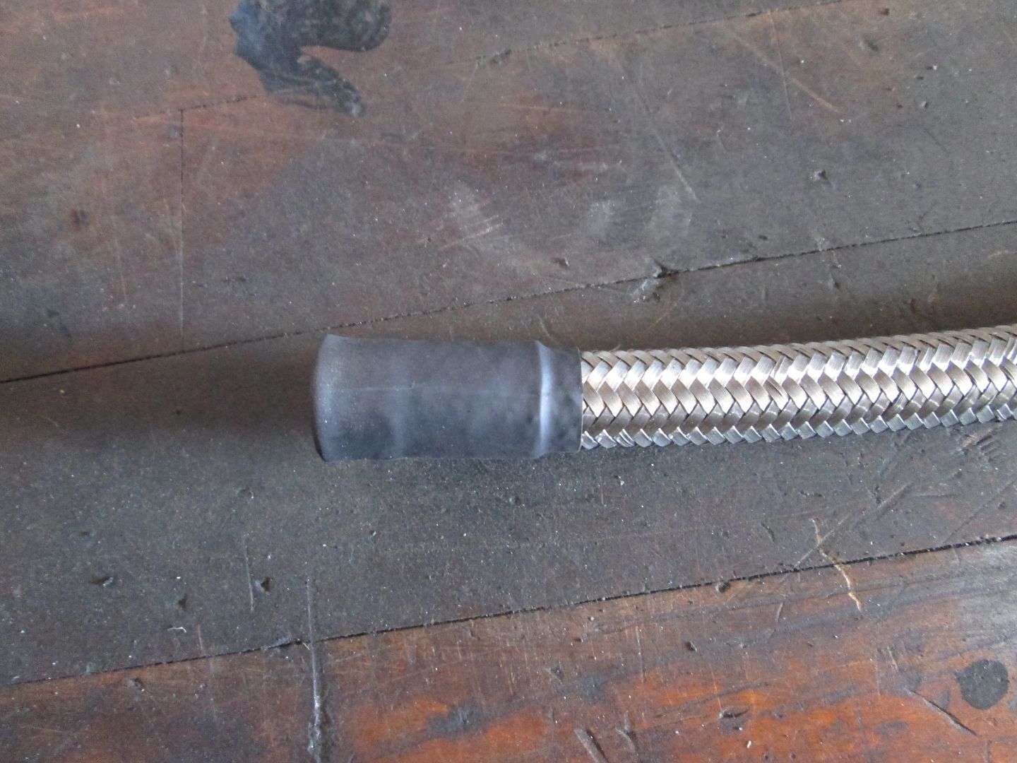
Measured the hose to length and then remove it to put on the hose end:
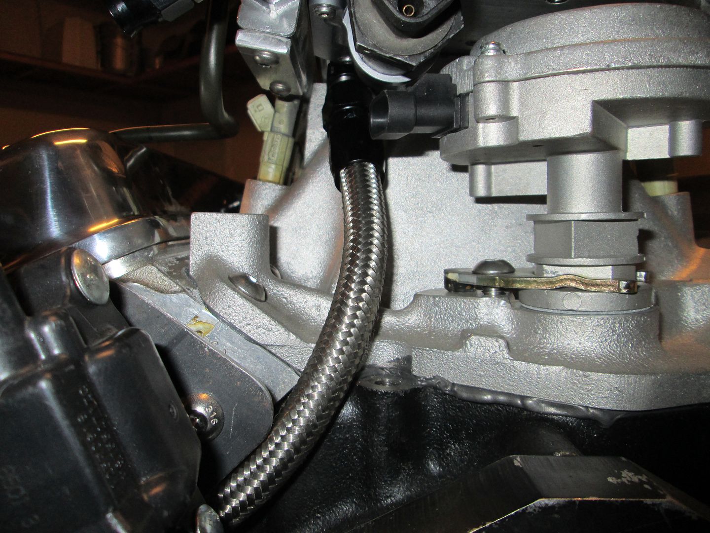
The brake booster hose was a little different. I had already installed the fitting on the intake side, but now needed to cut it to length and sleeve it so I can use a hose clamp to attach it to the brake booster hard line at the firewall. When I cut the hoses, I wrap the end tightly with electrical tape, then remove it to install the fitting. This time I removed most of it, but left about 2 wraps. Then I installed 2 sections of heat shrink and trimmed the hose again. Then installed the 3rd and last section of heat shrink and allowed it to overhang the end some to seal up all the stainless wires.
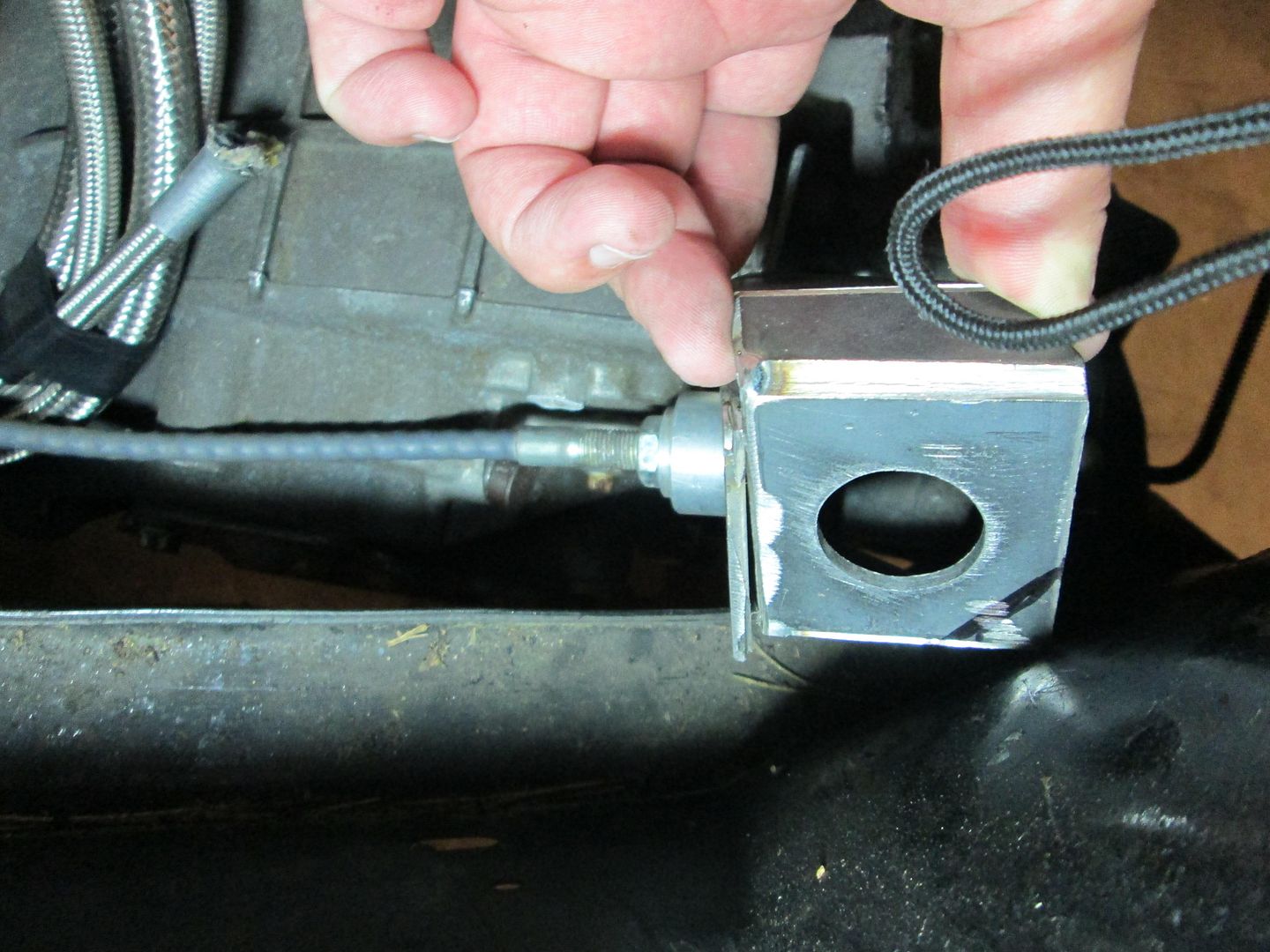
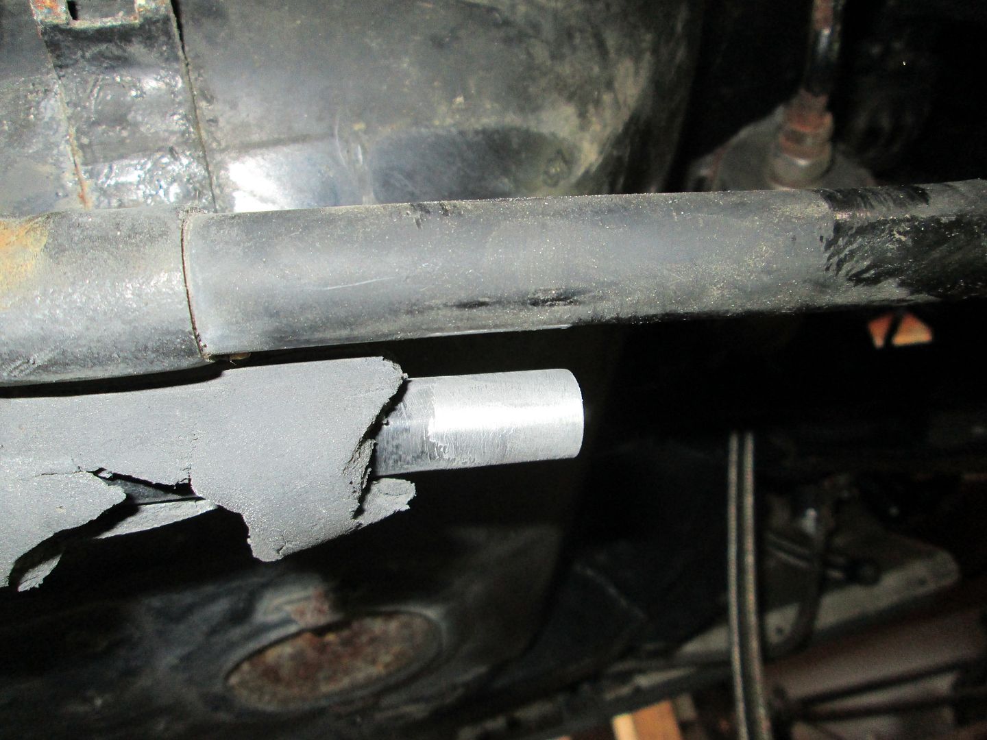
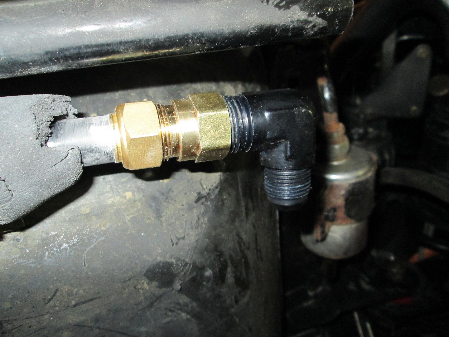
The heater hose supply hose was a little more involved. I trimmed the hard line, sanded it to bare aluminum, installed a 5/8" compression fitting, then a 90 degree AN fitting:
Braided Stainless hose central (ignore the red/blue mockup hose - it will be just like the others when done):
The other line (heater core return) will be routed into the passenger coolant tube (like the 88's) before the water pump, so it won't need to be routed into the engine bay.
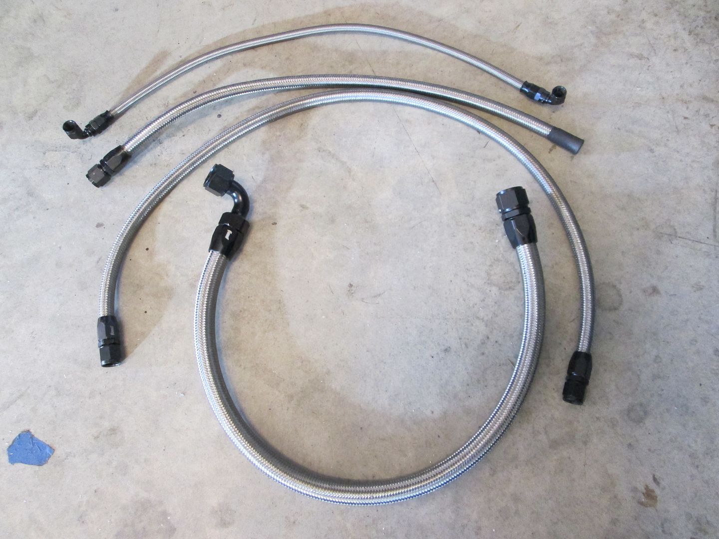
Here are the hoses I built today:
|
|
|
|
sleevePAPA
|
NOV 10, 08:25 PM
|
|
|
I've been waiting for an update on this. Nice!
|
|
|
|