LS4 / F40 swap - fieroguru (Page 22/216)
fieroguru APR 11, 07:38 PM
My first thread deemed worthy enough for the construction zone!!!!

My blue 88 clone has been running 88 front springs in the rear since 2009 and a member asked me to make him a set up the upper spring hats. I did a poor job documenting them when I made the original set, so here are some build pics:


And the assembly process:


Notice the black strut bushing has been flipped over to gain an additional 1" of travel in compression (for lowered cars)

The original upper spring hat keeps the new one in position:


Now why would you want to do this... It is a cheap way to lower the 88's and get an approximate 35% increase in spring rate. Just use the 84-87 front springs up front (remove 1 1/2 to 2 1/4 coils... depending on how low you want it), then take your front 88 springs, cut 1 coil off and install them in the rear with this new upper spring hat. The end result is a stance very similar to this one (24.6" diameter tires):

[This message has been edited by fieroguru (edited 04-11-2011).]

blackrams APR 11, 08:52 PM

quote
Originally posted by Bloozberry:

Wouldn't it have been easier to weld smaller brackets to your rear cradle cross-member and suspend the muffler with springs like the OEM Fiero?


quote
Originally posted by fieroguru:


What is this "easier" word you are referring to... not sure I know what that means.


Blooz,
You'd have to know Paul to fully understand but, I can assure you, whatever he does may not be the easy path but, it will hold together. Yeah, he's a bit nutty also.

------------------
Ron

Bloozberry APR 11, 09:21 PM
Ha! (I refuse to use LOL). I've seen the weird things he does to perfectly serviceable water pumps, Blackrams... I know he's nutty.

By the way Guru, welcome to your new home in the Contruction Zone! This thread is certainly worth it (Of course that means that all the rest of us are going to have to work a little harder to stay on page 1 given the daily updates you keep pumping out).
fieroguru APR 16, 11:47 AM
The exhaust is all welded up now. Just need to add the O2 bung and the stainless heat shield for the muffler/trunk area.


Then I played with the flywheel to confirm it fits the engine and the clutch combo will clear the transmission:


Test fit of old clutch:


In the transmission. I was able to spin the engine over about 10 times by hand w/o any rubbing/scraping:


I had plug an o-ring on the input shaft to see how deep the clutch hub rests on the shaft... about 1":


So on Monday I will call up SPEC and order my clutch... it's about $600.

[This message has been edited by fieroguru (edited 07-02-2016).]

fieroguru APR 16, 01:34 PM
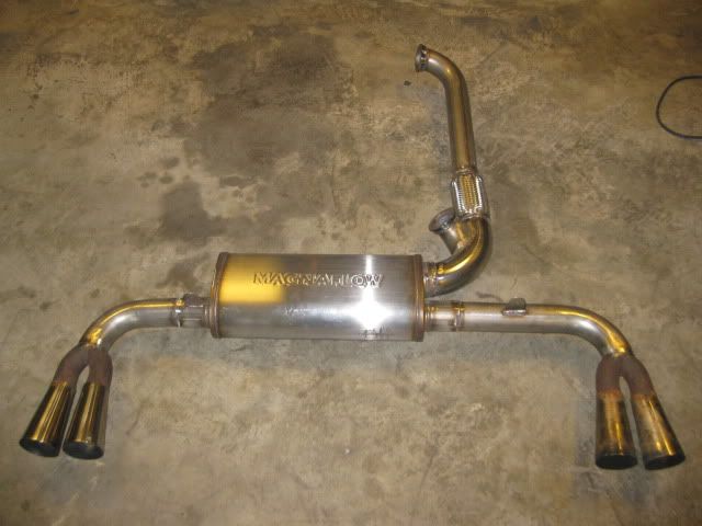
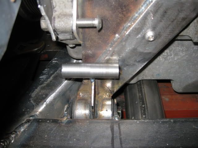
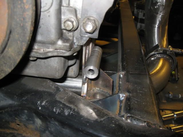
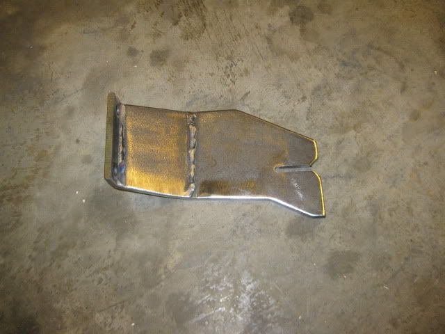
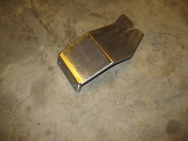
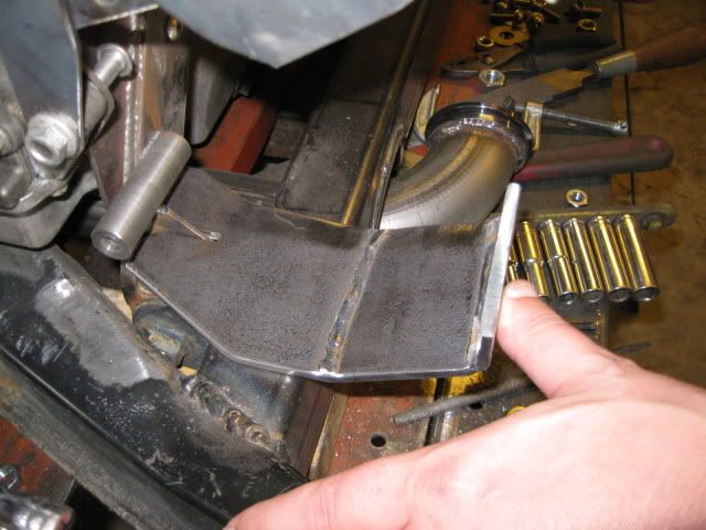
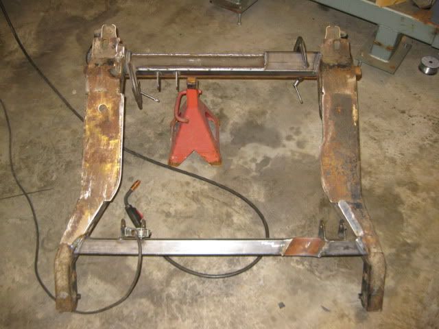
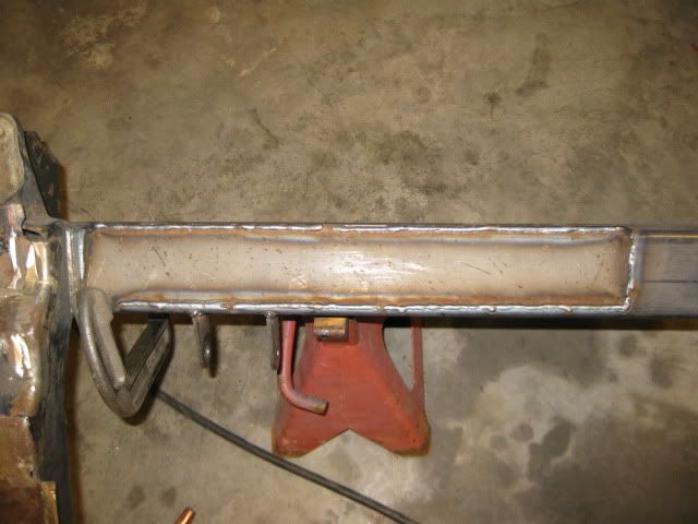
Boxed in the muffler notch in the cradle:

[This message has been edited by fieroguru (edited 04-16-2011).]

fieroguru APR 18, 07:54 PM
I ordered the 10mm plug wires, the coil terminals and the wire separators. So far the wire separators are the only parts that have come in:


Been thinking about the AC and Alternator mounting for quite some time and think I have it figured out. First order of business was to mock up a relatively stiff upper support to hold the AC compressor in the right general location so I could finalize the bottom and backside mounting points. Also used my angle pulley alignment tool to ensure the AC compressor was at the proper depth:


I picked up some metric nuts, then tuned one down to fit inside a tube (a section of an 88 trailing link tube), welded it in place and then turned the weld down smooth. I had to mill a flat on the back side to clear the thicker portion of the front engine bracket. This tube will act as the lower AC compressor mount. It is just tack welded to the front engine bracket, but it will be fully welded:


For the rear mount, I am planning to weld a nut into a 1x1 square tube and then cut its legs to fit up against the thick portion of the front engine mount:


The front engine mount will also have a lower strap that will go under the AC compressor and support the bottom side of the LS4 alternator. Then I will go back and remake the upper bracket that goes above the AC compressor and it will connect to the top set of bolts on the Alternator.

[This message has been edited by fieroguru (edited 04-18-2011).]

fieroguru APR 23, 06:32 PM
The plug wires and coil terminals showed up last week, and I ordered the Spec Stage 4+ clutch on Wednesday...

The rear A/C support boss is tacked into place and that restores the AC compressor to 3 points of attachment just like stock:


I decided to stick with the LS4 alternator and incorporate the top portion of the bracket with the 1/8" plate that supports the AC bracket. So I bent some more 1/8" material, bent it a couple of times to provide some stiffness and clear the engine block, then tack it to the upper AC bracket:


The nuts for mounting the Alternator will be welded to the back side of the bracket and a small gusset will be added to the belt side to close off the nut area. The bottom bracket will be similar and come from under the AC compressor to attach to the alternator.

Since, the alternator could now hold itself into position, the water pump and the last idler (just held in place with a magnetic base) were installed to show the final belt routing. I will find a smaller diameter idler for the one between the Alternator and AC. The balancer, alternator and AC compressor all have quite a bit of wrap, so there should not be any issue with belt slippage.

[This message has been edited by fieroguru (edited 04-23-2011).]

fieroguru APR 26, 05:15 PM
The clutch arrived today! The list price was $639, but I was able to get it for $575 shipped through LMPerformance.com. This is the 2nd most expensive part for this swap ($749 for the Camshaft kit was #1) excluding the original purchase price the engine...


The clutch disk measures at 9 13/16" at the friction material (listed as a 10" clutch) and is one of the largest diameter clutches you can get for this application w/o mixing/matching disks and pressure plates or getting into some trick self adjusting pressure plates.

It weighs in at 16.52 lbs on the wife's 30 lb postal scales, so the combined flywheel/clutch/pressure plate will be 27.7lbs... which is about 15 lbs lighter (and the flywheel about 1" smaller diameter) than my old SBC flywheel/clutch/pressure plate setup or about 35% lighter... that should help free up some more whp!

The other bit of good news is I might have my 4T65E-HD sold for $650 and that should offset the hit to the wallet from the clutch.

[This message has been edited by fieroguru (edited 04-26-2011).]

dobey APR 26, 06:16 PM
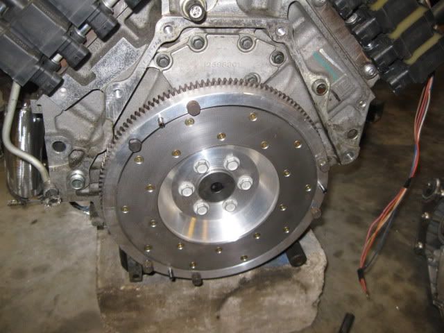
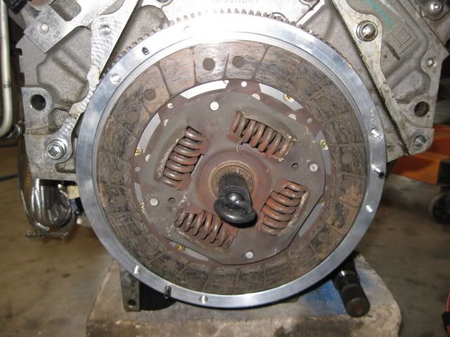
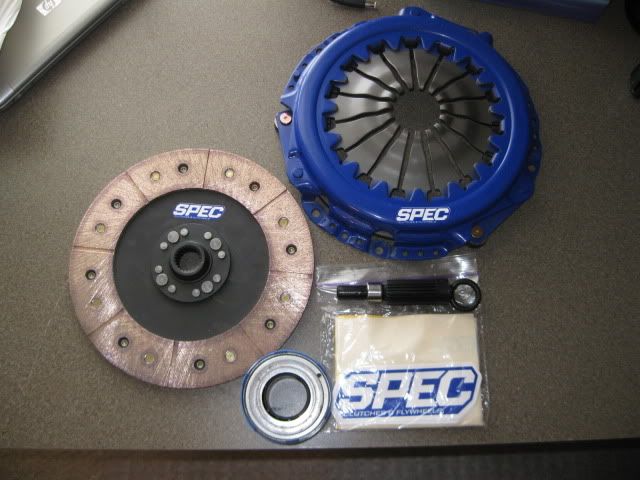
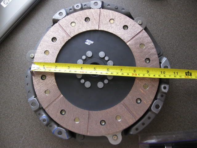
Nice. I still need to figure out a flywheel/clutch solution for mine.
fieroguru APR 26, 07:36 PM
More progress on the Alternator bracket. I still need to weld this lower plate into the front engine mount/AC bracket and notch the cradle directly under the bracket to allow 1/4" movement, but it is starting to take shape:


I found the sister to the more rounded pulley off the balancer and used it for the AC/Alternator idler. Then figured out where it needed to be for clearance all around and drilled the upper plate for the idler. Then a scrap belt was clamped together to show the final accessory drive. I will cut the belt at the clamp, measure the length and pickup a new belt:


Also, started messing around with intermediate shafts. Originally, I had planned to just use the custom tripods I made for the SBC/F40 swap, but the Passenger side tripod will not clear the side of the block (Y-block construction strikes again and the F40's axle location is closer to the block). So I will probably use the modified tripod/corsica axle on the driver side (short axle) and then use a stock G6/F40 Driver side axle on the passenger side with a longer custom intermediate shaft. I had picked up a couple of Saab 9-3 intermediate shafts and will cut them apart, machine a hollow sleeve to go inside, press them back together and weld them together at the seam and 4 plug welds on both sides of the main seam. The wall thickness of the intermediate shafts is about 4mm and the I.D is about 1.45"... so I will turn down some 1.5" tubing to make the inner sleeve.
Here are the two shafts with one already cut apart:

[This message has been edited by fieroguru (edited 04-26-2011).]