
 
     |
| Blooze Own: An F355 Six Speed N* Build Thread (Page 22/126) |

|
Bloozberry
|
OCT 03, 09:51 PM
|
|
Thanks for the suggestion Erik… I haven’t had this thing out in the sun yet. It’s bright enough to look at just in the darkness of the cave I call my workshop. (insert smiley face with shades)
So on with the water log/pump installation: The first thing to do is install the cam pulley. It’s fairly straight forward… just slip it on the end of the cam shaft with the snout pointing outward, and use any old 8mm X 1.25 bolt in the end of the shaft to draw it into place. When it’s seated correctly, the end of the shaft is flush with the end of the snout.
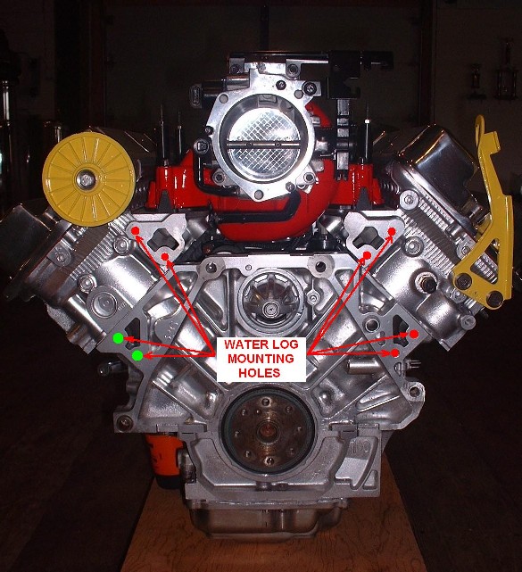
The next step involves having some RTV handy since some of the water log mounting bolts penetrate into the water jacket. I was curious to which ones needed the RTV and decided to shine a light into the four mounting holes on the engine block and the four in the cylinder heads to see. I was surprised to find that only two of them did, so I imagine GM specified RTV on all of the bolts to make things easy on the assembly line. The two that needed it on my block are the ones highlighted in green, the red ones were fine, but I applied RTV to all the bolt threads just in case:
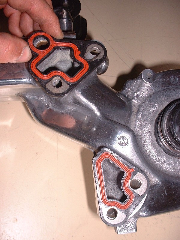
Apart from the boltholes, the way the water passages seal up against the block and heads is with a metal gasket that has a neoprene-like seal embedded on both sides. It’s a little tricky to get all four seals on the log and get it up to the block without the seals falling all off since nothing captures them. The trick is to slide all eight mounting bolts through the log and hang the seals on them.
Another complication is that you must hang the little water pump belt off the cam pulley and make sure as you raise the log up to the engine, that you slip the water pump pulley into the belt loop. If you don’t do this, you’ll soon find out that there isn’t enough room between the snout of the pump pulley and the block to install the belt. I know this first hand. Needless to say, lifting this contraption up to the block took two hands so there aren’t any pictures of it going into place. Here it is though, in the process of being torqued down. All eight get torqued to 18 lbft.
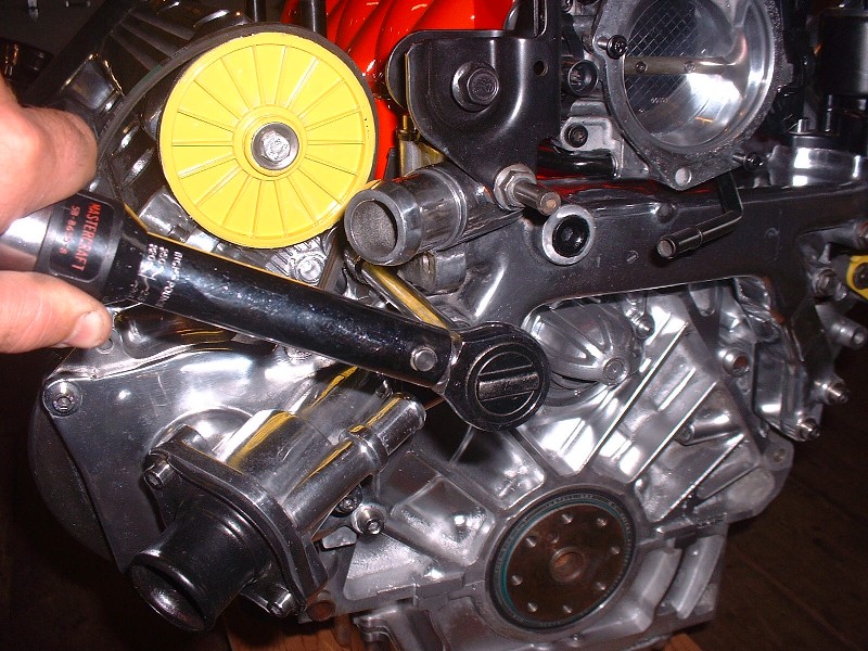
Next up is the little water pump belt tensioner. In this series of three photos, the first is mounting the tensioner to the log with two long, small diameter studs. (Notice the space between the tensioner pulley and the cam pulley at this point).
This photo shows how you "lever" the tensioner pulley against the force of the tensioner spring towards the cam pulley, by using a ¼” drive socket-wrench in the handy-dandy little ¼” square hole on the back side of the tensioner arm. Notice how much closer the tensioner pulley is to the cam pulley?
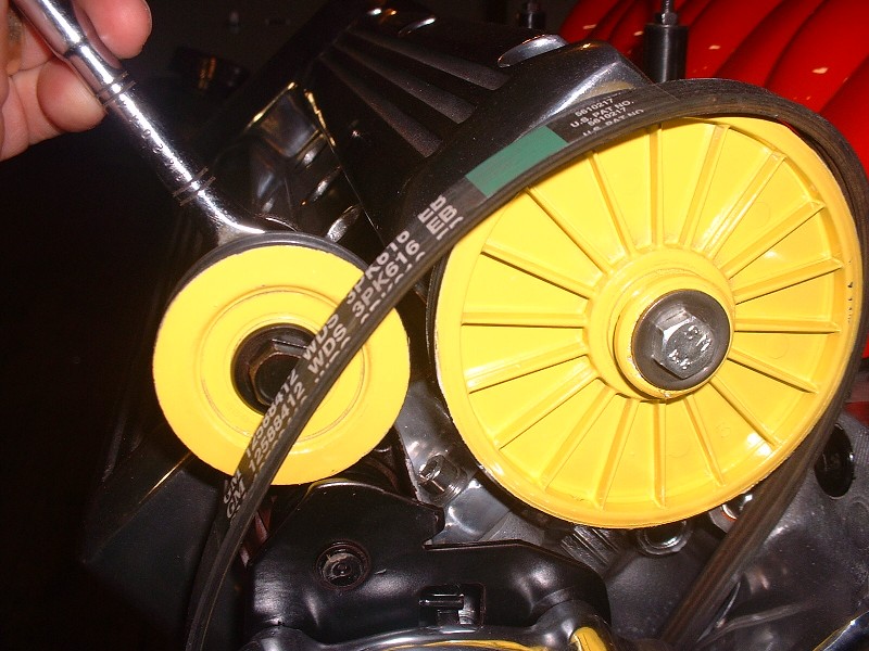
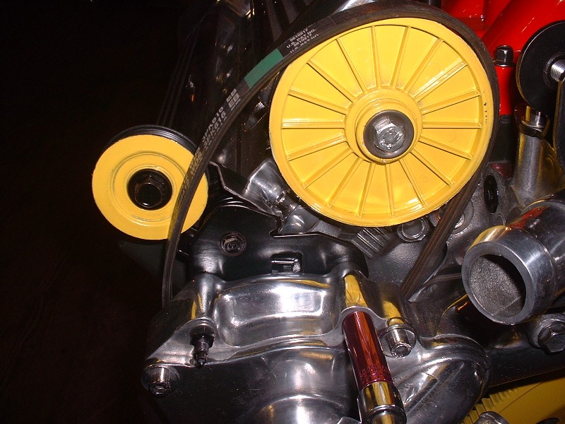
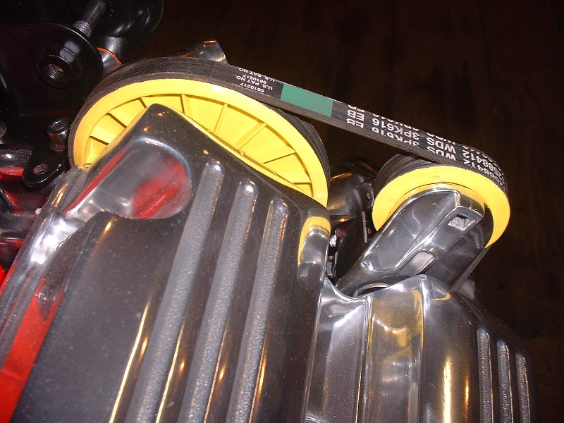
With the arm fully retracted there’s enough slack to slip the belt on the tensioner pulley, and from there it’s just a matter of releasing the pressure on the tensioner. It’s easy to get the belt on crooked as I found. I had to re-take this picture after coming back to the office, downloading the photos, and seeing that the belt wasn’t properly seated on the cam pulley. Good thing I noticed before trying to start this puppy up! This is with the pulley on properly.
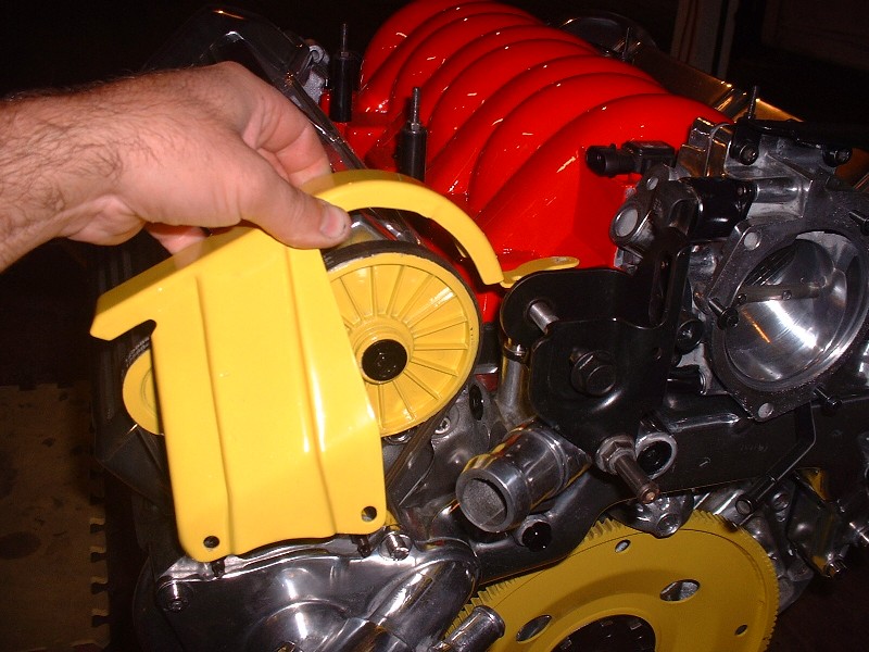
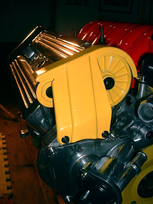
Finally to keep those probing fingers safe from whirling belts and pulleys, here’s the little pulley guard that mounts to the free end of the two tensioner mounting studs mentioned earlier.
|
|
|
|
Kento
|
OCT 04, 07:20 PM
|
|
|
|
|
Bloozberry
|
OCT 04, 09:22 PM
|
|
I forgot to mention a big milestone I reached in the last post in terms of engine rebuilding. I finally moved the engine from the stand to a floor dolly. Yay! It had to be done in order to install the water log, since the engine stand gets in the way. I also couldn’t install the rear crank seal with the engine on the stand either.
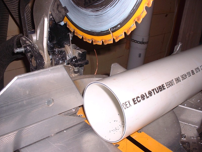
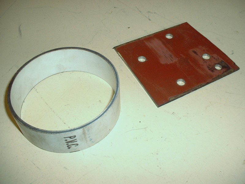
I didn’t get any pictures of the rear crank seal by itself, but the seal is quite innovative in that it’s actually a combination metal sleeve and a typical elastomeric axial shaft seal with a garter spring. The metal sleeve gets driven onto the crankshaft flange with an interference fit, renewing the journal surface on the flange that the old seal rode on by covering it up. The new seal is sized for the diameter of the sleeve, not the diameter of the crank flange. The sleeve and the seal are inseparable since the sleeve is formed with small flanges on both ends at the factory once the seal is slid on. It’s great because your new seal isn’t riding on the old worn surface. The trouble is that to get the sleeve pressed onto the crankshaft, you need to buy, rent, or make a special tool. Stealing an idea from PFF’er WAWUZAT, I made a tool from a piece of 4” PVC drainage pipe and some 1/8” cold rolled steel plate. I cut a piece of the PVC pipe about 2” in length:
The PVC pipe is exactly the right diameter to contact the outer sleeve flange of the seal assembly. So, to be able to apply even pressure to the pipe while installing the sleeve, I used the Caddy flex plate spacer to trace the outline of four of the eight crankshaft bolt holes onto a 4” X 4” piece of steel plate:
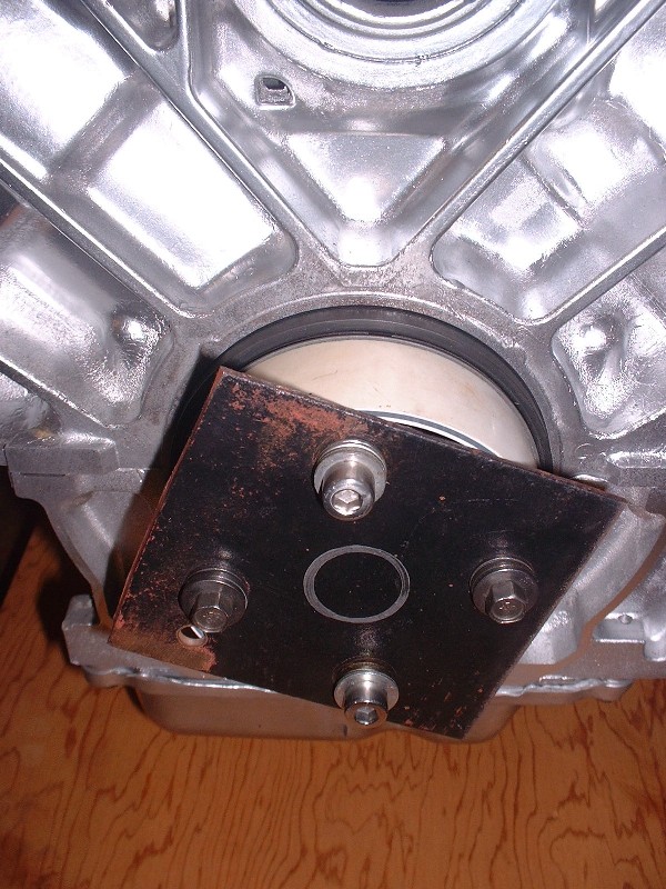
Then, by using the metal plate on top of the pipe, along with an assortment of bolts and washers, the sleeve and seal assembly can be pressed onto the end of the crankshaft squarely and under control by tightening the four bolts. The instruction that comes with the seal state that it must be installed dry, so don’t use lubricants here. You must be careful not to bottom out the bolts as you draw the seal into place because the holes in the crankshaft flange go completely through the flange. Immediately behind the crank flange is the rear bearing cap, so if you’re not careful and end up side loading the cap, you’ll warp it. To prevent this, I kept removing the bolts and adding more washers under the heads as the seal inched into place.
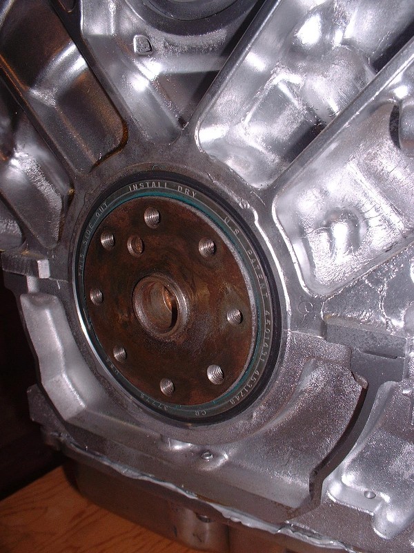
You know you’ve seated the seal/sleeve to the proper depth once it’s past the end of the crank flange by about 1/16”. Here’s a close up of the final product:
For the clutch/flywheel stack, I plan on using the Caddy flex plate as the starter ring gear, with a spacer sandwiched between the flex plate and a dual mass flywheel. The thickness of the spacer will be determined once I’ve bought the rest of the parts like the pressure plate, friction disk, and flywheel, none of which I have at the moment. But that didn’t stop me from prettying up the flex plate in the meantime.
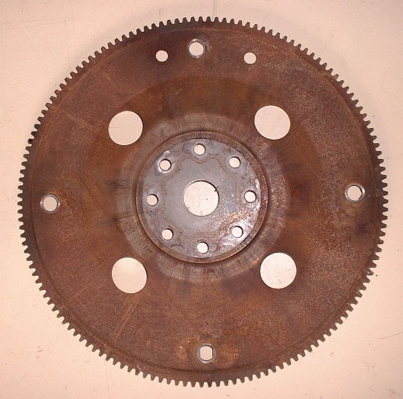
I bead-blasted it…
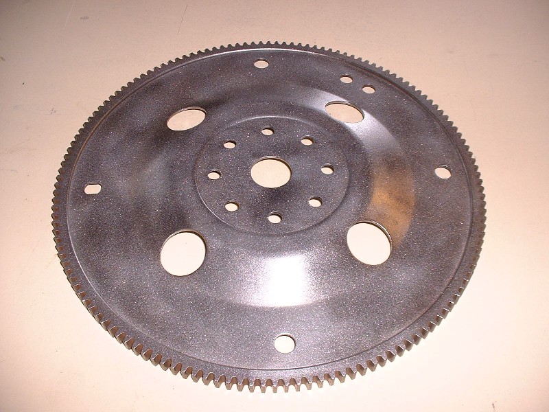
Then shot it with a white undercoat, and finally some more of that John Deere yellow paint.
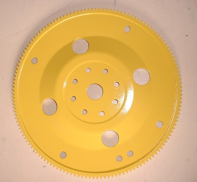
Then I temporarily installed it to get it out of the way. For good measure, I made two marks on it in line with the case half as a reference point for #1 TDC just in case the cranks turns a little while installing the front end pulleys and belt later on.

Next up: the front end hardware (or I guess that'd be the RH hardware on a Fiero). I’ve done a fair bit of research in older threads about belt routing and found some interesting stuff on relocating the serpentine belt tensioner to where the old power steering pump was up on top of the engine in the middle. So far though, all the threads I’ve seen use AC, something I don't plan to run since my car wasn't orignally equipped with it. I’ll ask here and also start a new thread in Tech asking the same question since it’ll probably get a wider audience there: Has anyone got an example of how they routed the belt on a N* without the AC compressor?[This message has been edited by Bloozberry (edited 10-04-2010).]
|
|
|
|
Gokart Mozart
|
OCT 05, 07:55 PM
|
|
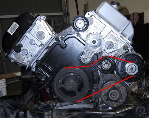
| quote | Originally posted by Bloozberry:
Has anyone got an example of how they routed the belt on a N* without the AC compressor?
|
|
If this looks like yours, the ac is the bottom right. You should be able to just get a shorter belt. Use a piece of string and follow the route to get the length.
|
|
|
|
Bloozberry
|
OCT 05, 09:46 PM
|
|
Thanks Gokart Mozart, but I also want to ditch the power steering pump too, I guess I should've been more clear. Referring to the diagram you posted, I want to relocate the tensioner (like many others have) to where the PS pump is (at the top), and eliminate the AC compressor. I know it's not rocket science, I'm just wondering if anyone else has done this that is willing to share a picture.
Edit: On second thought, I guess I'll just relocate the stock stationary idler to where the PS pump is (maybe even convert the pump into the idler similar to what IXSLR8 did), leave the tensioner in the stock location, and ditch the AC. So going clockwise from the top of the engine, the belt would come off the new idler, around the alternator, to the crank, then to the tensioner in the stock location, and back up to the new idler. That settles it. I'm good to go.[This message has been edited by Bloozberry (edited 10-05-2010).]
|
|
|
|
Jefrysuko
|
OCT 05, 10:48 PM
|
|
You only need to drive the alternator correct?
Could you get rid of everything but the alternator and then relocate the tensioner to the A/C location pushing up on the bottom of the belt?
It would look alot cleaner with the belt not being routed up to the top.
|
|
|
|
Bloozberry
|
OCT 06, 07:46 AM
|
|
Thanks for the idea Jef. I'll see if it's feasible... the only potential problem I see is that since the alternator pulley is quite small in diameter, having the tensioner pushing up on the lower belt may place it too close to the upper side of the belt for comfort.
(Edit: BTW, +'s for both of you Gokart and Jef)[This message has been edited by Bloozberry (edited 10-06-2010).]
|
|
|
|
Gokart Mozart
|
OCT 06, 10:13 AM
|
|
|
What about moving the alternator to the bottom, where the ac was? You can make a standard slot adjuster, eliminating the tensioner. [This message has been edited by Gokart Mozart (edited 10-06-2010).]
|
|
|
|
88GTS
|
OCT 06, 12:13 PM
|
|
|
Or leave the alternator and use the aircon mounting hole for a custom bracket to support a tensioner. This way you will have low maintenance, but more important, have a short belt that is tucked away out of site. I would hate to see your beautiful engine spoiled by an ugly pulley and belt loops at the top.
|
|
|
|
cptsnoopy
|
OCT 06, 02:10 PM
|
|
I don't know if anyone has looked at this but it may work. Not the optimal angles for either the tensioner or the alt but not too far off. The lower bolt on the alt pivot mount would probably require modification as it protrudes into the belt approximately 1/16". Please ignore the top idler and the ac compressor.
Charlie

|
|
|
|


