
 
     |
| LS4 / F40 swap - fieroguru (Page 212/216) |

|
fieroguru
|
SEP 12, 07:50 PM
|
|
| quote | Originally posted by pmbrunelle:
I am dissapointed that the Haltech is not "torque-based", in the sense that the accelerator pedal doesn't request a torque, and then the Haltech would figure the required throttle opening and boost pressure.
I'm working on a (non-Fiero) naturally aspirated project with a Haltech Nexus, but I want the accelerator pedal to roughly represent torque, so (in conjunction with a MAP vs. RPM vs. TPS correlation) I need to do some calculations in Excel beforehand to populate the pedal-to-throttle table.
|
|
The feature I wish the NSP had was misfire detection.
For my application there are several options to match power to available traction. I just need to take the time to play more with them.
|
|
|
|
pmbrunelle
|
SEP 13, 09:50 AM
|
|
There is an "RPM derivative" channel in the firmware.
Probably not at runtime, but maybe in analysis of a datalog you might be able to see something?
I guess that misfire detection is harder with the number of cylinders you have.
|
|
|
|
fieroguru
|
SEP 13, 07:37 PM
|
|
The brakes are done, and the total weight removed between the springs, lateral link brackets, and brake rotor swap is 8 lbs in total, 4 per side.

The new rotors also fit behind my old set of 16x7 35ET wheels:

While working on the drivers side, I found the tripot boot split, so removed, and disassembled it:


Ordered a new boot, which will be here in a few days.
|
|
|
|
fieroguru
|
SEP 21, 07:11 PM
|
|
Fiero is back together and I drove it for about an hour today on a couple of shakedown runs.
It is 8 lbs lighter with the work on the springs, lateral link brackets, and rear rotors. The drivers side axle is back to being leak free as well.
The next area for weight reduction is the smooth firewall panel. It is 16ga steel and should weight around 13-15 lbs. Switching to aluminum and 18 or 20 ga should net a 10 lb reduction.
I still need to do more mock up and ciphering on the intercoolers and head exchangers... but I was already 2 days past my 2 week limit for having the car non-running. I will continue this in a few more weeks.
Thursday and Friday this week I am scheduled off for a Route 66 car show in Springfield, IL but looking at the limited events and the 3.5 day time committment, I think I will continue with the clean up/reorg of the shop. I might go there on Saturday just to check it out and take the Fiero on another road trip, but the awards are not till noon on Sunday, it isn't worth staying the night and hanging out for that.
|
|
|
|
fieroguru
|
SEP 26, 08:01 PM
|
|
Started putting my new table to use!
Took my spare 88 front crossmember and started mounting it to the table.
- Verifed the height of the crossmember and wheel center from the ground on my car so I know their relative placements at my current ride height.
- Verified the wheel is currently centered in the front wheel well with 5.5 degrees caster.
- Shimmed crossmember 2" from the table (allows me to lower the new one if I wanted to and have better access for welding)
- Designed, cut, and welded up some hub bearing supports with -0.7 degrees of camber build in.
- Installed the hub bearing supports. They are nearly perfectly centered on the long side of the table and squared to all edges of the table (so current toe setting is 0 degrees). Each is held in place with 3 tabs and 5/8 bolts and nuts.
- Adjusted the upper a-arm for 5.5 degrees caster.


I need to reference some GM and other documents to better understand the relative elevations of the cradle attachment points and the relative angles bottom of cradle side rails, cener attachment of crossmember to frame - as when I measure both of these, they are about 1.5 degrees off. From most of the suspension design books, the lower a-arms are supposed to be parallel with the ground front to back, which would I am going to continue to use the pyramid structures to pick up the front and rear cradle mount locations from the top side.
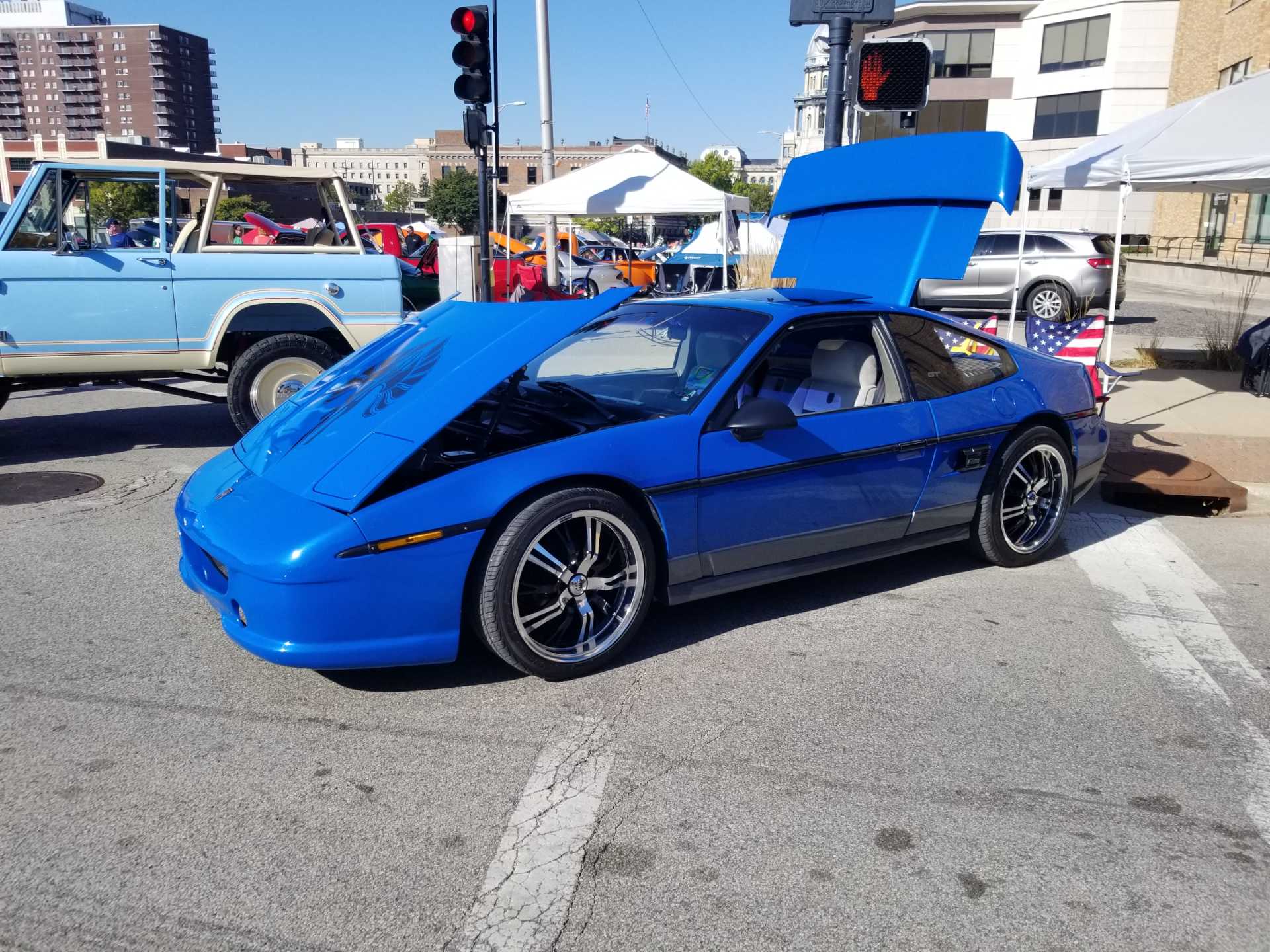
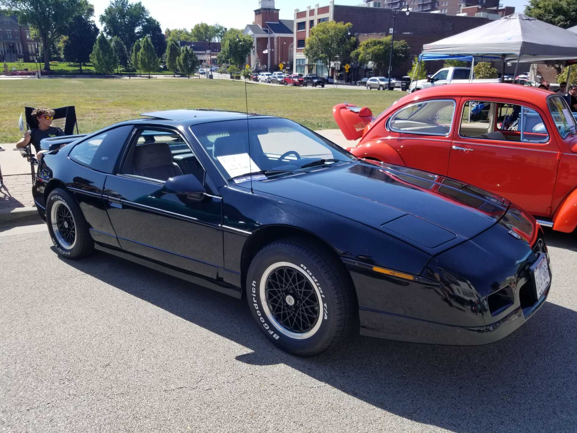
Cleaned the Fiero up some for the car show in Springfield on Saturday:

|
|
|
|
fieroguru
|
SEP 27, 02:08 PM
|
|
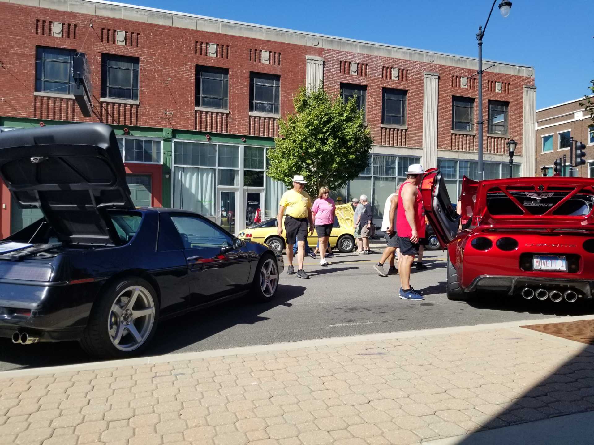
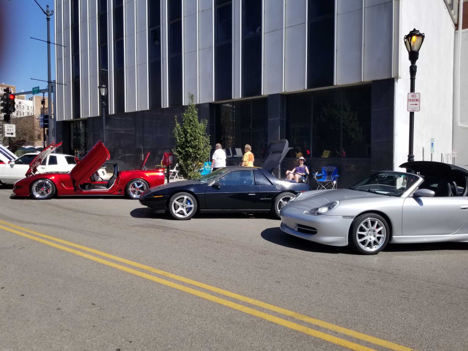
3 Fieros and lots of other cars!
|
|
|
|
fieroguru
|
SEP 28, 08:10 PM
|
|
Spent a few hours detailing the stock cradle in AutoCAD. All the suspension points are within about 0.005", but some of the crossmember shapes are appoximates. This crossmember I modified to remove the bump stop pad and trimmed the area around the spring perch. The main reason for this is to document the stock suspension setup for comparison to the new setup once I design it.

I have to be out of town Monday night to Tuesday night and have some orders to process, so it will be a few more days until I can get back to this.
|
|
|
|
fieroguru
|
OCT 11, 07:25 PM
|
|
Slowly working on making more fixturing items for the front suspension:

With the precise fixturing table, variations in fabrication of the stock front cradle are starting to be obvious. There is 1/4" difference front the wheel flange face to the frame rails side to side. The picture above is the Driverside placement, the one below is the passenger side with the fixture in the same relative location. I need to do more measuring to understand where the difference is coming from and if it is designed in or just sloppy GM fabrication.

|
|
|
|
Rickady88GT
|
OCT 11, 11:40 PM
|
|
|
I have a front member that I plan on modifying and I can see that it is also either bent or poorly fabricated. I don't even have a surface plate to measure it on. This one is noticeable with a measuring tape. I don't remember exactly what part of it is off though, it was several years ago that I last measured it for a C4 rack.
|
|
|
|
fieroguru
|
OCT 12, 08:47 AM
|
|
I need to take the front wheels off the Fiero for some new tires. While I have it up in the air, I will likely remove the two rear bolts for the front crossmember and see where the chassis side holes are.
From some preliminary measurements, the wheel flange face to the lower a-arm cross bolts were off slightly, but close. I think the a-arm to crossmember brackets are longer on the PS than on the DS.
It it wasn't "designed in", then the bolt on the chasiss would be off to the side of the hole.The rear holes are large enough for M14 bolts, but that is much too larger for some stamped steel brackets. They are likely M12 to M8 which would give them some sloppiness to accomodate this issue.
The real question is can I fix this as I design my new crossmember. At a minimum, I could add a slot to the passenger side that would allow the current hole as well as the hole that matches the drivers side.
|
|
|
|