
 
     |
| LS4 / F40 swap - fieroguru (Page 204/216) |

|
fieroguru
|
DEC 28, 04:39 PM
|
|
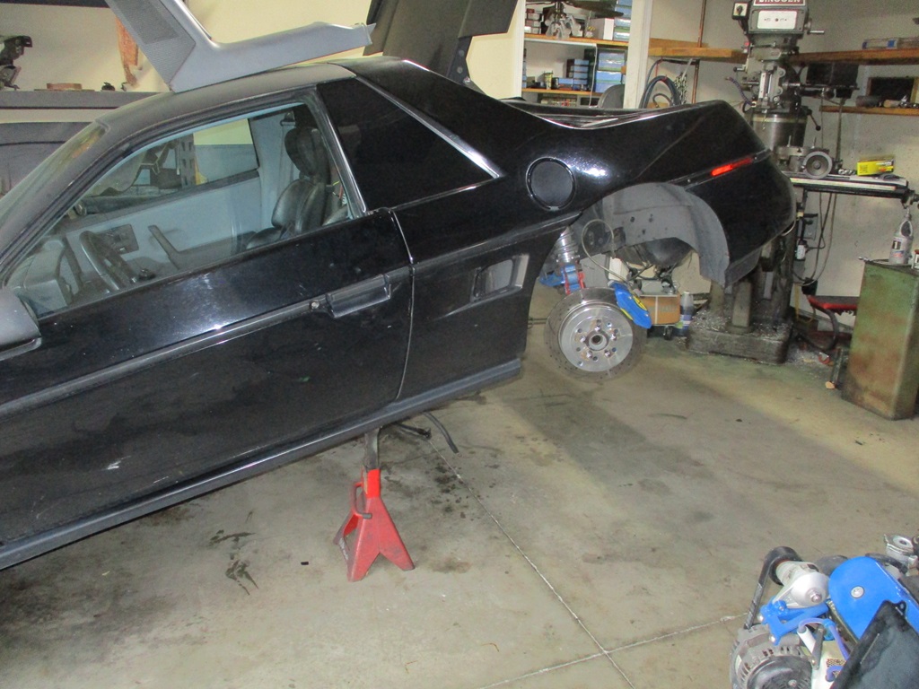
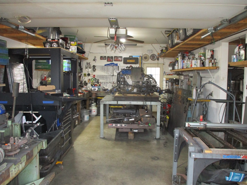
The drivetrain is out. I will move it to the other bay on Sunday and start removing the old harness and prepare for the new one.
Three things delayed the drivetrain removal:
1. The cherry picker load cell
2. Mocking up a 27x9x4 intercooler and verify fitment in front of the forward engine cradle crossmember. It fits, but I think I will be picking up a Treadstone TR8C intercooler vs. the cheapo ebay one.
3. Fabricating a fixture to located the harness pass through and the bulkhead where the ECM will mount inside the car.
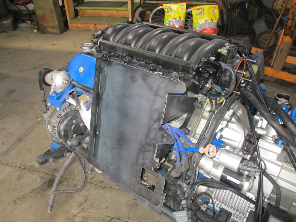
Here is the mock up of the intercooler (it was under the car and got wet earlier today):
Here is the fixture for the harness pass through as well as ECM location. This will allow more of the harness to be built and terminated on the bench vs. in the car.
|
|
|
|
fieroguru
|
DEC 29, 03:34 PM
|
|
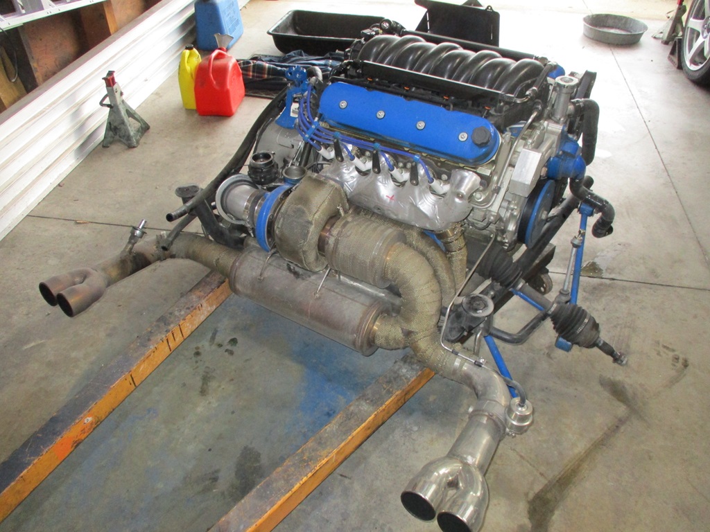
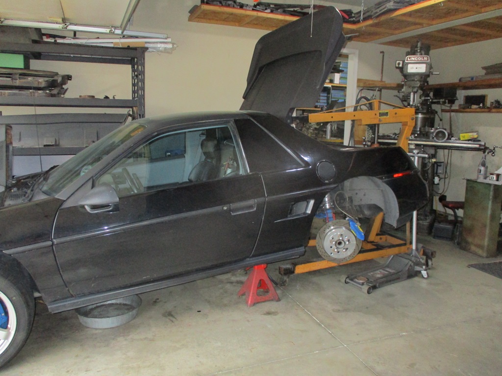
Got the drivetrain over to the 3rd bay and on the work table.
With the throttle body and hot air intake reinstalled, the total weight for the whole drivetrain, exhaust, cradle, suspension links and axles looks to be 824 lbs.
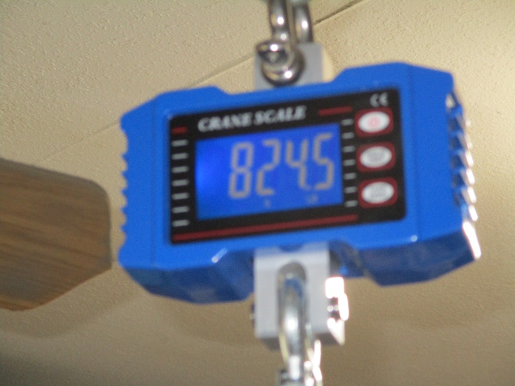
Lowered the Fiero back to a more suitable
|
|
|
|
fieroguru
|
JAN 05, 10:18 PM
|
|
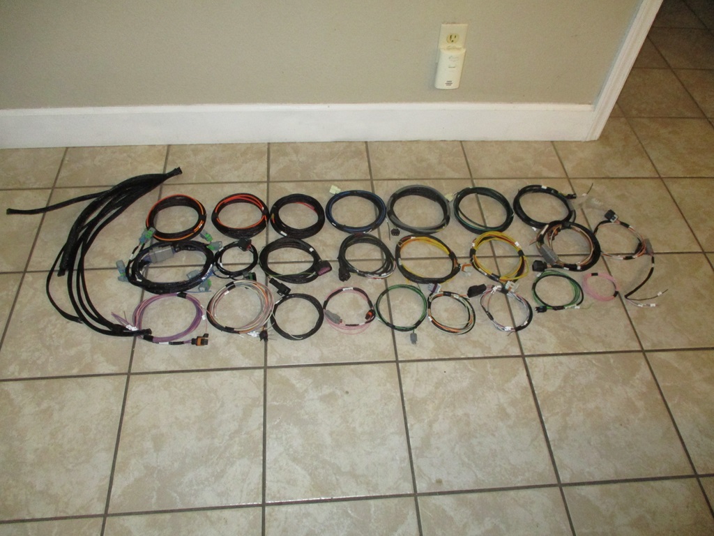
With it being cold, I spent a couple of evenings inside deconstructing the Haltech harness.
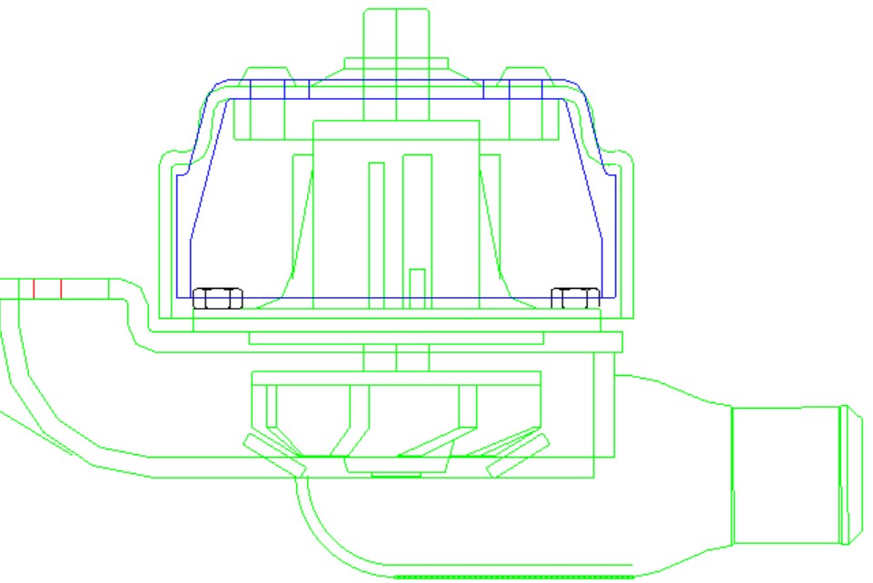
Also started working on the design for the new water pump pulley. On the HRPT the coolant temps after a couple of hours in stop/go traffic the coolant temps would creep up higher than 200 degrees with a 180 degree thermostat, which it didn't used to do. The new pulley will be about 8% smaller to increase the water pump RPM and made from aluminum to minimize weight. The blue pulley in the drawing is the proposed new one.
Ordered the pulley material as well as several of the parts for the new harness, so hoping to start making progress on them in the coming weeks.
|
|
|
|
fieroguru
|
JAN 11, 07:03 PM
|
|
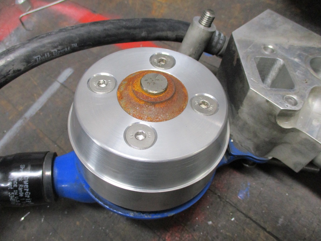
Took some time this weekend to start making the new water pump pulley.
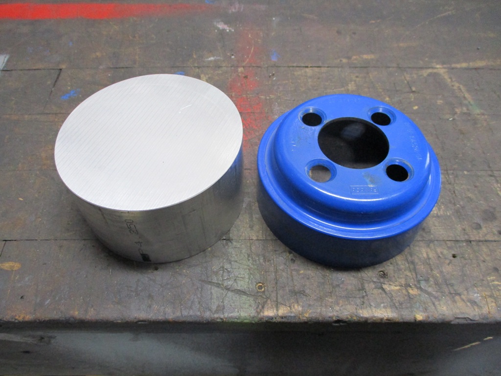
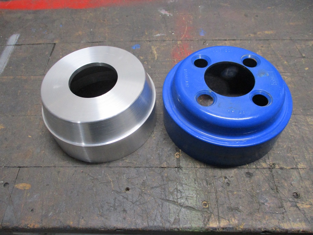

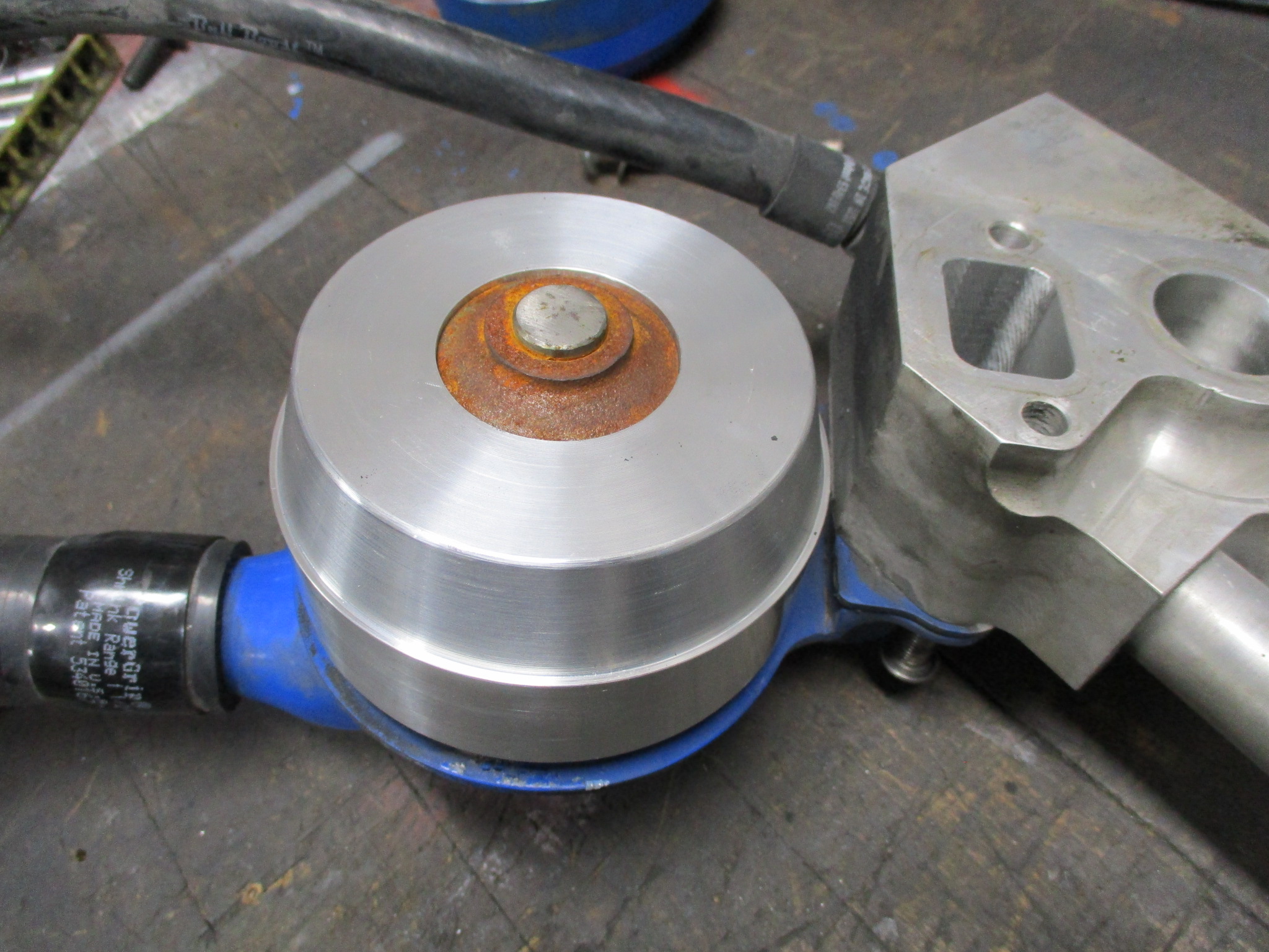
On Sunday, I will put it on the mill and drill and countersink the 4 mounting holes.
|
|
|
|
fieroguru
|
JAN 12, 08:47 PM
|
|
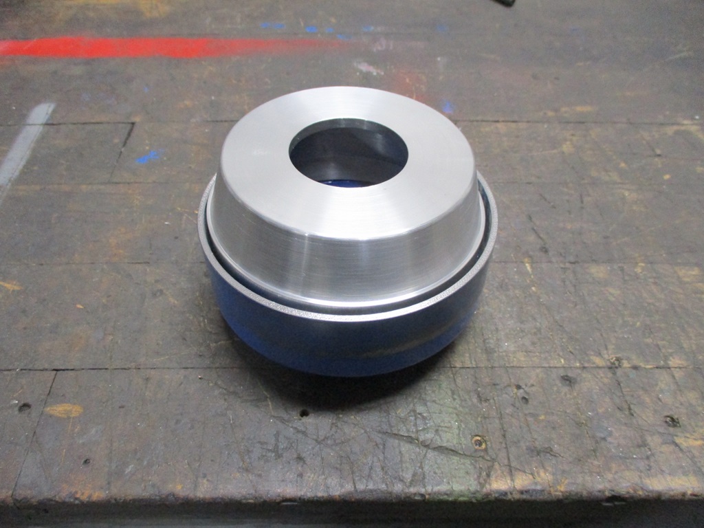
Water pump pulley is complete. Now I need to check the belt length...
Also started working on rerouting the coolant crossover tube so there is room for intercooler piping to pass by it. Should have it completed next weekend.
|
|
|
|
fieroguru
|
JAN 26, 07:31 PM
|
|
Here is a picture of the rerouted coolant return line and the new cardboard mockup of the TR8C intercooler. I still need to cut it to length, bead the ends, and weld on a new mounting tab for the driver's side.
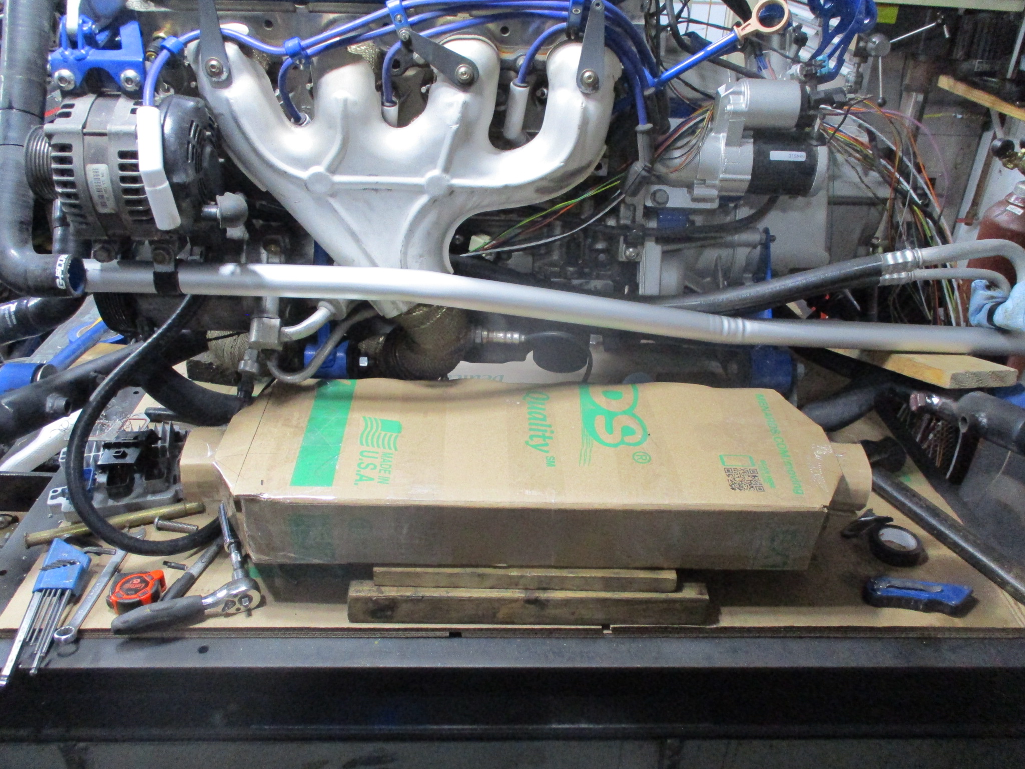
I purchased two intercooler installation kits - one with 2.5" aluminum tubing (turbo to intercooler) and one with 3" aluminum tubing (intercooler to T/B). Also a few special hoses to help get the intercooler plumbing sorted.
While I am still waiting on a few harness connector kits and some more TXL wire, I did get started with running the wires from the sensors with enough length to terminate in the console area.
Front side of engine:
DONE: Cam Sensor, Coolant (ecm & gauge), A/C Clutch, A/C Pressure, Bank 1 Knock, & Oil Pressure (gauge & ECM). Alternator to starter cable is also ran.
Still needed - Alternator connector wires to the ecm.
Rear side of engine:
DONE: Haltech W/B, Innovate W/B (only for the digital gauge), Crank Sensor, & EGT probe.
Still needed: Fab up a mount for the boost solenoid and waiting on a new connector for Bank 2 knock.
Top/Driver's side of engine:
DONE: MAP, & Fuel pressure.
Still needed: 8 injectors, 8 coils, the 6 pin T/B connector, and decide where to put the IAT sensor.
Transmission:
DONE: VSS and Reverse switch.
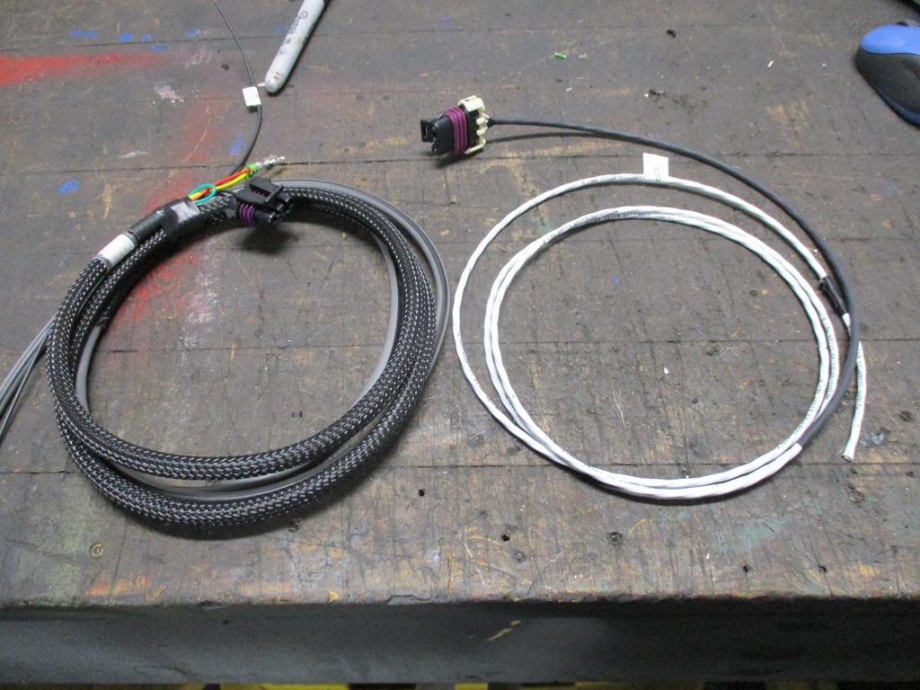
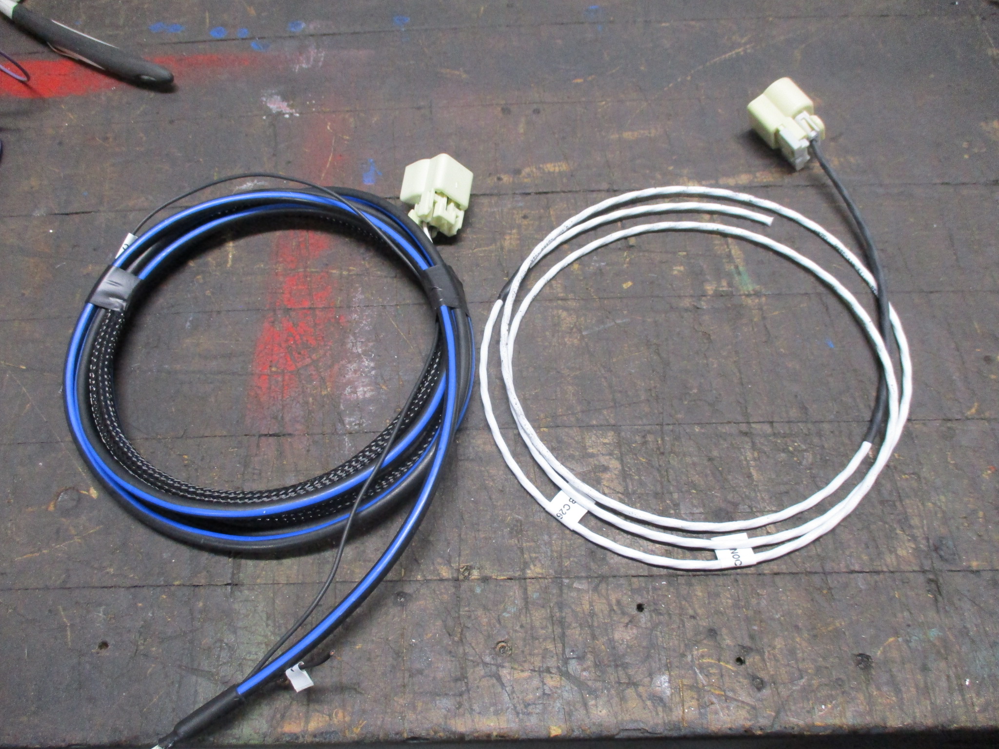
The Haltech ecm uses shielded cables for the CAM, CRANK, & both KNOCK sensors (but not the VSS). The ones they supplied had thick jackets (0.237" dia.), were not very flexible, and were 4 and 3 conductors when I only needed 3 and 2 conductors. With some digging, I found that Racespec.com had some shielded 3 conductor wire with a 0.18x jacket and more flexible. It wasn't cheap, will help keep the harness compact. I used the same wire for the knock sensors, so they have an extra conductor.
Here is the old and new CAM and Knock harnesses:
|
|
|
|
davylong86
|
JAN 27, 07:20 PM
|
|
|
All I can say is WOW! This car is insane. Been a while since I checked on your progress. Would have been nice to have your car last fall at a car show in St. Louis. Some smart ass with a 91 Vette next to me ask me if my car could beat a Yugo. You could have smoked this idiot lol.
|
|
|
|
fieroguru
|
JAN 29, 05:51 PM
|
|
| quote | Originally posted by davylong86:
All I can say is WOW! This car is insane. Been a while since I checked on your progress. Would have been nice to have your car last fall at a car show in St. Louis. Some smart ass with a 91 Vette next to me ask me if my car could beat a Yugo. You could have smoked this idiot lol. |
|
Thanks!
It continues to evolve and this coming year with boost by gear and traction control will hopefully take it to the next level of fun!
|
|
|
|
fieroguru
|
FEB 16, 02:13 PM
|
|
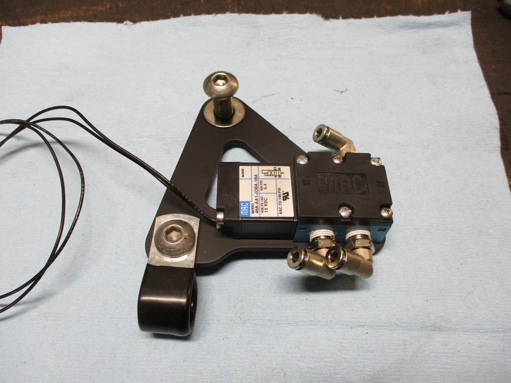
Been working on the harness the last several weeks, and got to the point of needing to mount the MAC valve for the boost controller. So spent some time making this:
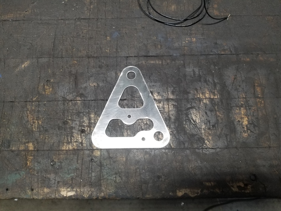
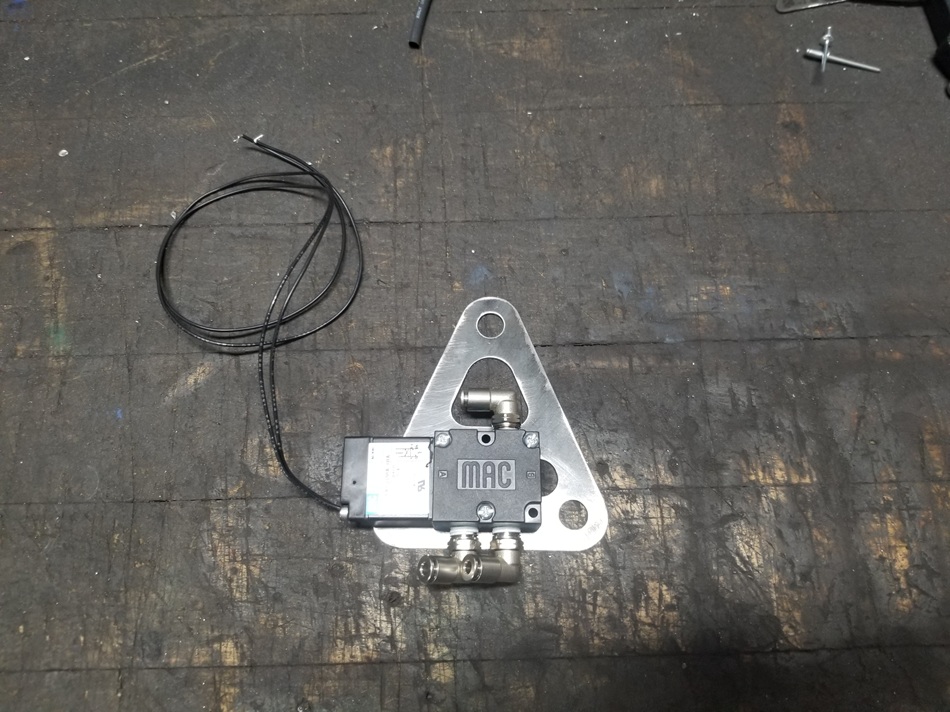
After a test fit, it needs some rework, but it getting close!
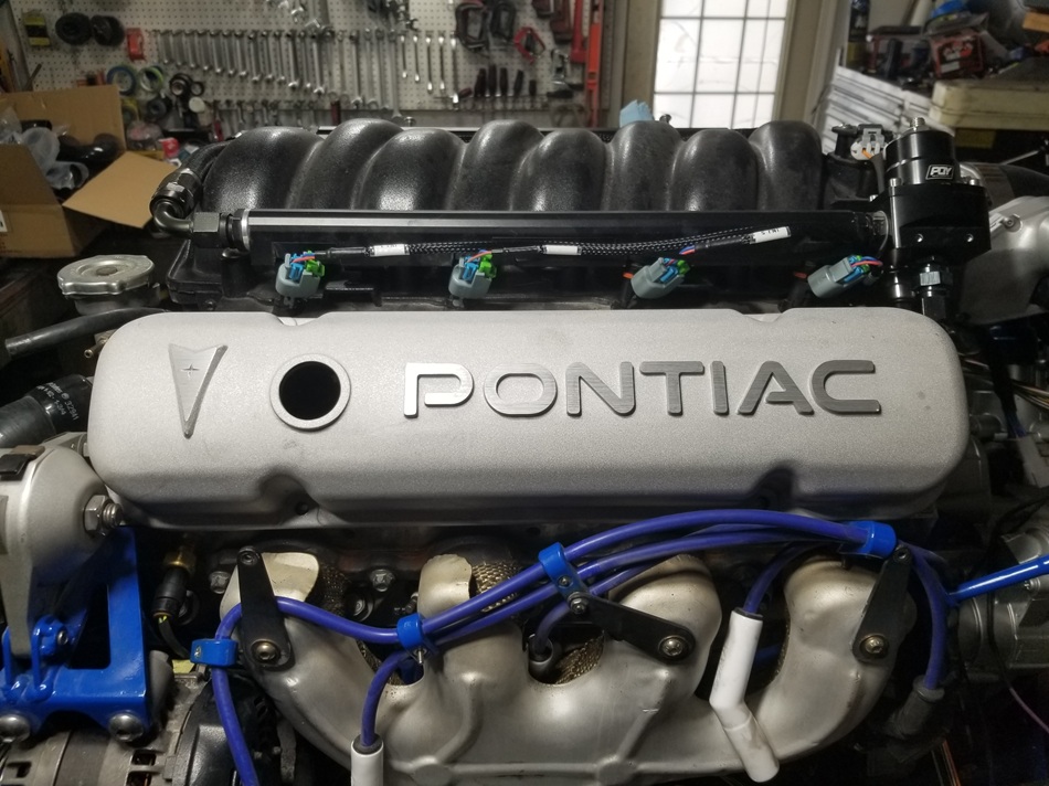
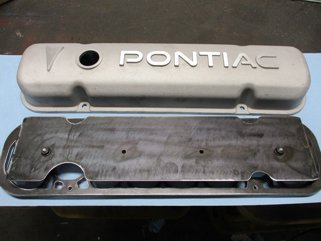
A while back, I picked up a non-LS set of valve covers that I liked. Someone made some adapters, so I purchased some CNC adapters and of course, there were basic fitment issues which make me think I got the first set. They interfered with the rocker arms, holes/dimensions not equally spaced, etc... really poor R&D in my opinion. The vendor knocked $40 off the $289 + tax.
With some file work for clearance to the rocker arms, I was able to test fit them. but ultimately I decided to make my own...
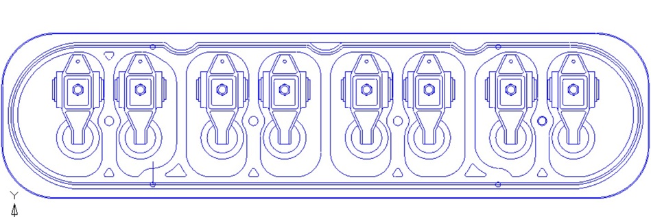
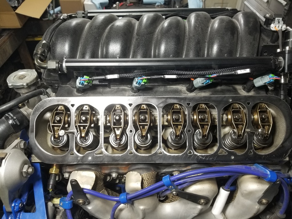
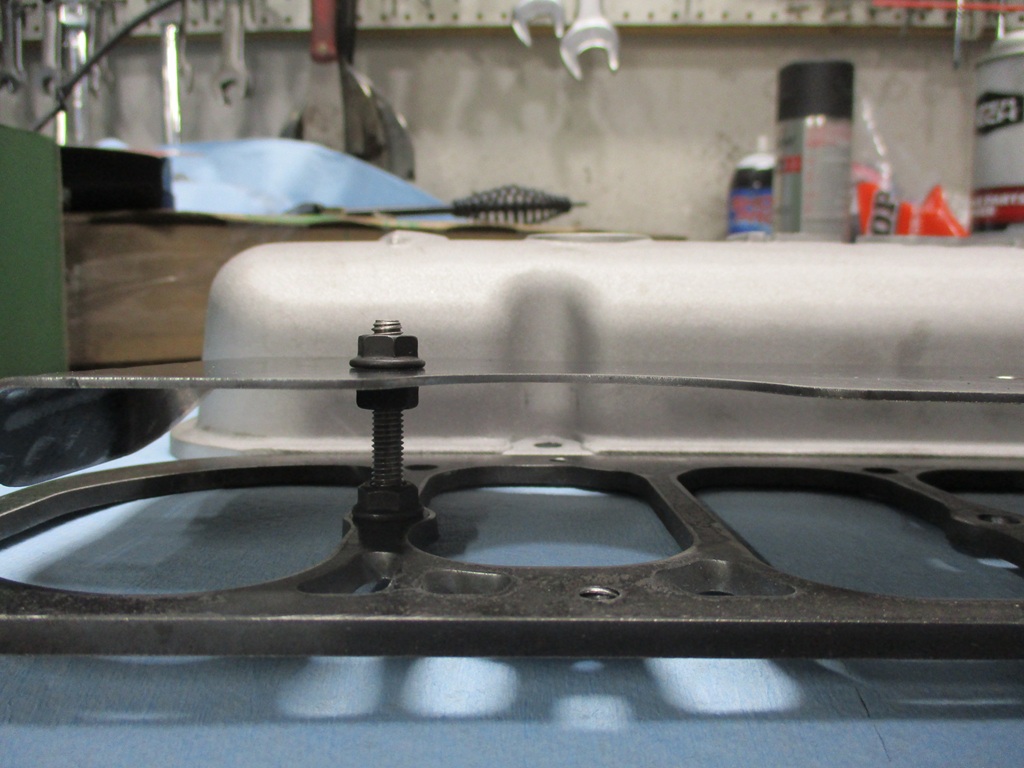
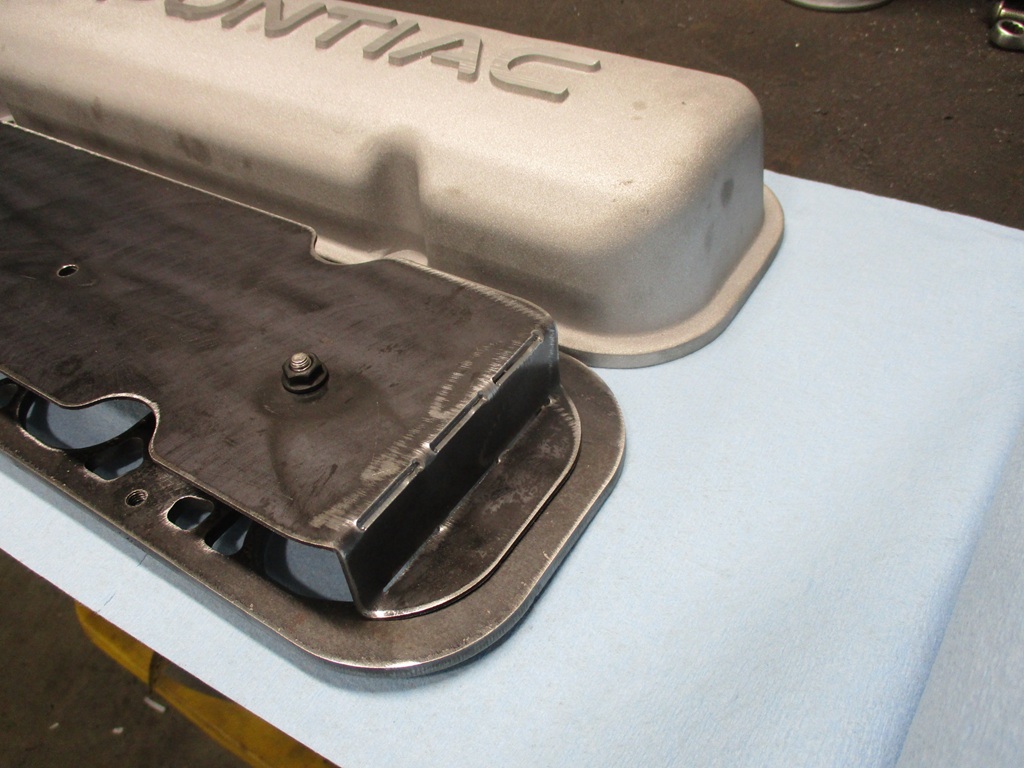
Here is a 16ga template for mockup:
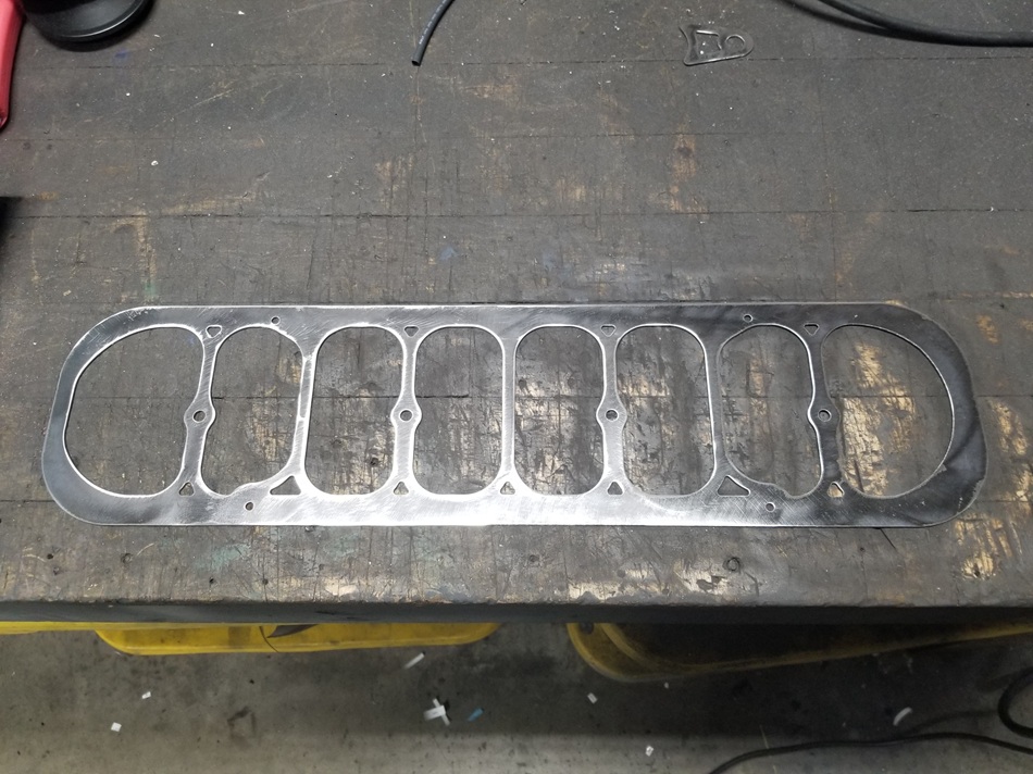
Test fit:
With the valve cover:
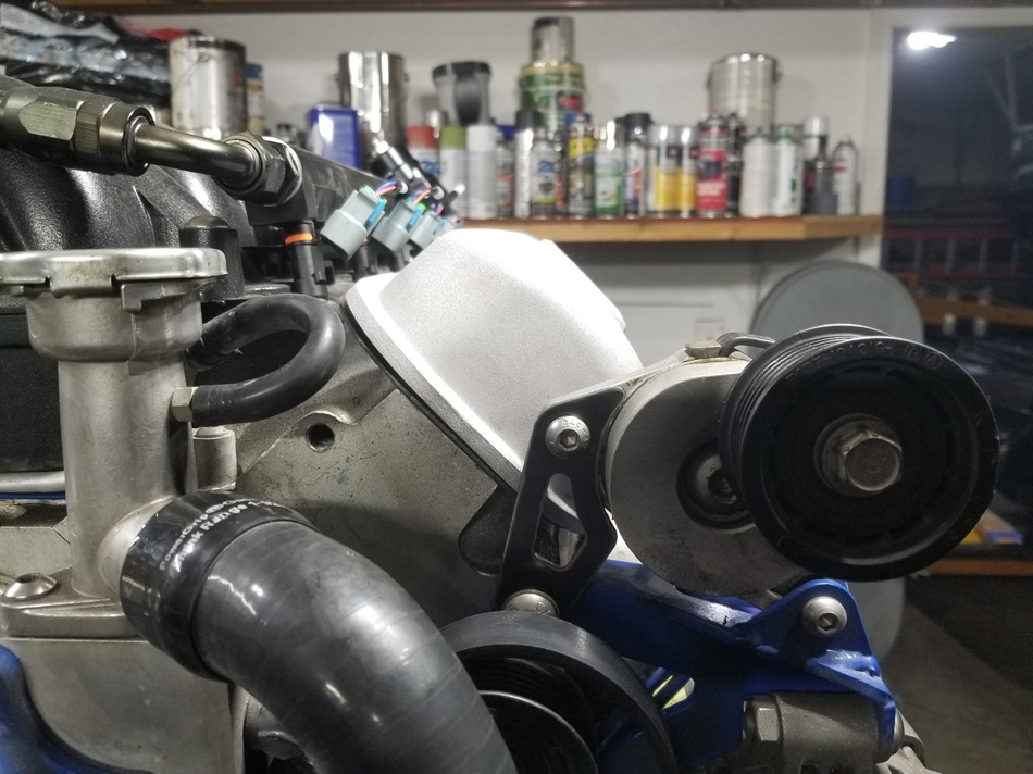
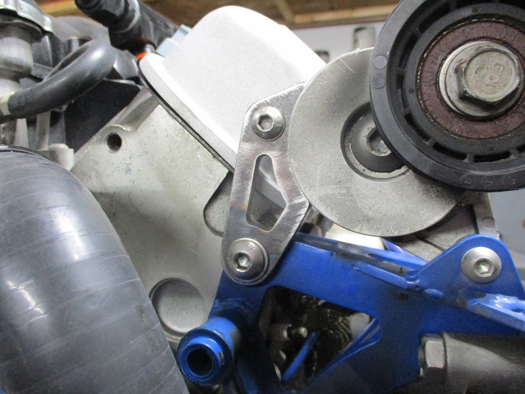
Also had to modify the tensioner bracket for valve cover clearance:
|
|
|
|
fieroguru
|
FEB 25, 08:37 PM
|
|
Tensioner bracket is done, except for powder coating:
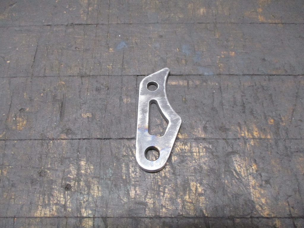
The 1/8" spacer is welded to the backside:

Installed:
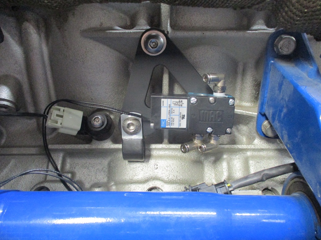
Also finished the bracket for the boost controller mac valve:

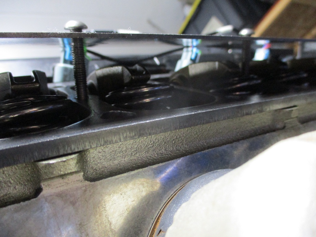
With the valve covers being about 2" above the tops of the rockers, and needing a catch can or two for the PCV plumbing, I have been playing around with an internal baffle to make the top of the valve covers work as a catch can. One end is open to below, the area by the oil fill is opened up, and then the other side is a close clearance pocket for the PCV nipple on the side. Here are some preliminary mock up pics:
|
|
|
|