
 
     |
| Blooze Own: An F355 Six Speed N* Build Thread (Page 20/126) |

|
cptsnoopy
|
SEP 14, 04:13 PM
|
|
Wow, did not see that coming... 
Charlie

|
|

|
motoracer838
|
SEP 14, 09:43 PM
|
|
| quote | Originally posted by cptsnoopy:
Wow, did not see that coming...
Charlie
|
|
What he said!!!
The known problems are bad enough, but I think I'd be calling Alan about the other issues, that's wayyyy too much to expect the coustomer to take care of given what the things cost to start with!!!
Joe
|
|
|
|
Bloozberry
|
SEP 16, 09:18 PM
|
|
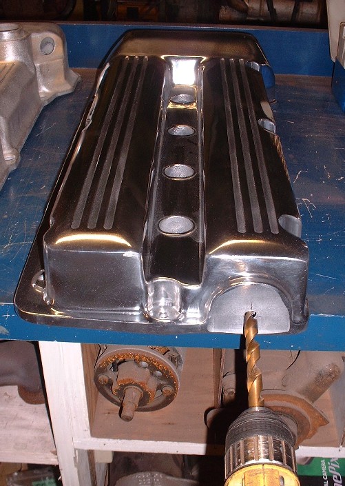
As I mentioned in my last post, the front cam cover needs to have a hole drilled through it to accommodate the intake cam on that side, which sticks out and serves as the water pump drive. My new CHRFab cam cover didn’t have the necessary hole so here’s how I went about getting it in the right place. It’s important for it to be accurate because the oil seal must be centered on the shaft or else it will leak.
The first step was to measure the location of the center of the hole on the OEM cam cover and transfer it onto the new cam cover as accurately as possible. It’s not rocket science, but there’s a monkey wrench thrown in for good measure. The OEM cover doesn’t sit flat on the workbench because of a gasket flange that protrudes below the bottom, part way around. So it wobbles as you try to measure the height of the hole. Anyways, it’s not super critical at this stage as you’ll soon see, so I drilled a pilot hole once I was satisfied.
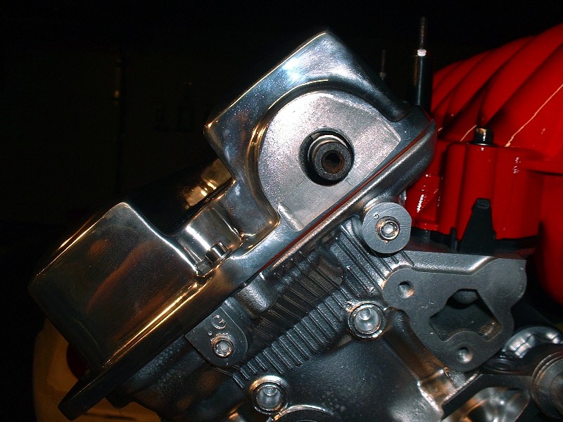
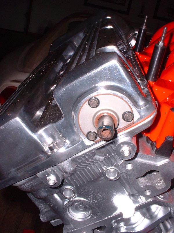
Once the pilot hole was drilled, I worked my way up to a ½” bit and then ground the hole to about 5/8” using a die grinder. I then installed the neoprene gasket, test fitted the cam cover and torqued the cam cover bolts to spec (89 in-lb). You need the gasket since it compresses to about 1/16” thick. This showed me that my original hole was off center by about 1/8” height-wise but at least I could now measure exactly where the hole had to be. To do this, I left the cam cover on and slid a large washer with a ½” ID and 1” OD onto the shaft and traced the outline onto the cover. Once the cover was removed again, I was able to grind the hole to 7/8” diameter (same as OEM), concentric to the correct center. Here’s what it looked like, torqued down, after getting the hole in the right location:
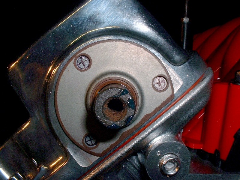
The next step is to locate the three oil seal mounting holes in the correct location so that the seal is perfectly centered on the shaft. The easiest way to do that is to install the seal on the shaft and mark the location of the holes:
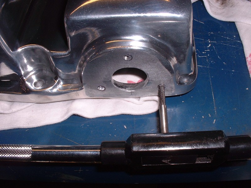
Remove the cam cover again and then drill and tap them to about ½” deep. Drill size: 1/8” diameter; tap size: M4 x 0.7. Even at that depth, the holes don’t penetrate through the material of the cover so no sealant is required, however thread locker is used on the screws.
Here’s the final installation. Like I said, it’s not rocket science, but getting that seal on so it’s perfectly centered on the shaft is important.
Finally, here are a couple shots of the covers installed on my engine. They certainly dress up the engine enough to look the part! Hopefully it’ll perform as nice as it looks.
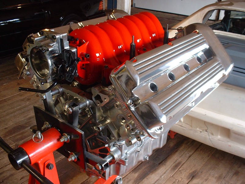
Too bad it won't be installed longitudinally like this... it would look cool that way.
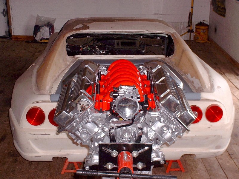
While I was taking a few photos, my 328 poster cropped up on the wall in the background, so I couldn’t help underscoring it with the top of the engine… too bad it’s not an F355.

|
|
|
|
Bloozberry
|
SEP 17, 10:02 PM
|
|
At last I only have a few “accessories” to clean up and install before I finally get to business other than the engine. I still have to order up a stainless fuel rail, and sort out some PCV venting, clean, modify and install the pulley system up front, install the oil filter mount and the water pump/log. I’ll start with these last two, first.
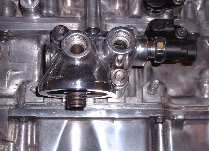
Depending whether your Northstar donor car originally had the towing package or not, your engine either has an oil filter mount with integral oil cooler ports or not. Of the two engines I bought one had the provisions for the cooler and the other didn’t. Since I’ll be running an unconventional radiator set-up, I decided to use the oil filter mount with the cooler ports to give me additional cooling capacity. I cleaned it up and installed it, but it just looked out of place and was screaming “Polish me!”
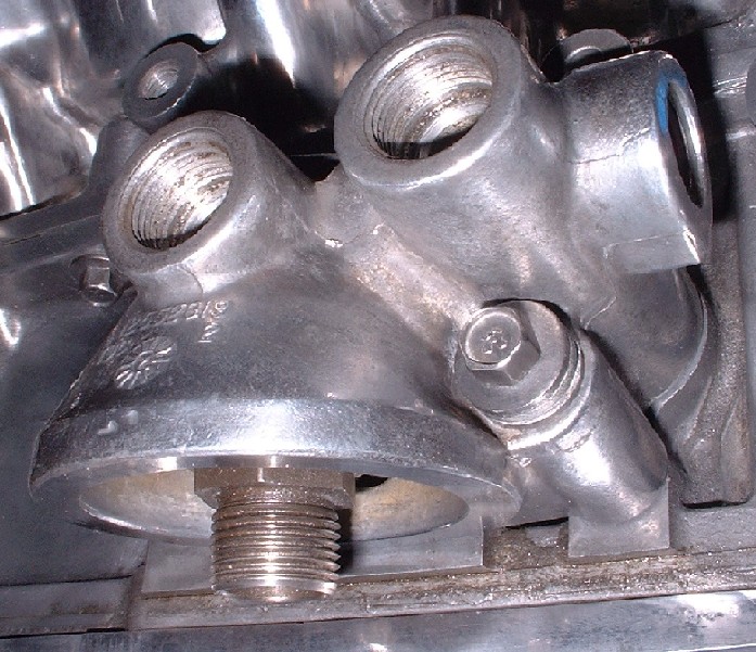
So off it came and two hours later it was ready to be installed again.
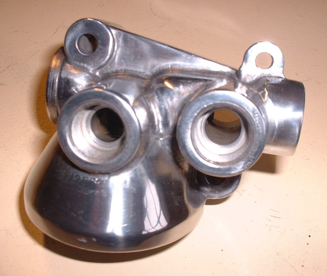
I got two new o-rings in my rebuild kit so I stuck them on before tightening the mounting bolts to 18 lbft. The oil pressure sender also gets installed into yet another port on the filter mount. It’s a pipe fitting thread so don’t forget to use some RTV.
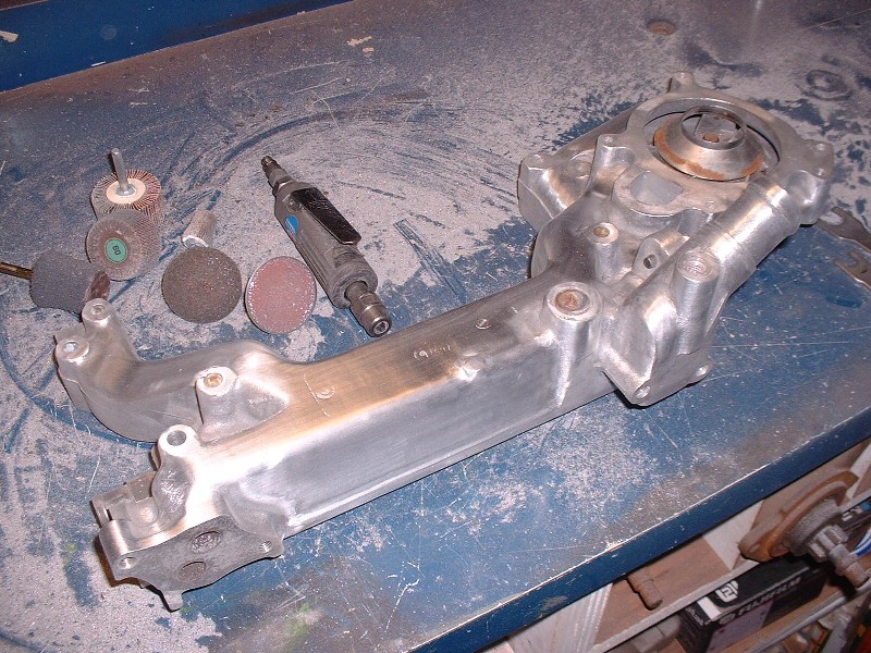
Next came a task I was not looking forward to. Polishing the water pump/log. For those who aren’t familiar with the N* configuration, the water pump is pressed into a huge aluminum water manifold that bridges the two cylinder banks at the back of the engine. It’s so long that many people refer to it as the water log. Here’s what it looks like off the engine.

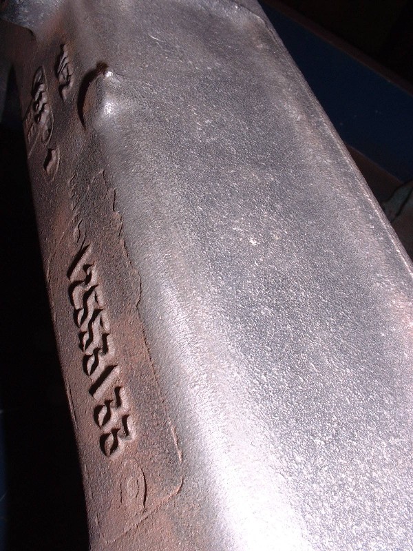
Up close you can see that it’s a rather rough sand casting with lots of raised, mismatched seams, manufacturing stamps and cast-in time, date, and part number stamps. Luckily not a lot of it is seen, but enough that if I didn’t polish it, it would look like I got lazy.
Today I started the polishing process by smoothing the water log out as much as possible. To accomplish this I broke out a handful of rotary sanding disks, flapper wheels, and grinding stones. It’s a messy job requiring safety glasses and a mask because the aluminum dust will end up in every one of your bodily orifices if they’re not covered… (yet another reason not to use a grinding wheel in the buff!) J At the stage shown in this picture I’ve used mostly a 3” and a 1” diameter 60 grit flapper wheel to get the pebble finish smooth and to remove the casting lines. Next up will be a special scrubby-type material buffing wheel to minimize the sanding marks, and then hand sanding… ugh.
|
|
|
|
rourke_87_T-Top
|
SEP 21, 05:47 AM
|
|
|
That Nylon intake looks really nice painted red, I didn't think it could be painted. You have been making a lot of progress on the engine, it's looking really good with all that elbow grease. I added to my favourites .
|
|
|
|
doublec4
|
SEP 21, 10:17 AM
|
|
|
This has to be one of the most detailed and well documented build threads around! Looks great!
|
|

|
motoracer838
|
SEP 22, 08:08 PM
|
|
Arrgh, oh man how I hate polishing!!! you sir have more patience than I, it looks awesome.
Joe
|
|
|
|
Icelander
|
SEP 23, 12:06 AM
|
|
|
Is that water log a single unit with the pump? If you have to replace the pump, will you have to polish another log? [This message has been edited by Icelander (edited 09-23-2010).]
|
|
|
|
cptsnoopy
|
SEP 23, 12:21 AM
|
|
The pump can be replaced separately.
Charlie
|
|
|
|
Bloozberry
|
SEP 24, 09:04 PM
|
|
Thanks Rourke, Doublec4, and Motorracer... I'm addicted to positive feedback! For Icelander, there's no way in hell I would have started polishing that log if it had to be replaced along with the water pump! I can just see the look on some rebuilder's face when he got my core in for remanufacturing. I think they would have mounted it on a plaque and made it the employee of the month award or something. I'm half tempted to mount it on a plaque in memory of my long lost fingerprints! Thanks for chiming in there Charlie too.
On a side note, I got diverted from polishing the log a bit when I torqued the oil filter mount onto the side of the block. The specs say it goes on with 18 lbft but as I was tightening them, I heard two snaps! Both bolts pulled the threads right out of the block. I'm still messing around with helicoils because I accidentally drilled and tapped one hole a little crooked, so the filter mount won't seat properly before the bolts bind up. So far, drilling larger holes in the filter mount hasn't corrected the misalignment enough to solve the problem. Arghhh!
Well I finally managed to finish sanding and buffing the water log. There were a lot tricky spots on it that needed special attention and special tools. I’ve found that to get into the ½” concave radii, the best tool is a tightly wound roll of sandpaper about a ½ ” in diameter and 3” long that’s made especially for porting cylinder heads and such. You screw it on a special needle-like mandrel that fits in your ¼” shank die grinder. As the outer layers are worn off, the inner layers are exposed, so one little roll lasts pretty long. Works fast and does an excellent job in those tough-to-get-at corners. In all, I spent 12.5 hours from start to finish on this piece, and I'll be the first to admit it’s not perfect, but then again if you've ever looked into the bay of a N* Fiero, there isn't much of it that's going to be seen. So before anyone asks the obvious question, my compulsive obsessiveness made me do it.

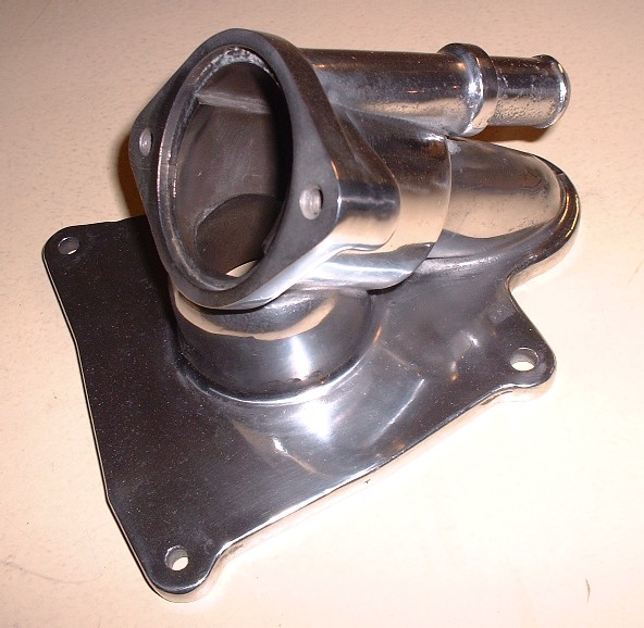
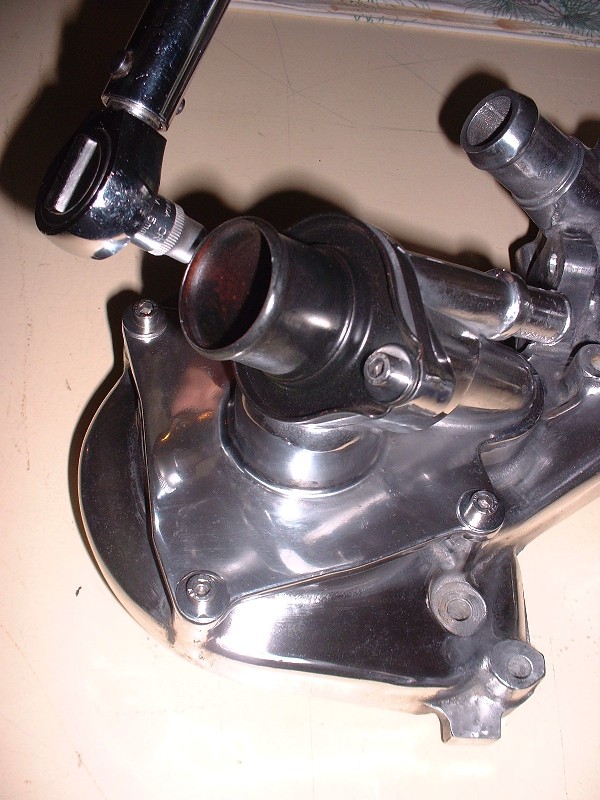
Here’s a close-up of the combination thermostat housing / water pump inlet. I personally don’t know how anybody makes any money polishing metal for others.
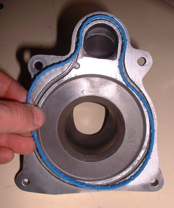
To install it on the water log, you need a specially shaped neoprene-like seal. Mine came with the master rebuild kit, and it’s a good thing, since the old seal needed to be removed from the groove to clean up a little oxidation and antifreeze deposits. It crumbled when I tried to take it out.
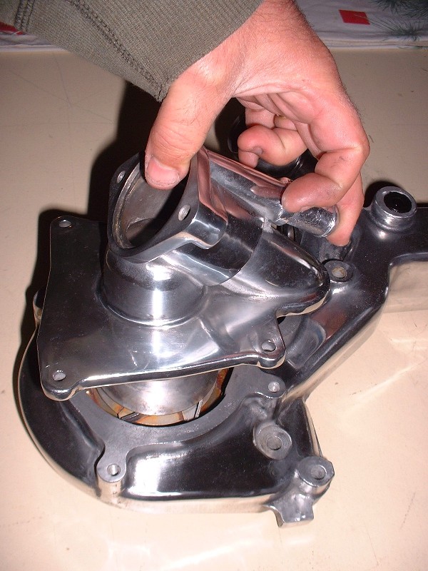
Once the new seal is in place, the housing is installed with just four 6mm bolts. They get torqued to 89 lb-in and don’t need any sealer on the threads since they don’t break into the water jacket of the pump. For the water log and it’s accessories, I decided to buy all new stainless steel socket head bolts. I take the belt sander to the fine ridges on the OD of the bolt head to get rid of them and then polish them on the buffing wheel. They look ten times better than the old steel hex head bolts and they’ll stay that way for eternity too! The nice thing about stainless is that it should minimze the galvanic interaction between the steel and the aluminum.
Next up is the thermostat itself. Interestingly, this T-stat has a small vent hole drilled though the shroud already… almost like they knew it would be a challenge to bleed the air out of this monster.
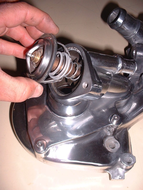
Finally, the thermostat neck gets bolted on with a couple 6mm bolts torqued to 89 lb-in as well. No additional seal or gasket is required because the thermostat comes with a rubber o-ring around its outside edge.
Here’s the pump end of the water log all built up. The eagle-eyed among you will notice that I’ve installed the dog bone mount. I'm hoping to be able to use it. The one bolt that you can see for the mount is actually a hollow bolt that taps into the water jacket so it needs RTV on the threads. The coolant hose coming from the throttle body heater connects up to that bolt.

|
|
|
|