|
| LS4 / F40 swap - fieroguru (Page 191/216) |

|
fieroguru
|
SEP 04, 06:07 PM
|
|
|
|
|
Will
|
SEP 04, 06:55 PM
|
|
|
Congrats on getting it back together!
|
|
|
|
shemdogg
|
SEP 04, 10:40 PM
|
|
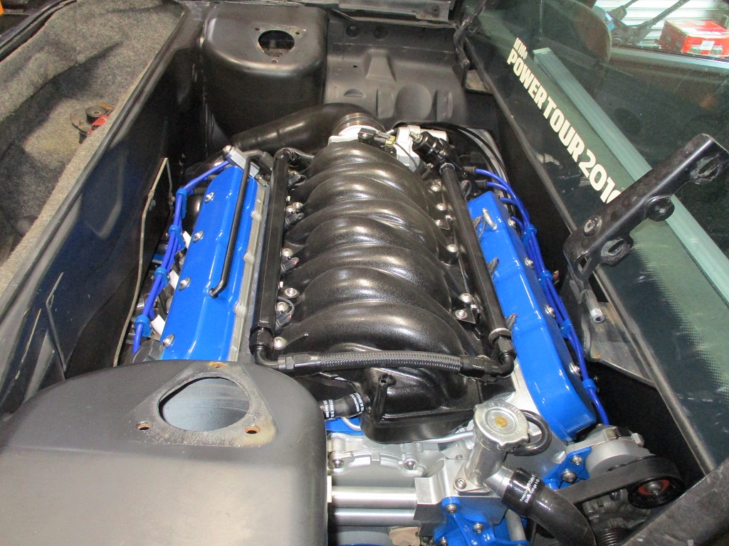
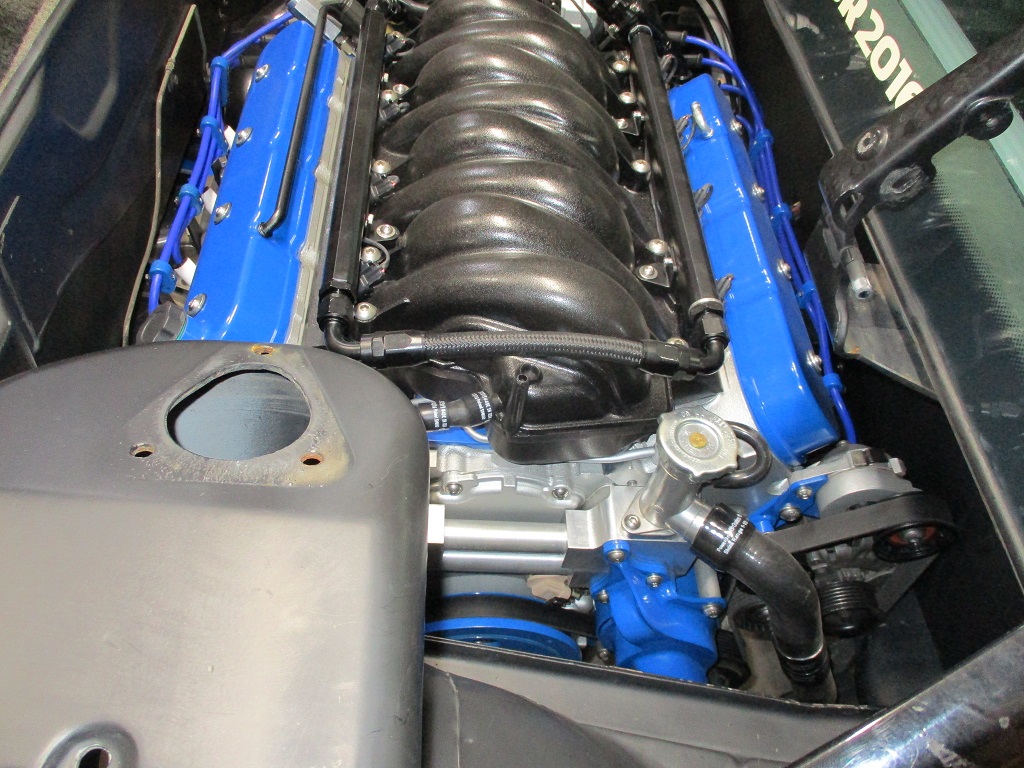
Dude that things a masterpiece wow! Where is the harness/ how did you route it? I stared at the pics looking for it lol. That is friggin clean!
shem
|
|
|
|
fieroguru
|
SEP 06, 07:03 AM
|
|
| quote | Originally posted by shemdogg:
Dude that things a masterpiece wow! Where is the harness/ how did you route it? I stared at the pics looking for it lol. That is friggin clean!
shem |
|
Thanks!
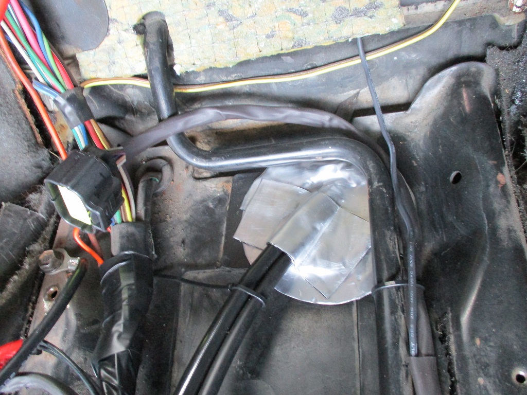
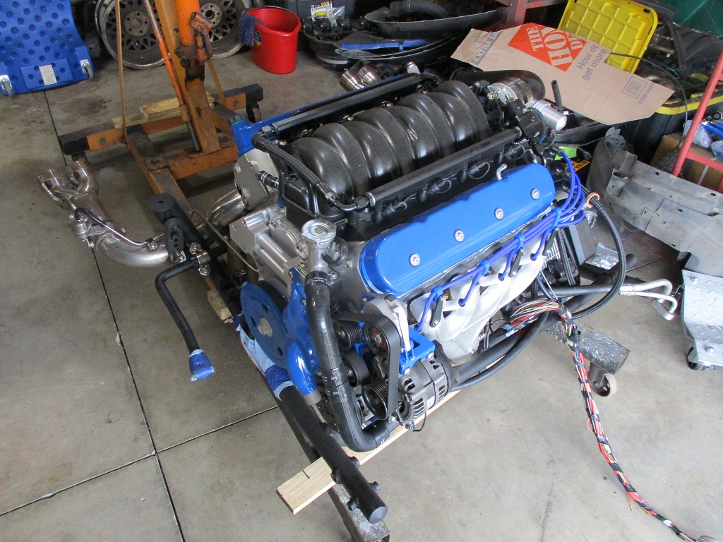
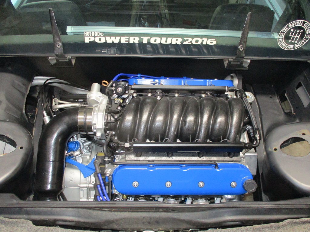
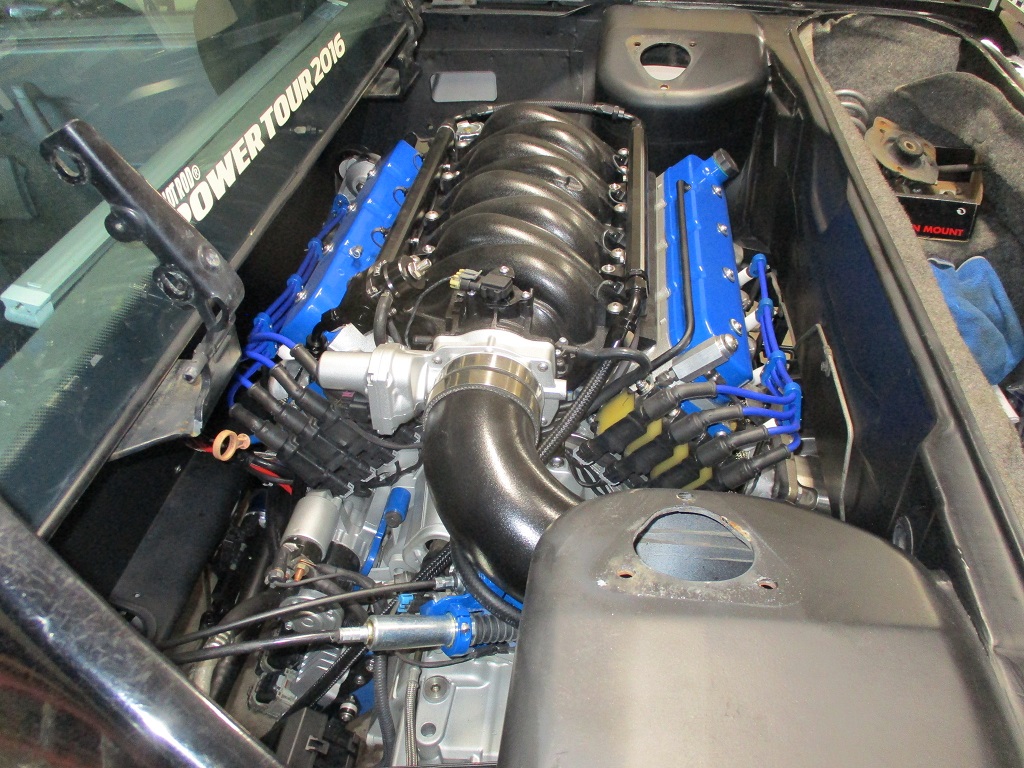
For the engine harness, using heat shrink to loom keeps the overall size of the harness minimized and allows routing under or behind other parts on the engine. Also the black heat shrink will also hide in plain sight with routed over a black part - like the intake manifold and fuel rail. For the top of the engine the harness to the injectors is routed under the fuel rails. Most of the main harness runs over the top of the bellhousing and is hidden by the coils. The throttle body is mounted upside down to the harness connects from the less visible side and the MAF sensor connection is hidden by the cold tube. When I have the option, I route as many harness wires under the exhaust and up alongside the engine block.
The other big change is I relocated where the wiring passes through the firewall. For the 500 connector all chassis related wiring (tail lights, etc) was modified to run through the double firewall panel out the passenger side and outside the engine bay entirely. All engine related wiring for the 500 connector is combined in the harness and routed through a single firewall passthrough fitting. This single firewall pass through was moved lower so it is hidden by the engine.
Page 13 about 3/4 the way down shows the 500 chassis wires going through the double firewall section and relocating the firewall pass through to a location down by the stock shifter cable pass through (which is also relocated).
|
|
|
|
fieroguru
|
SEP 10, 04:42 PM
|
|
Nothing really picture worthy...
Bled the clutch - twin disk clutch seems to be releasing and the HTOB didn't overextend, so that was good! Won't be able to test it further until the engine runs.
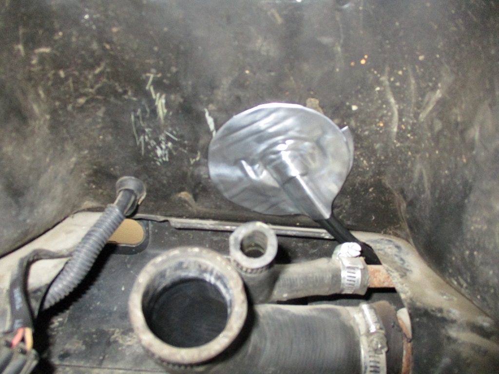
Fabbed the lower engine to chassis coolant hoses and the heater hose connector. Filled the coolant system with water for a leak check. Seems to be leak free at zero pressure, more testing will be needed once the engine runs.
|
|
|
|
nosrac
|
SEP 19, 12:02 AM
|
|
|
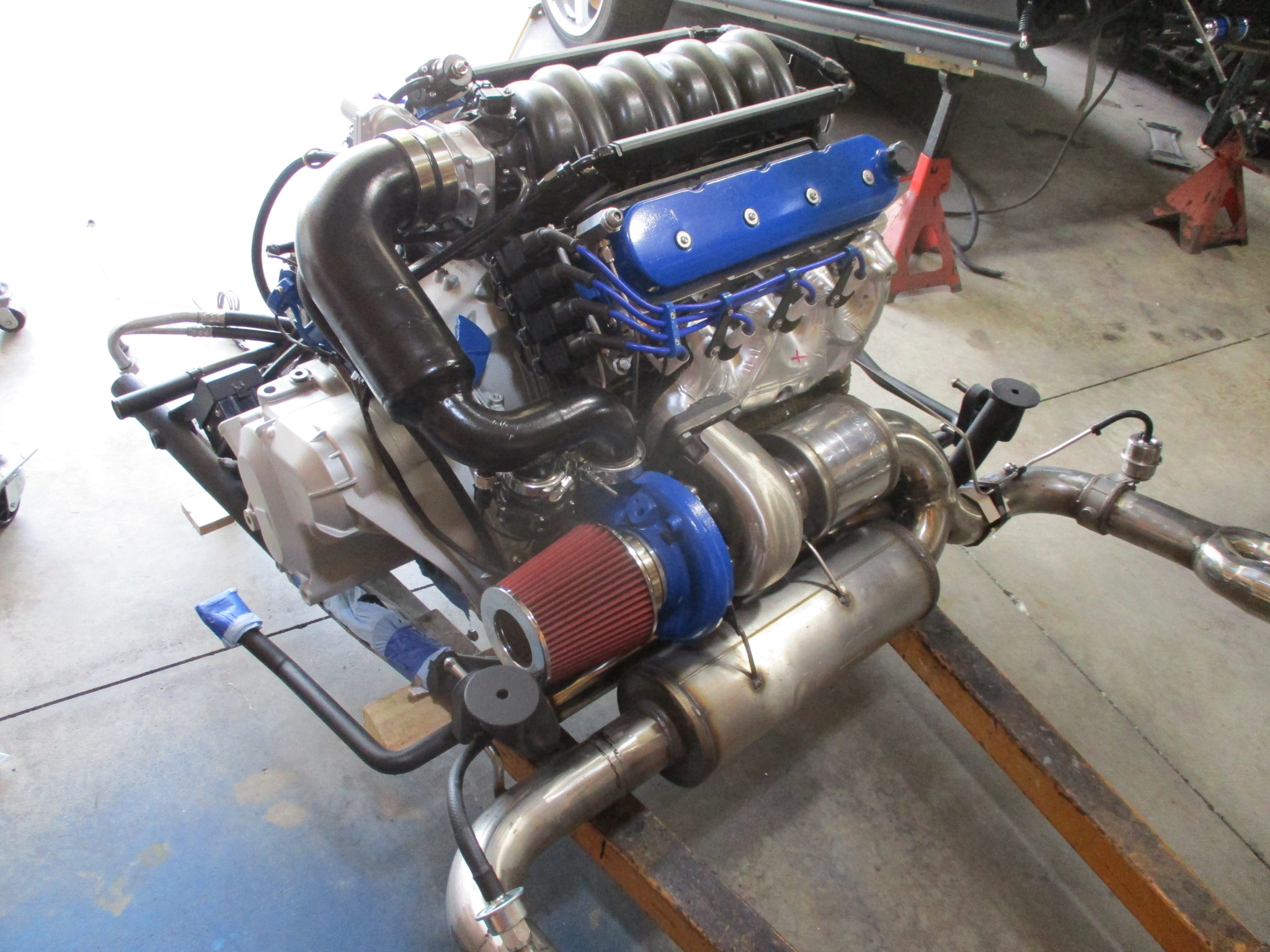
Awesome build. I mounted my turbo just like that on my build. However, you currently have a HOT air intake. I just started logging data and found out that my IAT are way to high for my liking. I may have to come up with something to remedy the temps..
|
|
|
|
fieroguru
|
SEP 19, 07:34 PM
|
|
| quote | Originally posted by nosrac:
Awesome build. I mounted my turbo just like that on my build. However, you currently have a HOT air intake. I just started logging data and found out that my IAT are way to high for my liking. I may have to come up with something to remedy the temps.. |
|
Thanks!
I am expecting my IAT to be in the low 200 - 235 degree range with 8-10 lbs of boost.
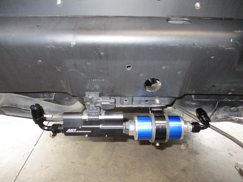
Fuel tank went in this past weekend and all the -AN fuel lines were made. Few other odds and ends on the underside of the drivetrain were also completed. All that is left is finishing up the electrical wire terminations in the cabin.[This message has been edited by fieroguru (edited 09-19-2023).]
|
|
|
|
nosrac
|
SEP 20, 02:52 PM
|
|
| quote | Originally posted by fieroguru:
Thanks!
I am expecting my IAT to be in the low 200 - 235 degree range with 8-10 lbs of boost.
Fuel tank went in this past weekend and all the -AN fuel lines were made. Few other odds and ends on the underside of the drivetrain were also completed. All that is left is finishing up the electrical wire terminations in the cabin.
|
|
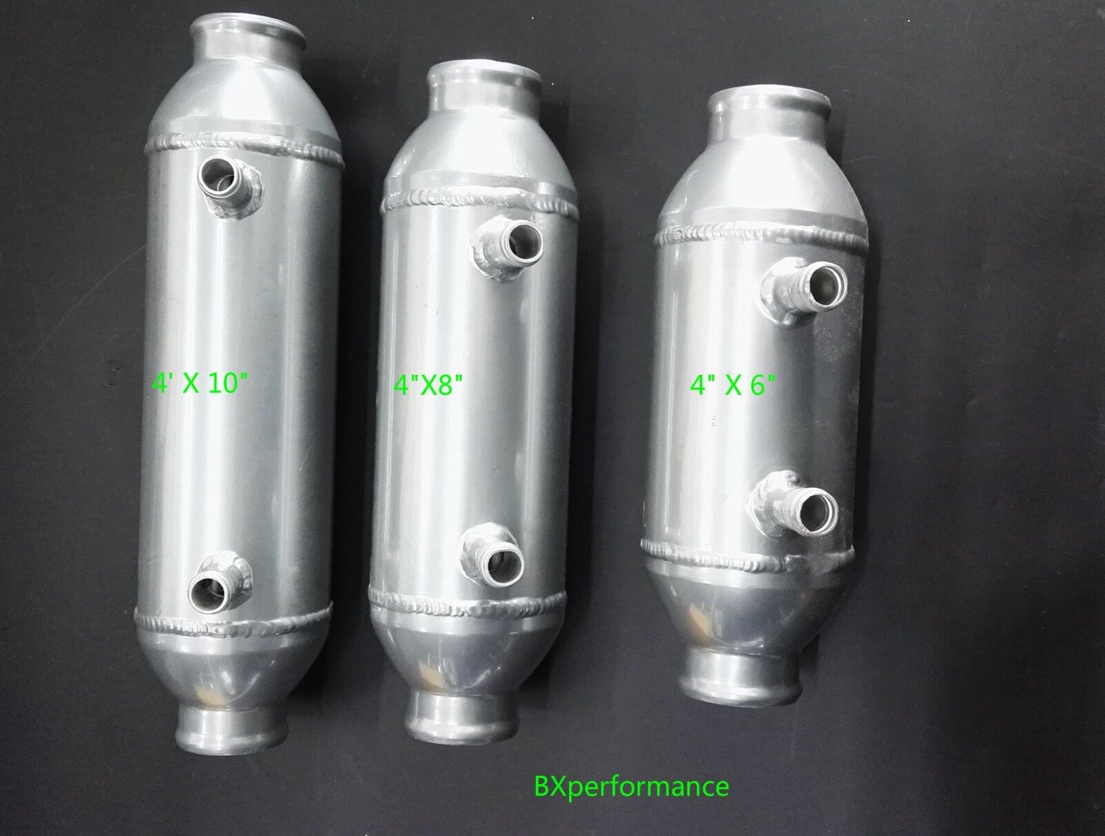
Wow, I thought 150 degrees was way too high.. This IC could help and would still fit your intake theme.
|
|
|
|
fieroguru
|
SEP 20, 07:22 PM
|
|
| quote | Originally posted by nosrac:
Wow, I thought 150 degrees was way too high.. This IC could help and would still fit your intake theme.
|
|
Right now, there are a lot of conflicting goals...
- Trying to fully offset the additional weight of the turbo to limit overall weight to 2850 lbs (was 2807 in N/A form with lighter wheels/tires), as my next round of upgrades (AWD) will add 150+ lbs, which I will try to offset as well).
- 550+ rwhp target (to start), but not a max effort build.
- I don't want the engine bay to scream turbocharged engine, while also keeping the stock trunk.
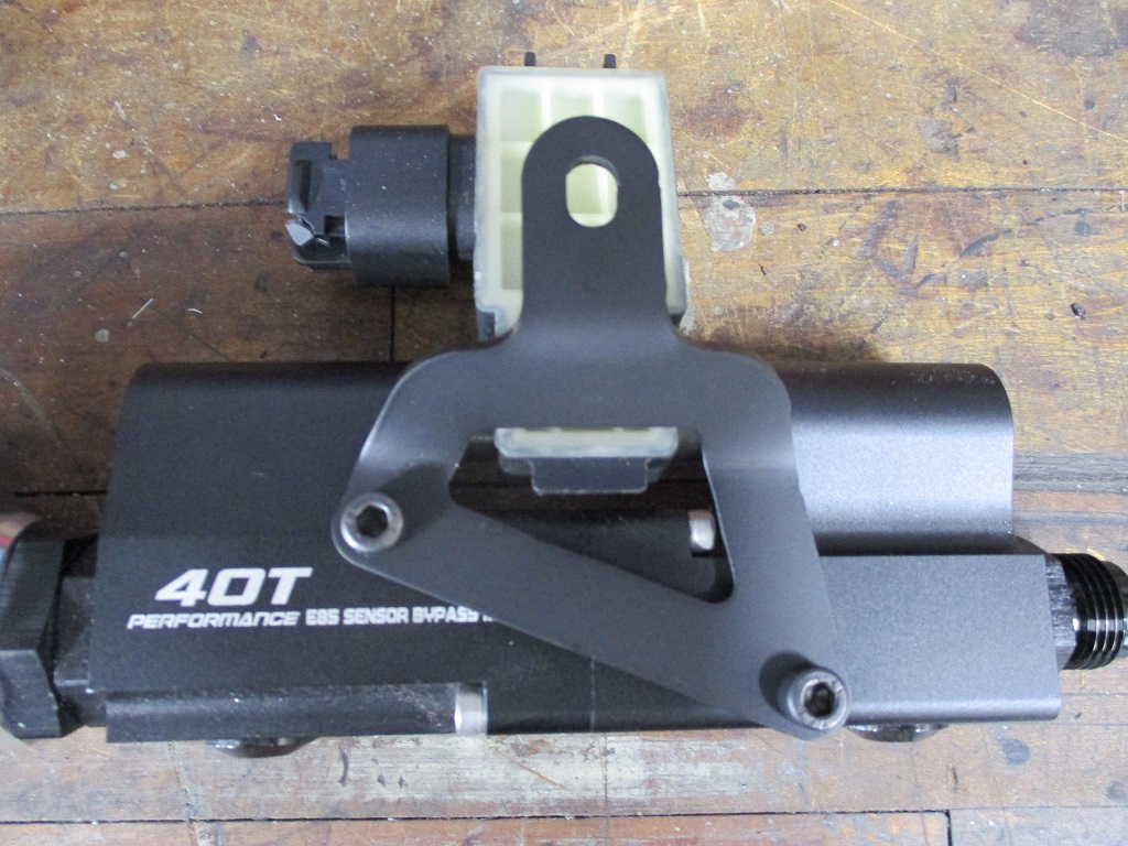
- E85/Flex Fuel conversion because allows higher IATs and I wanted to keep the turbo plumbing simple and avoid methanol injection (just another complexity and weigh challenge).
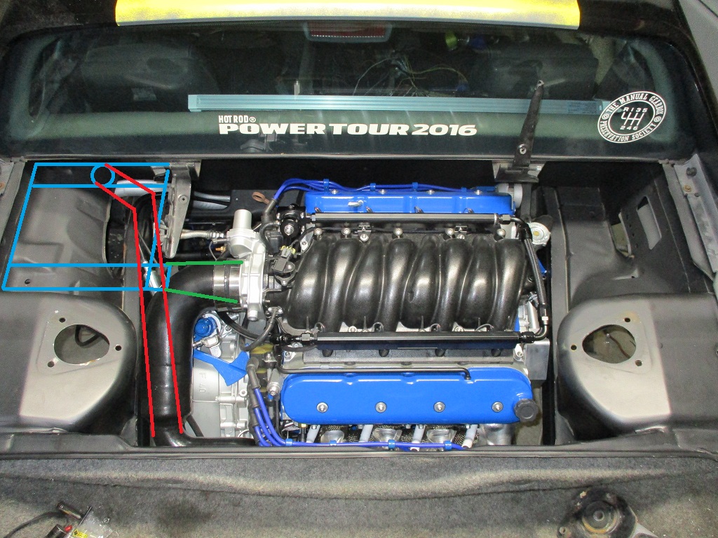
If I find I need to cool the charge pipe, I will likely just make or have made an A2A intercooler for this location. The red pipe would pass under the intercooler and enter from the bottom. The exit from the intercooler would be on the side. It would be the simplest and lightest solution and with some black paint most of it could hide in plain sight.
 [This message has been edited by fieroguru (edited 09-20-2023).]
|
|
|
|
fieroguru
|
OCT 01, 06:35 PM
|
|
Nothing picture worthy...
Still working on the wiring inside the cabin. Have loomed all the branches of the engine harness (500, 203, DBW/Cruise, DLC) and have the 500 connector wires terminated. Still need to crimp on the pins and install the connectors for the 203, DBW/Cruise, and DLC.
Getting close to the engine making noise!
|
|
|