
 
     |
| Blooze Own: An F355 Six Speed N* Build Thread (Page 19/126) |

|
Bloozberry
|
SEP 06, 09:43 PM
|
|
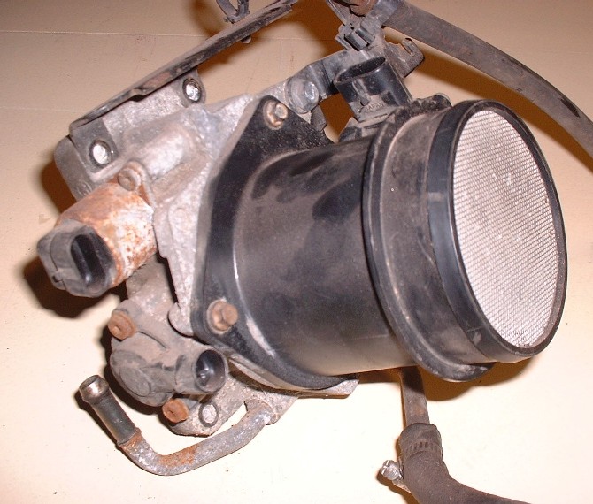
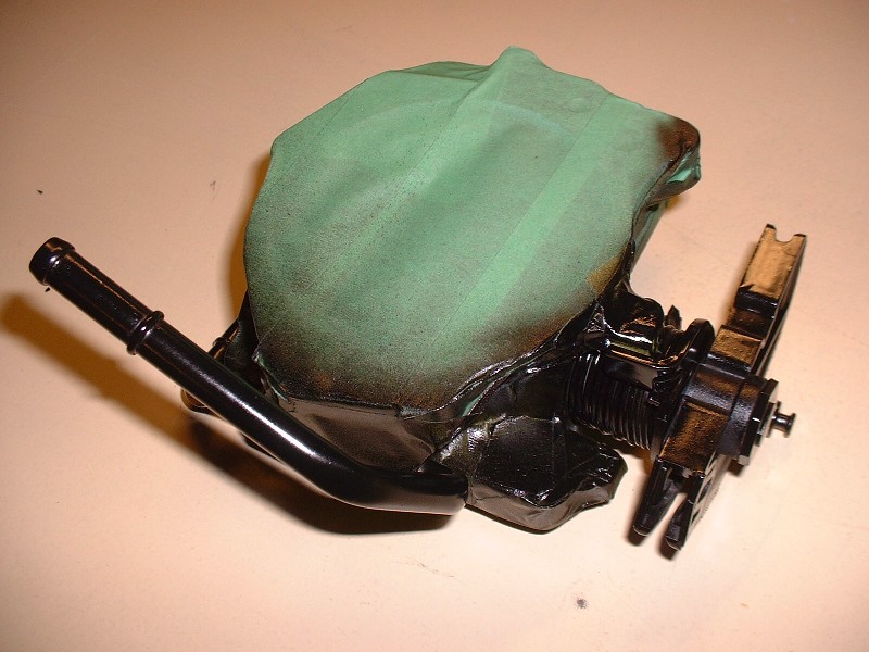
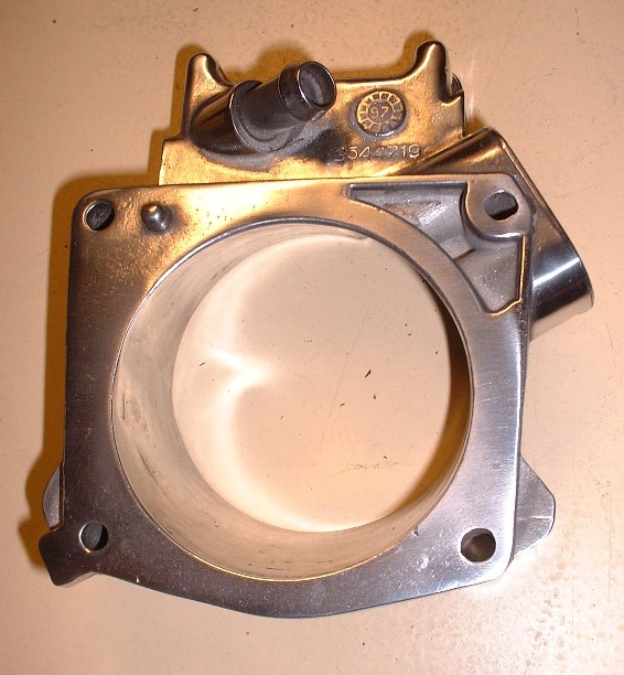
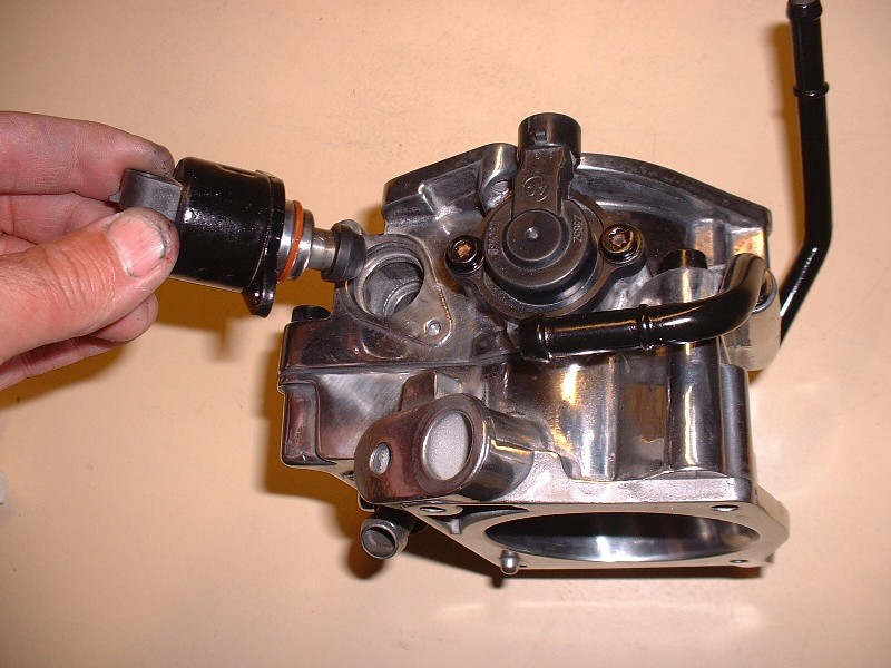
I finally managed to find some time to work on the Blooze-mobile over the past couple days. My objective was to get the throttle body taken apart, cleaned, polished, and rebuilt. I consider it a success story, but I’m getting ahead of myself. So for starters, Here’s a picture of what the TB/MAF looked like when I removed it from the intake manifold several months ago. Pretty rough looking, but I saw it as an easy challenge compared to what I had to do to the engine block to get it shiney.
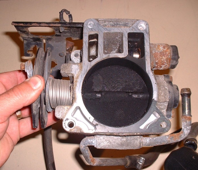
And here’s what lurked behind the throttle plate… there was enough carbon built-up to choke off an industrial incinerator in that thing. Clearly oil was getting into the combustion chambers and leaving a mess in the intake via the PCV and IAC port.
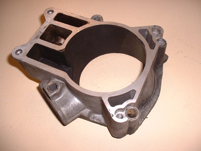
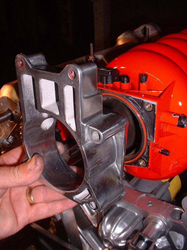
This is the other half of the TB which I call the TB adaptor since it bolts between the TB and the plenum. It was pretty crudded up with carbon too. Little did these Pigpens know that no matter how baked on their carbon or how corroded their exteriors were, they’d stand little chance of resisting the cleaning they were about to get.
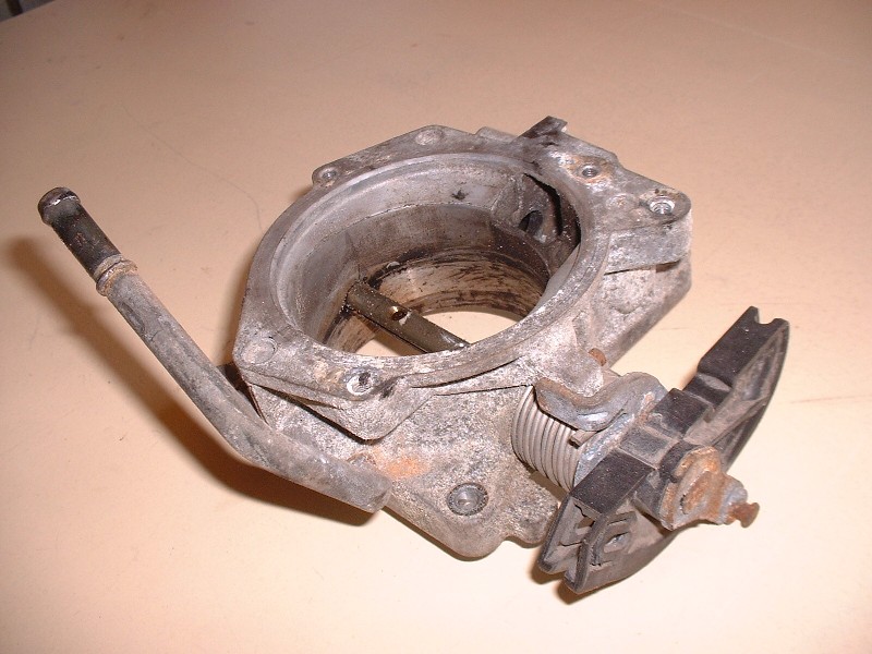
After stripping them down of all the sensitive doo-dads like IAC, TPS, throttle plate, and various seals, they were ready for the glass-beading booth. Here’s the TB ready for some deep cleaning.
Once they were bead-blasted, I spent about 6 hours sanding them smooth again (at least as smooth as I had the patience for!) and polishing them with various buffers. There’s lots of nooks and crannies on the TB so it’s impossible to get them all, even with a Dremel. But before I unveil the masterpiece, I first wrapped it up in masking tape and hit all the exposed steel with some primer and then a coat of semi-gloss black Tremclad.
And now, the moment of truth… drum roll puh-leeeease… and draw the curtain! Ta-dah!
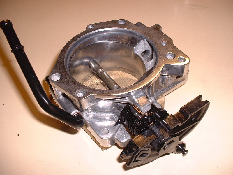
OK maybe a little too much drama, but at least it’s a lot better than it looked. With the dirty work done, the rebuilding phase could start. If you ever take one of these TB’s apart and get stuck not remembering which way the throttle plate goes back in, it’s easy. Just make sure the numbers stamped into it are facing upright and toward the MAF.
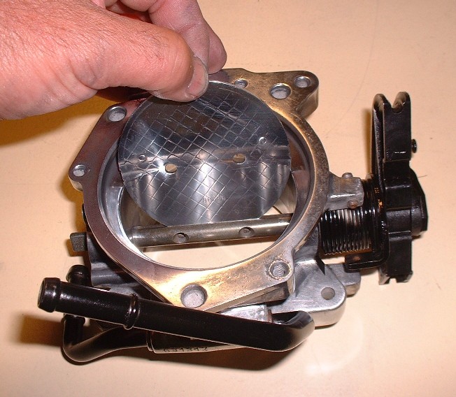
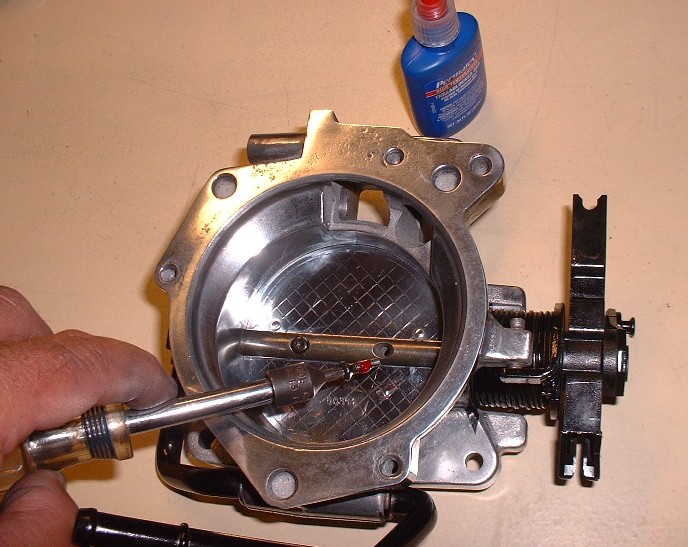
Once in place, the throttle plate gets secured by two tiny screws that are Locktited into place… they’re the last thing you want to have vibrate loose because they’ll only head in one direction if they ever come out!
|
|
|
|
katatak
|
SEP 07, 11:24 PM
|
|
|
I love clean and shiny parts!
|
|
|
|
Bloozberry
|
SEP 08, 08:43 PM
|
|
You and me too there Katatak!
Anyways, here’s the polished adapter:
A new gasket came with the master rebuild kit so I used it… no sealant required just apply it dry.
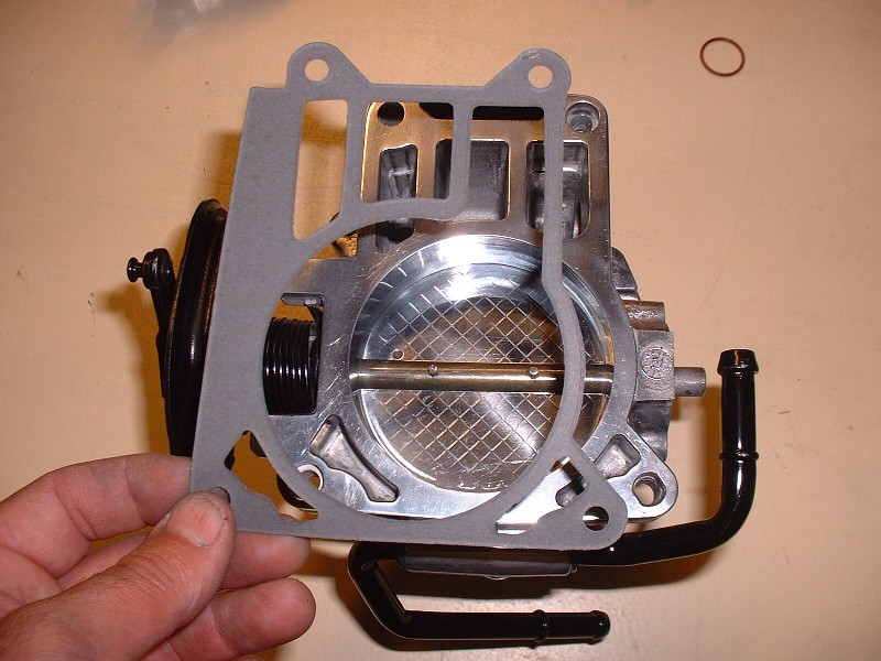
Then I installed the two halves together and torqued them as per specs. Here’s where I got ahead of myself (again) and caused some unnecessary work. Before you attach the two halves together, you’re supposed to attach the throttle body adapter to the intake plenum and then the throttle body to the adapter. The reason is quite simple: the throttle body covers up the screws that are used to attach the adapter to the plenum. I forgot about this little detail so I kept building up both halves of the TB as shown in the next few pictures. Just don’t follow this sequence if you’re doing this yourself. (Come to think of it, this’ll teach anybody who just looks at the pictures a little lesson!).
Next was the throttle position sensor (TPS). You can’t go wrong with this one… the throttle shaft is D shaped so the sensor will only go on in one orientation. It’s held on with two little screws.
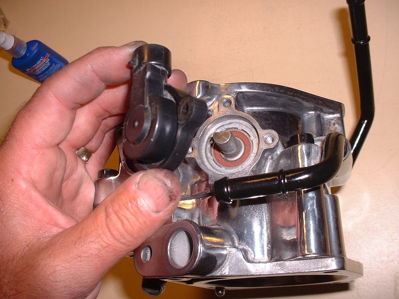
Then the idle air control (IAC) valve was installed. There’s no special instructions for the Northstar IAC unlike the Fiero one where you have to retract the plunger etc. Just put it in the hole and tighten the two little screws.
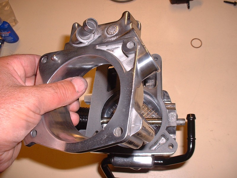
So here’s where I had to undo the part about installing the two halves together. In order to be able to install the TB adapter to the plenum, it has to be done before the TB is mounted onto it. Here you’ll see the new O-ring that also came with the master rebuild kit. It gets installed in the plastic plenum opening.
And finally the TB gets screwed onto the adapter (again). I used Locktite on all the screws to keep them from ever backing out on their own. And causing air leaks.
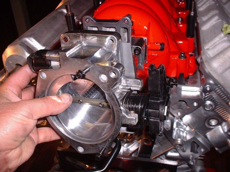
Here’s what the thing looks like once it’s installed.

Next up… I got a surprise in the mail yesterday… but all I’ll say for now is that they’re nice and shiney!
|
|
|
|
Jefrysuko
|
SEP 09, 12:46 AM
|
|
| quote | Originally posted by Bloozberry:
|
|
Show us the after picture.
After that extra gasket material started bothering you because some wise guy on a message forum pointed it out and you decided to trim it off that is. 
|
|
|
|
cptsnoopy
|
SEP 09, 03:00 AM
|
|
| quote | | Originally posted by Bloozberry:Next up… I got a surprise in the mail yesterday… but all I’ll say for now is that they’re nice and shiney! |
|
Hmmm, I wonder what that might be...? Hint, Curly recently had some pictures posted of these and yes, they are very shiny!
Of course you were nice enough to let the cat out of the bag a while ago...
| quote | | Originally posted by Bloozberry:I did order a pair of CHRFab's polished double bump cam covers... still waiting on them though. It was tough shelling out $650 clams but I think I would have regretted spending any money or time trying make the stock covers look good. |
|
Very nice job cleaning up the TB! (I spent a lot of dough just to avoid having to do that...  ) )
Charlie

|
|
|
|
Bloozberry
|
SEP 09, 07:53 AM
|
|
| quote | Originally posted by cptsnoopy:
Of course you were nice enough to let the cat out of the bag a while ago...
|
|
Party-pooper.
|
|
|
|
Bloozberry
|
SEP 10, 10:15 PM
|
|
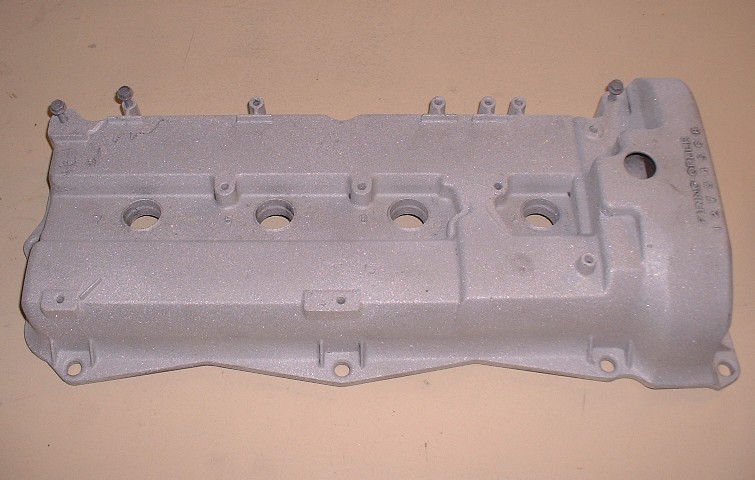
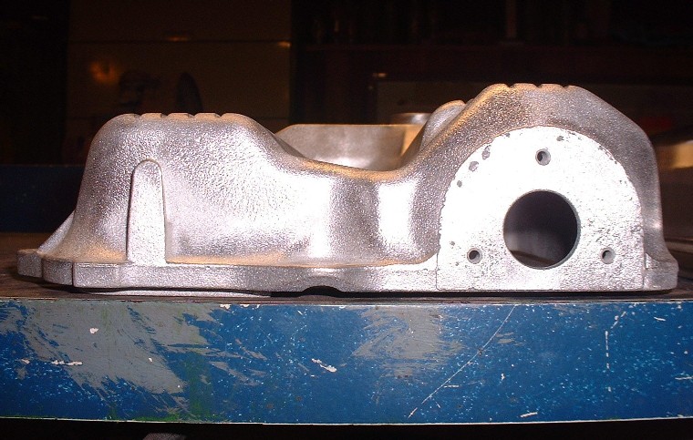
In case anyone reading this has had their heads stuck in the sand, the '93-'97 Northstar (and perhaps later years too), came with only one nice looking valve cover... the one that's seen front and foremost when you open the hood of a Caddy. This is what the pretty one looks like once it's sandblasted and ready for paint:
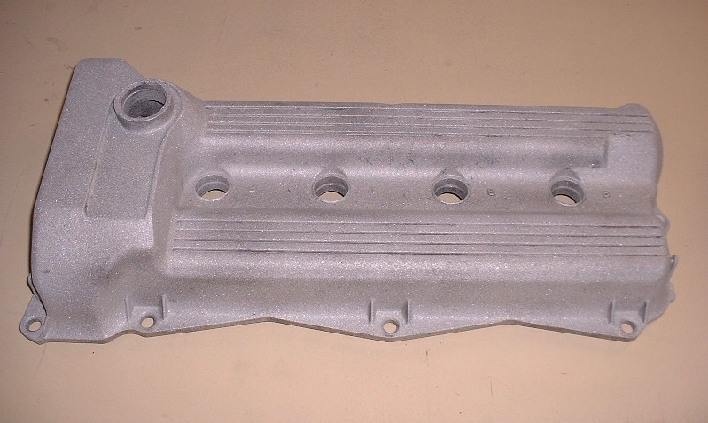
The problem with installing a Northstar in a Fiero engine bay is that the pretty valve cover is up against the back of the seats, exposing the ugly sister to show all her warts in plain view when the decklid is open.
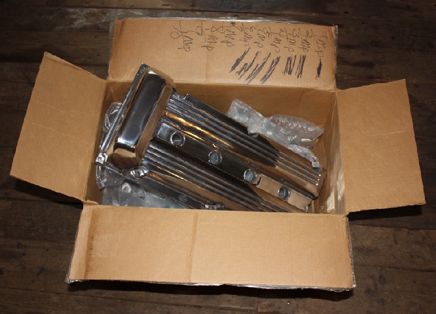
I seriously considered spending upwards of a hundred hours shaving warts, sanding the pebble finish, and polishing these two fraternal twins into something befitting of a Ferrari's engine bay, but I just couldn't picture any amount of plastic surgery that would cut the biscuit. So, I broke down and phoned CHRFab three weeks ago. A couple days ago I got a parcel-delivery notice in the mailbox. I like parcels (even if this one came with an additional invoice that I owed $107 in federal and provincial taxes before the post office would hand it over). I was surprised at how heavy the box was... secretly I was hoping that they accidentally sent me two pairs of valve covers, but that was not to be. I was happy when I opened the box nonetheless.
These are things of beauty... of course they should be for the price! They're fairly substantial castings too. I know others have posted pictures of them before, but here's a few more for the record. What you don't see because of the glare, is my smiley face reflected in the polished aluminum. And if fingers could smile, all ten of mine would be flashing their pearly whites too, happy that I spared them the labor.
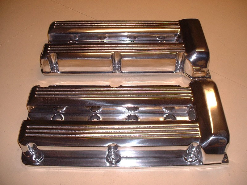
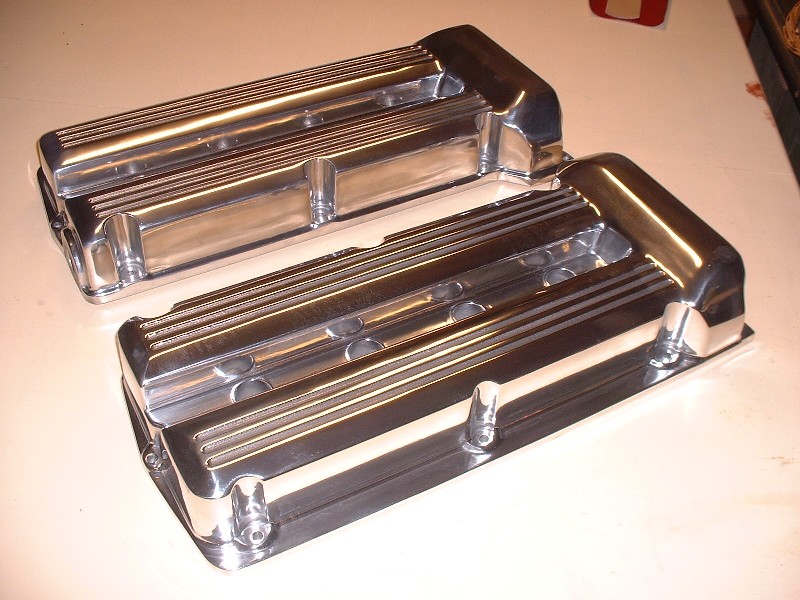
As beautiful as they are, in my next post, I'll cover a few things about them that left me wanting a little more given the premium price tag.
(Edit: PS... Thanks for pointing out that extra gasket material on the TB there Jefrysuko! It's history!)[This message has been edited by Bloozberry (edited 09-10-2010).]
|
|
|
|
cptsnoopy
|
SEP 11, 02:11 AM
|
|
I am surprised I am not blocked from your thread for being the party pooper. I was just letting you know that I actually do read it. (but mostly I look at the pictures! )
Gorgeous!, they look like they will go very well with the rest of the parts you have meticulously polished up.
Charlie
|
|
|
|
motoracer838
|
SEP 11, 09:33 AM
|
|
| quote | Originally posted by Bloozberry:
As beautiful as they are, in my next post, I'll cover a few things about them that left me wanting a little more given the premium price tag.
(Edit: PS... Thanks for pointing out that extra gasket material on the TB there Jefrysuko! It's history!)
|
|
You mean, like how to put oil in the engine??? 
I love those valve covers, but for the price you'd think that you wouldn't have to cut them up just to get oil in them and add a pvc valve. 
Joe
|
|
|
|
Bloozberry
|
SEP 14, 02:09 PM
|
|
So like I said, here are my observations on the cam covers. To be fair, I should note that I decided to accept them the way they are and I haven’t contacted CHRFab about any of these issues. The reason I’m posting this info is so that anybody else ordering a set of these may know what work may lie ahead of them, or to be sure they address these issues directly before ordering.
My initial awe at these masterpieces was tempered somewhat after examining them more closely. As motoracer838 pointed out, the first thing is that there are no ports for crankcase venting nor oil filling, but this was not a surprise since CHRFab states on their website that vents aren’t drilled so you can configure the covers as you like. For oil filling, they suggest either ponying up another $50 at time of order and they’ll weld an aluminum oil fill bung anywhere you like. If that doesn’t suit your fancy, then they suggest filling the engine using any of the four removable plastic plugs on the fronts of the heads. To keep the appearance as clean as possible, that’s what I think I’ll do.
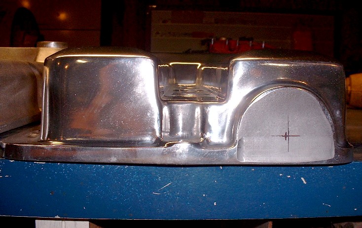
So problem #1: Something that took me a little by surprise was that the insides of the new cam covers don’t have provisions for screwing the PCV baffles into place. Here’s what I’m talking about on the OEM covers:
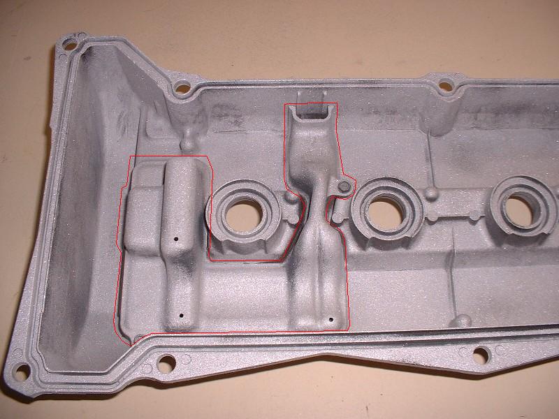
I’ll have to do a bit of research but I seem to remember having read in an older thread where oil ingestion into the intake can be caused by improper sealing of the oil baffles under the stock cam covers. Clearly if sealing is an issue, then not having the baffles at all must present a real problem.
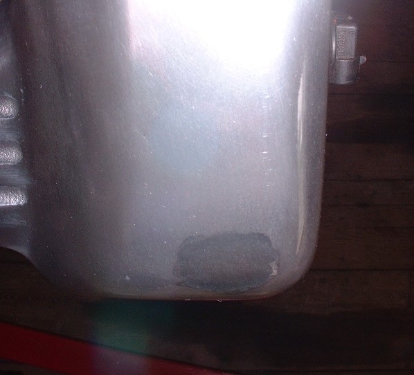
Problem #2 was that there is a dark spot on the rear cam cover… the cover that’s seen in a Fiero. It appears as though there must’ve been a casting void that was later filled by welding, and then an attempt to polish it out. The filling was well done, but there’s an undeniable blemish. You can see the area I'm talking about in the last two pictures of my last post in the bottom valve cover at the bottom right corner on the sprocket hump. Here's a close up look:
Problem #3 was that there were polisher marks in the finish of both cam covers… not from incomplete buffing, but from accidental slips with the buffing wheel. If you’re not familiar with polishing techniques, then the issue is that portions of them were polished in one direction and other portions were polished at 90* to the first part. This isn’t necessarily a no-no as long as the different portions aren’t in the same plane. The trouble happens when you slip with the buffer and contact an area that’s already been polished in one direction, with the buffing wheel at 90* to that part. It leaves buffing marks clear as day across the previously polished area. Although I was unable to take pictures of this effectively, I had to spend at least an hour re-buffing both cam covers because their buffer accidentally touched areas that had already been buffed in a different direction. For anyone without the tools or skills to rebuff them, this would have been cause of great disappointment.
On a related note, the spark plug holes in the covers were full of buffing compound. To me, this is just sloppy. I did not expect to have to clean the cam covers.
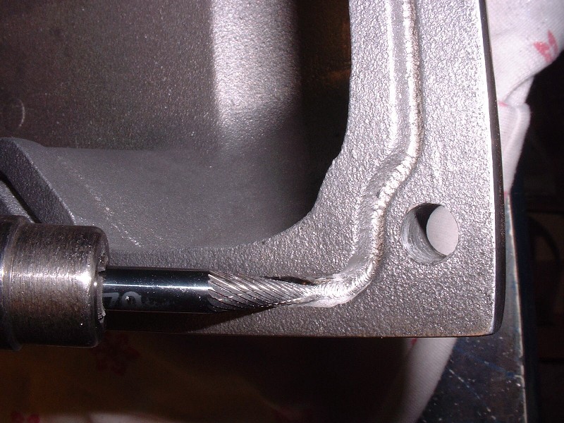
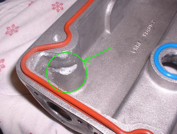
Problem #4 involved more casting issues. When I turned the cam covers upside down, I noticed that the groove for the cam cover gasket was cast and not machined into the parent material. This isn’t necessarily a problem in itself, but again, the casting wasn’t perfect. There was a fair bit of very granular casting flash in the bottoms of the gasket grooves which would have prevented me from installing the gaskets properly and would have caused leaks. Here’s a picture of what I’m talking about:
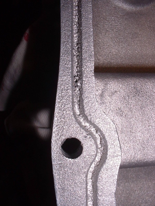
To correct this I had to take a die grinder with a special bit and carve out the excess aluminum from the grooves. Once again, for the average Joe without the right tools, this may have presented itself as a major hurdle. It was certainly a disappointment regardless of experience and skill.
Problem #5. On the Northstar engine one of the intake cams protrudes through the cam cover so that a small pulley can be attached to drive the water pump. In addition, there are supposed to be three tapped holes to be able to secure the seal that prevents oil from leaking around the cam where it sticks out of the cover. Neither the camshaft hole nor the seal mounting holes were bored. I returned to the website where I bought the covers and could not find where it was stated that these had to be machined by the buyer. Have a look at the stock cover:
And the cover as delivered (note that the marks for determing the location of the hole were made by me):
One final problem was that the cam cover, even once modified for the water pump drive shaft, would not fit on the engine. The covers are significantly heavier castings than the stock covers and the extra thickness around one of the cover’s mounting holes simply would not clear one of the camshaft bearing caps. This meant that I had to shave some material off the inside of the cam cover to get the necessary clearance. Not much… but enough that it could drive you crazy after all the other little issues to deal with.
Next post I’ll show you how I measured and made the holes in the right spots for the water pump drive shaft and oil seal.
|
|
|
|