
 
     |
| LS4 / F40 swap - fieroguru (Page 186/216) |

|
fieroguru
|
APR 02, 06:21 PM
|
|
The epoxy is done. I wanted a brighter blue, but the flakes I had kept the epoxy clear, which I didn't like. So I added in the grey tint from Langmuir and it made it more a slate grey. I am just glad to be done with that step so I can continue on with the assembly.
|
|
|
|
fieroguru
|
APR 09, 09:49 PM
|
|
The mill continues to take shape. It was under power today and I was jogging it around squaring up the X-axis, setting limit switches, and having it complete the homing cycle.
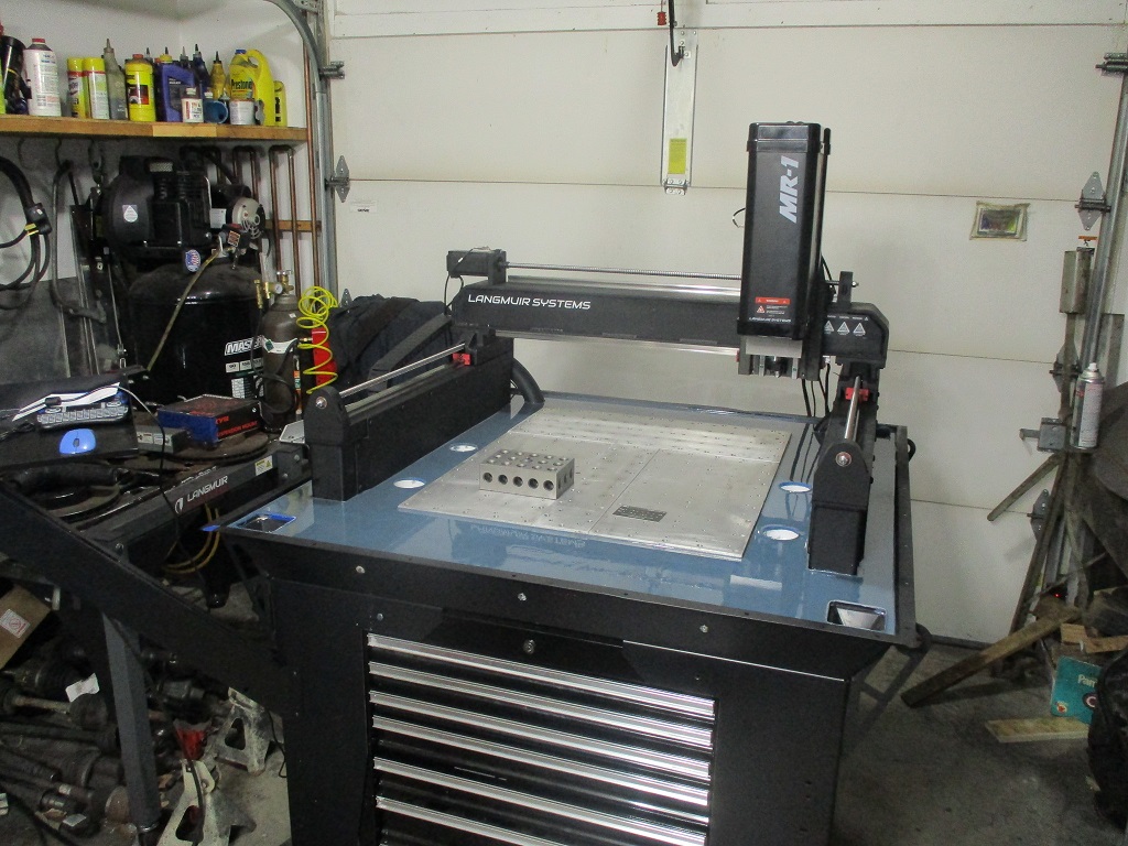
Still have several more modifications to complete before I start installing the enclosure.
|
|
|
|
fieroguru
|
APR 15, 06:54 PM
|
|
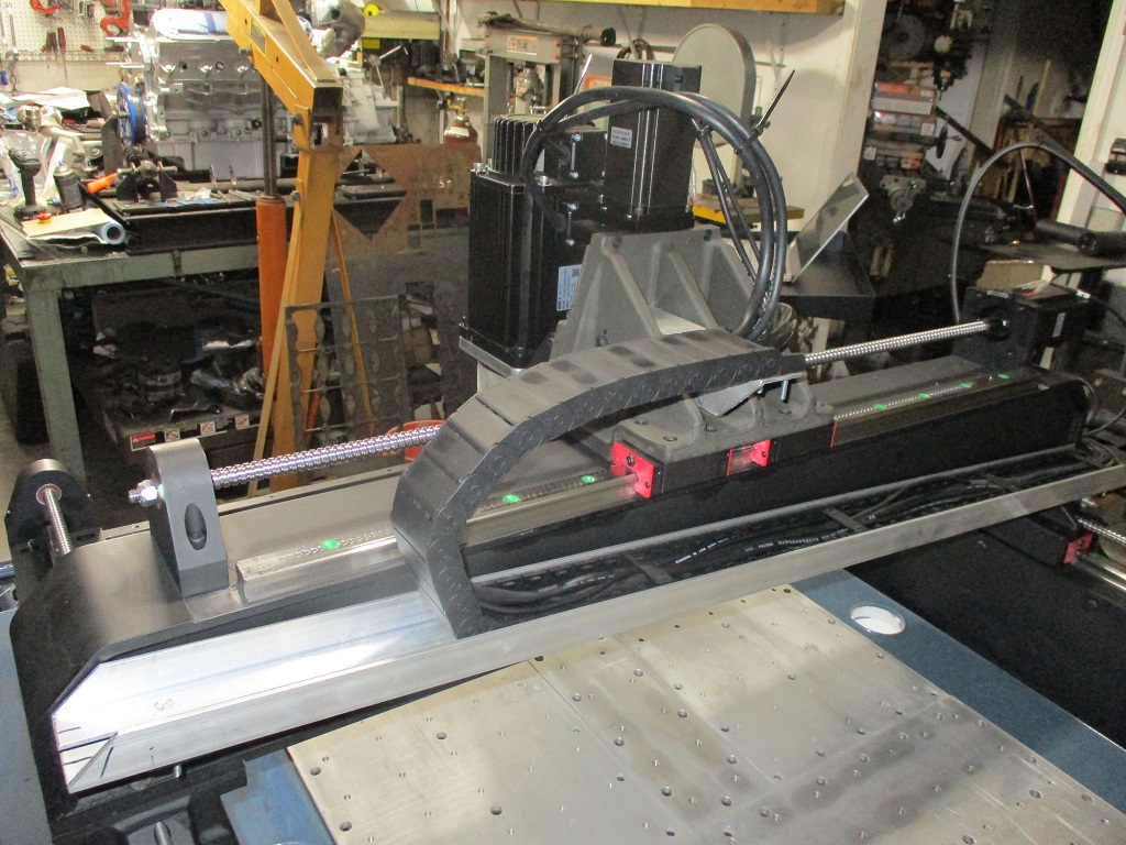
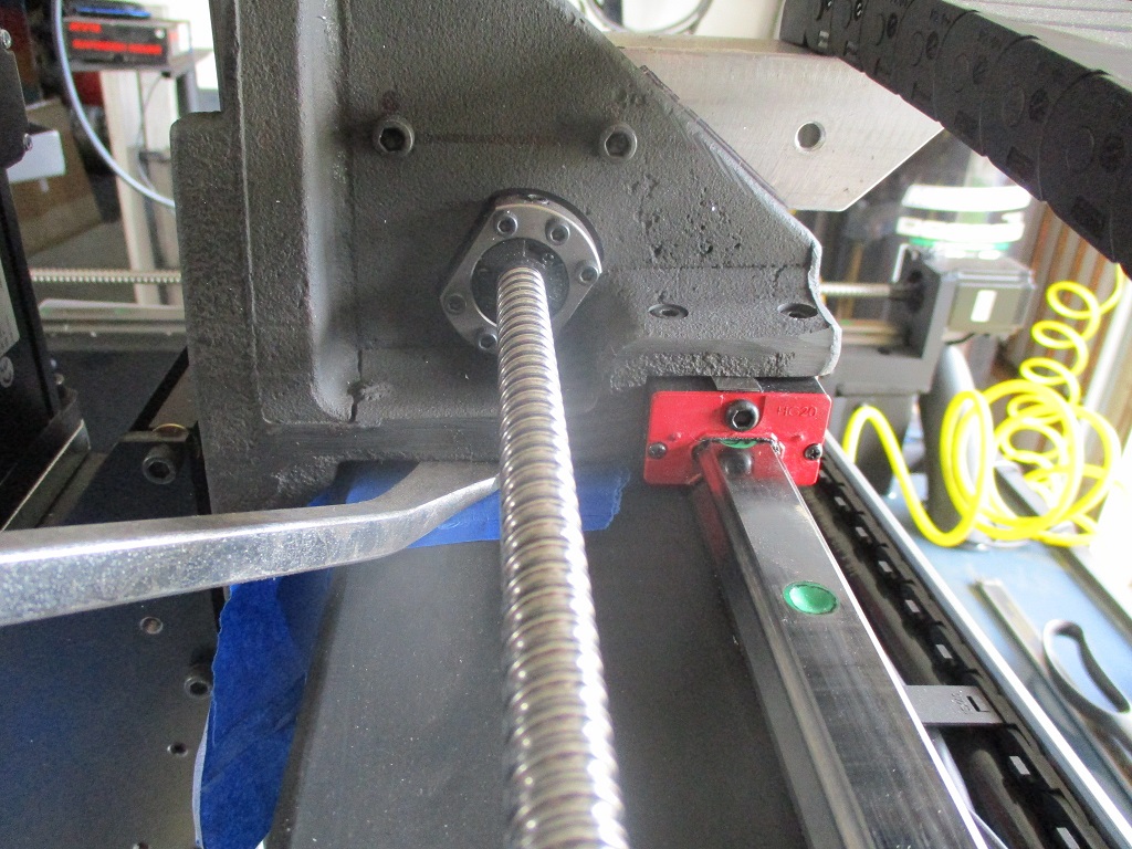
Finished with the fabrication of the cable control rails. I did end up extending the Z limit switch cable about 4’, but once that was done, everything else fits like it should. There is ample cable length to tuck the controller box up under the left hand side. All the cables are currently in place, but I left most of the covers off for fine tuning lengths at each motor/switch/device.
Here you can see the probe and flood coolant hose. Both are longer than they need to be:

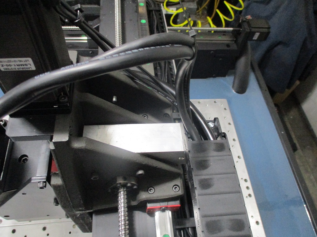
Here is the backside of the spindle:
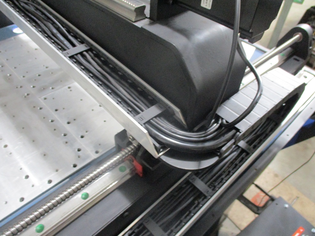
Here is the backside of the X-rail:
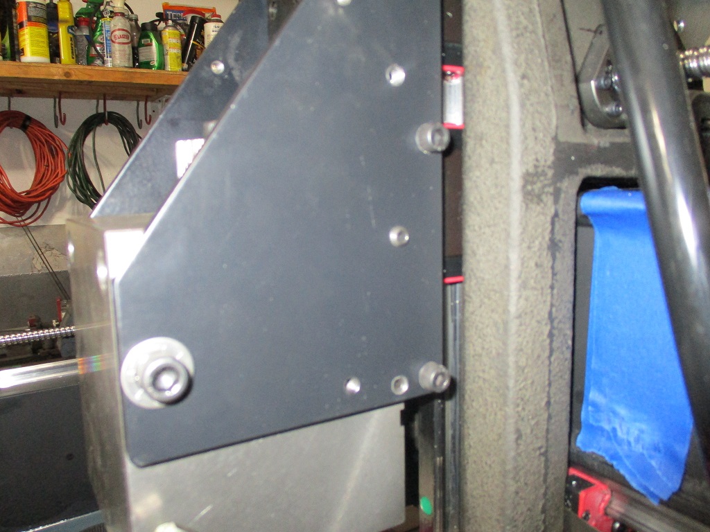
Here is the X to Y cable transition on the remade 3/16" plate:
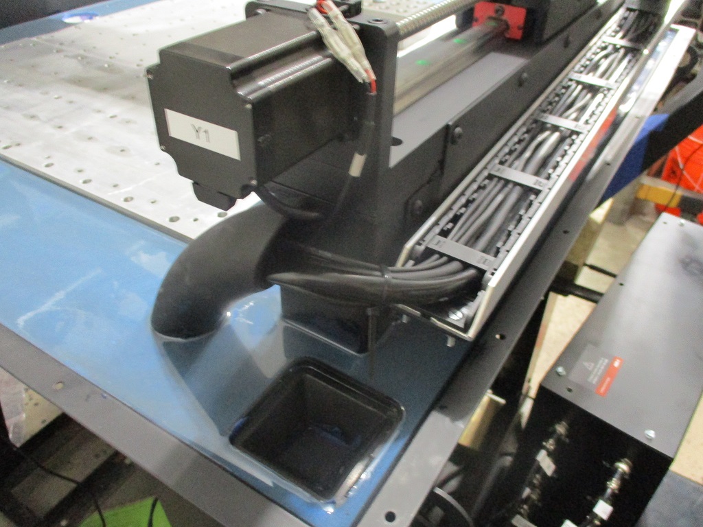
Here is the Y1 to conduit transition:
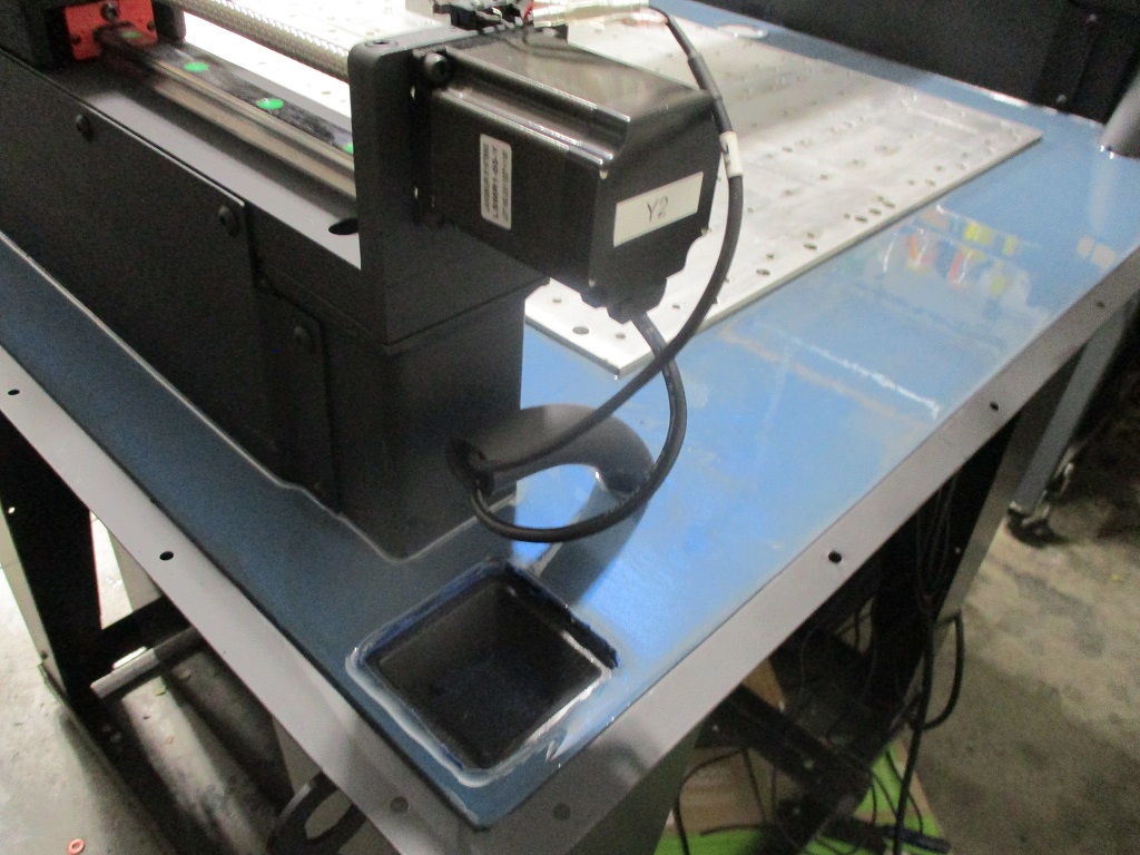
The Y2 to conduit transition:
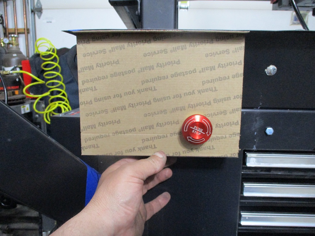
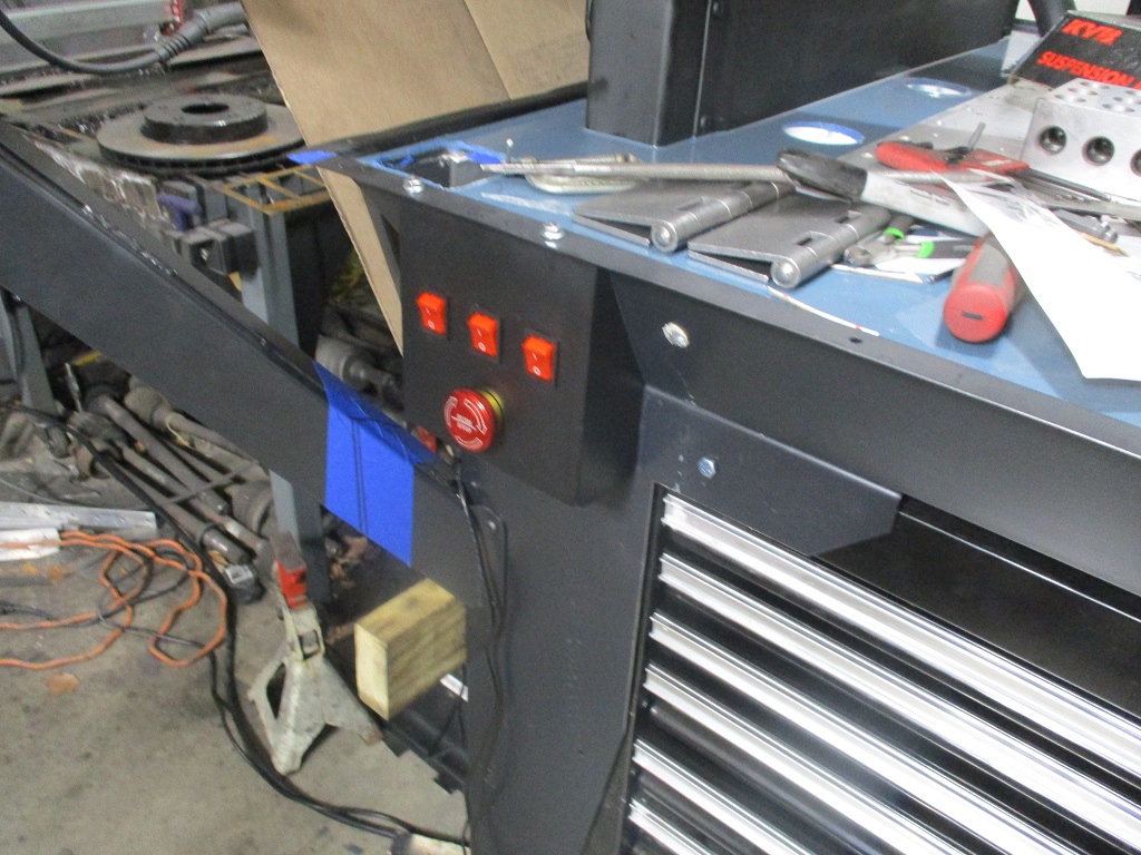
Here I am getting started with the relocate the E-stop, 120v switch and 240V switch to the front of the machine:
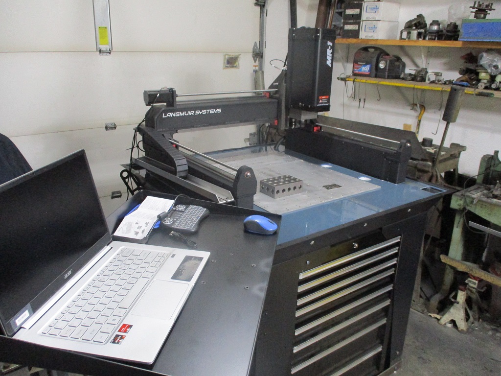
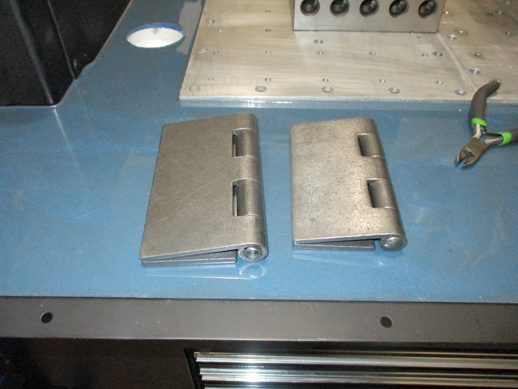
Here are the hinges for the computer stand. One to swing the arm out of the way, one to drop the laptop tray vertical.
|
|
|
|
fieroguru
|
APR 16, 06:49 PM
|
|
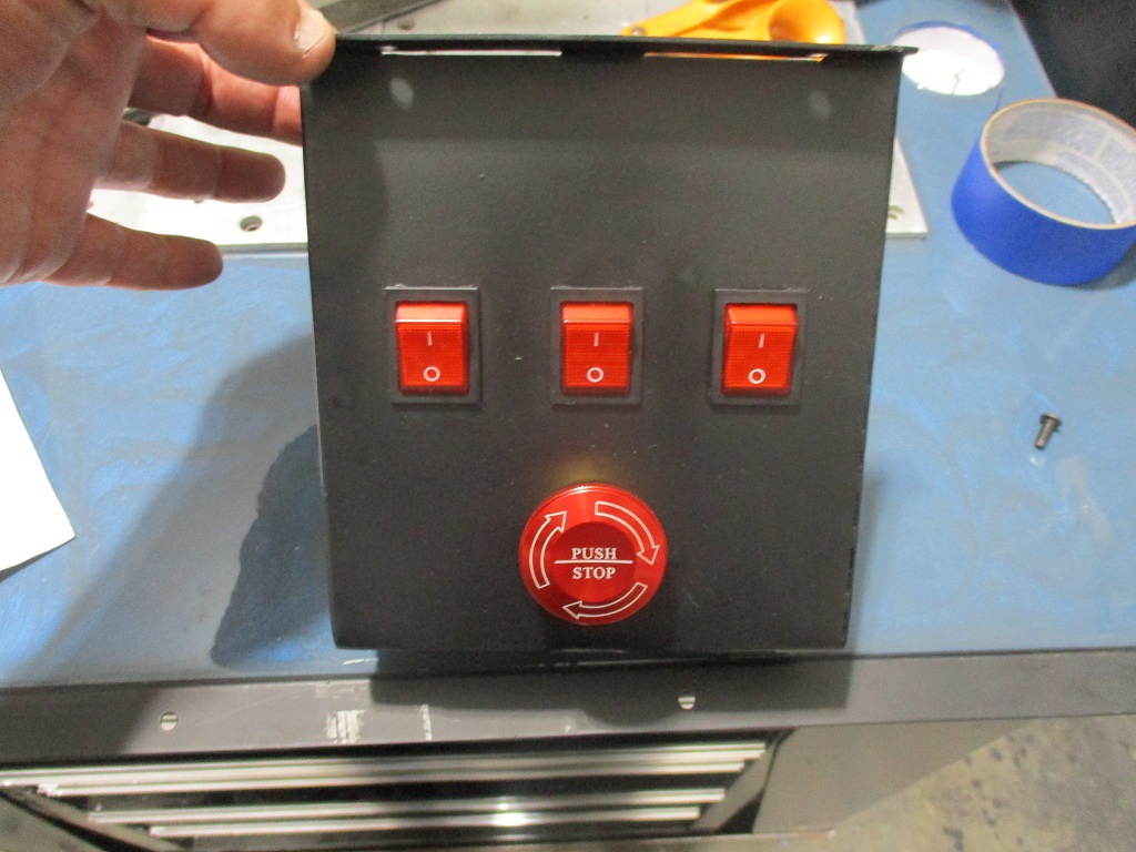
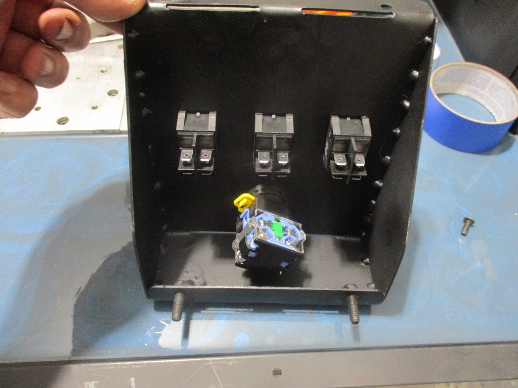
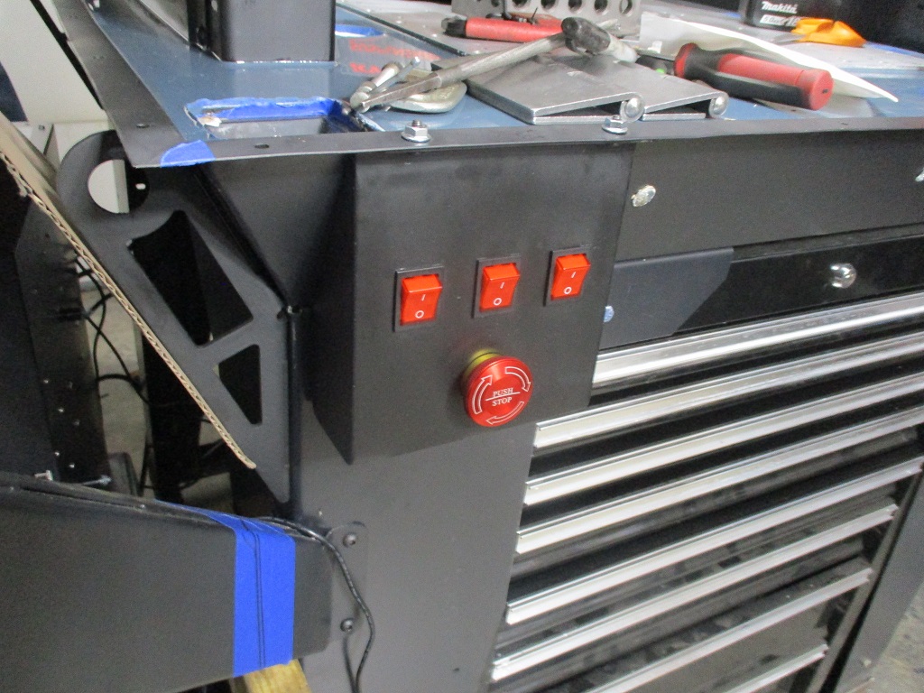
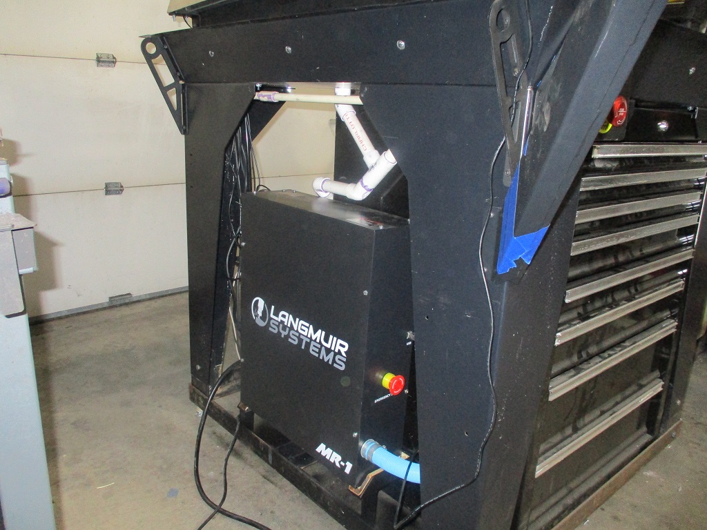
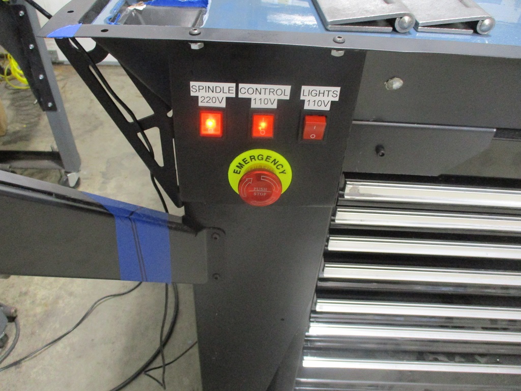
The fabrication of the auxiliary control box is done. It has the e-stop and switches for the 240V spindle, 120V control power, and 120V for the lights. The wires will pass through the leg into flexible conduit back to the control box.
|
|
|
|
fieroguru
|
APR 23, 06:50 PM
|
|
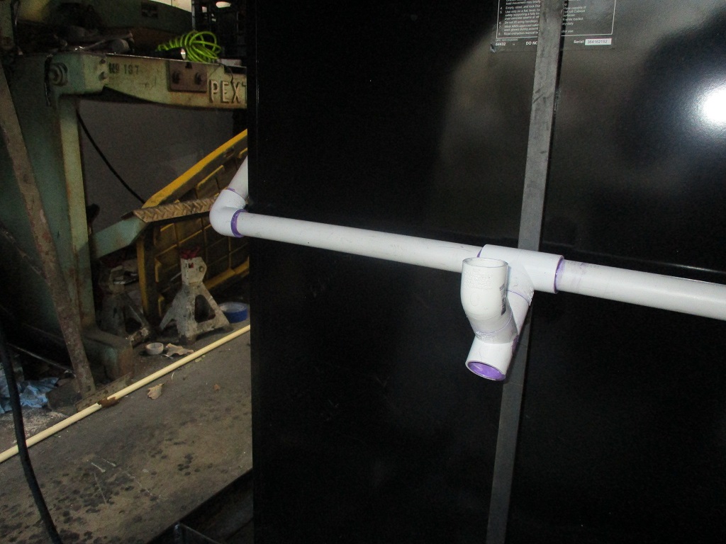
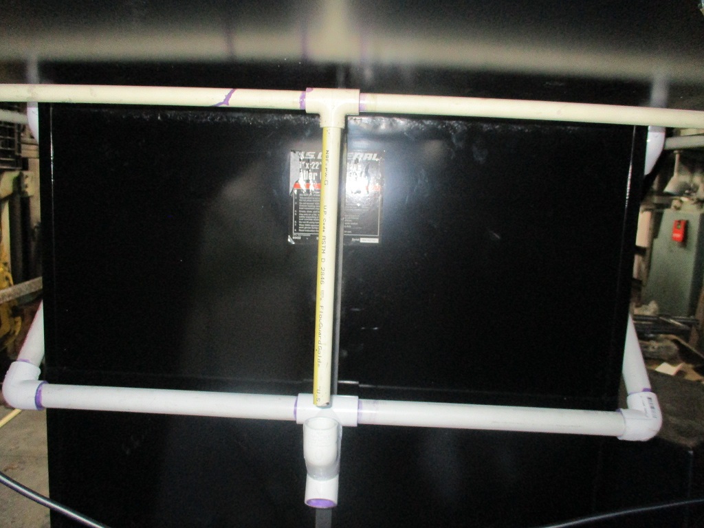
Last weekend I thought I had finished out the drain plumbing from all 8 drains to a single tube going back to the flood coolant tote.
This weekend I finished up the wiring for the relocated switches and e-stop. Made a new stand to mount the control panel, which required a slight modification to the drain path on the left side, and tested everything out. Also complete the spindle break in procedure.
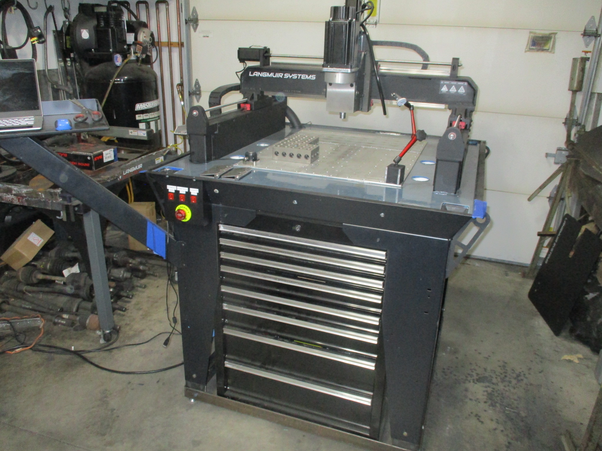
Sometime this week I will likely start surfacing the base plate so I can tram in the Z-axis.
|
|
|
|
fieroguru
|
APR 29, 08:29 PM
|
|
Made some chips fly today!
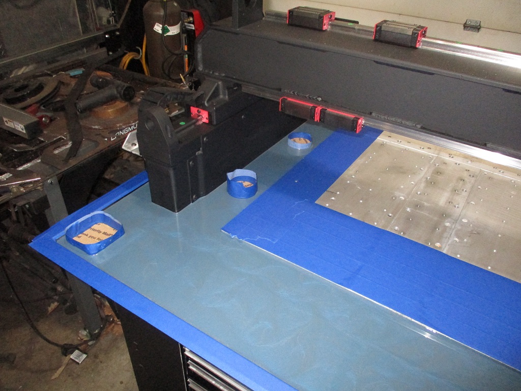
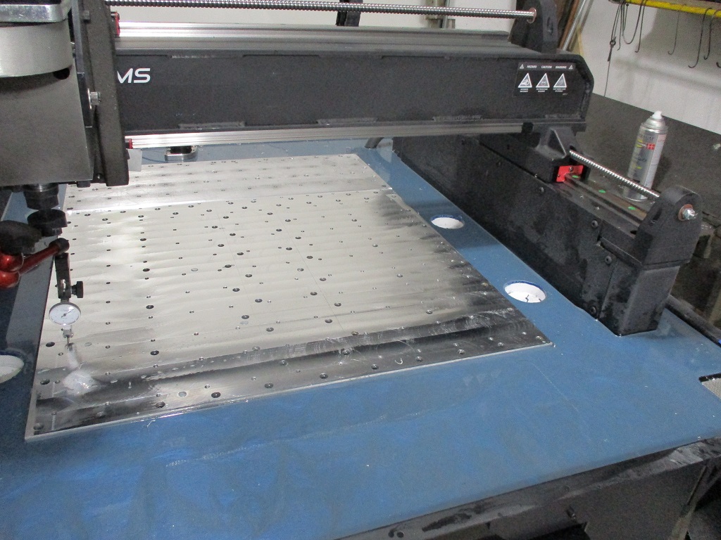
Started the first couple of passes on the thicker portions of the base plate. I use my 2.5" flycutter with the Langmuir bit holder and insert, set the rpm to 1500, feed to 15 IPM and used a 1" step over, and in manual mode.
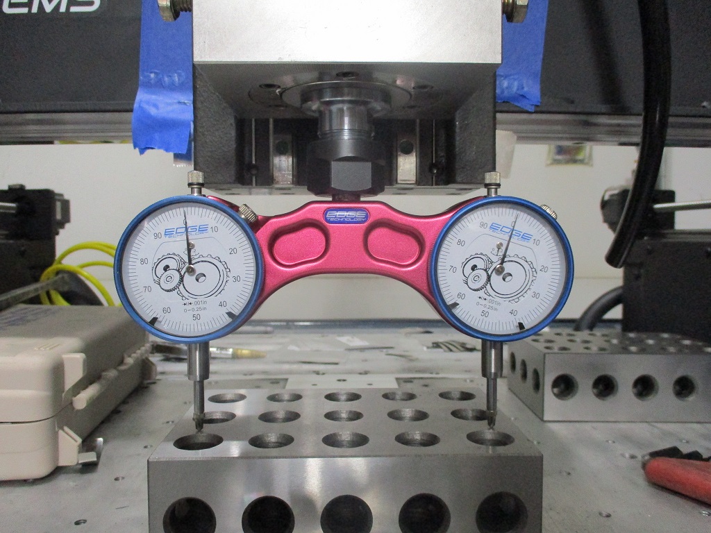
From there I stood one of my 2x4x6 blocks on end and ran the indicator down the side. This showed the Z out to the point I needed to add some shims to the top right (no shims installed during assembly).
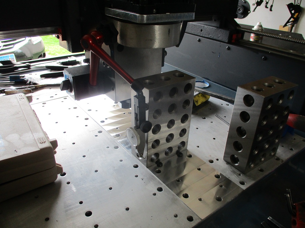
To install the shims, I loosed the 3 large horizontal bolts on the bottom, loosened up 6 of the 8 top bolts to the bearing block - leaving the two on the far left tight, put some tape on the gantry, then used my prybar to raise the right side to slide in the shim, rerun the indicator, add/remove shims, until it was within 0.0005" across 5.5". Then I pushed the spindle carriage to the rear and tightened up the loosened bolts.
Then I turned the 2x4x6 block 90 degrees and ran the indicator up and down the front. I needed to bring the bottom out and the long horizontal bolts were already loose, so I added more tape to the gantry face, pried the bottom out to added shims to the bearing/block face. Rerun the indicator, add/remove shims to get within 0.0005" over 5.5".
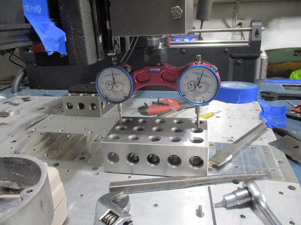
Then I put the 2x4x6 block on its back and pulled out my 5" tram tool and zero’d it. I took the side plates off and drilled and tapped three 1/4-20 holes on each side. The holes are 3/4" from the back of the plate. The two bottom ones are 1/4" from the bottom of the plate and 1/4" below the top of the spindle block. The top hole is 2" from the middle hole.
With the side set screws, I was able to loosen the two 1/2" bolts on the back, the front bolts through the plate, and use the 4 set screws to jack the spindle so it was level side to side (within 0.0005" over 5") after tightening all the bolts.
Then I spun the block and tram tool 90 degrees just to check… expecting it to be good to go (machined block, on machined plate…). But it was out too. The top of the spindle block needed to come away from the back. At that point, I decided to take off the motor and offset housing so I could have better access to the back of the block to install some shims. Some trial and error, but able to tighten everything back down and get within 0.0005" over 5".
Now of course when I installed the block shims to address the front/back spindle tram, it messed up my side to side tram, so I had to go back and do that again… but it was super easy to do the 2nd time.
On Sunday I am planning to surface the remainder of the front of the baseplate and check for any variations along the X and Y axis.
|
|
|
|
fieroguru
|
APR 30, 07:46 PM
|
|
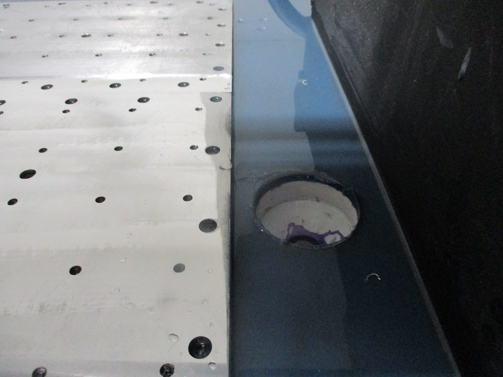
I am about 90% done surfacing the front of base plate. There are still 2 low spots in the front left and rear right.
This was a worn spot in the Langmuir plate and not all of this will clean up, but anything past the 1/4-20 mounting holes will not matter anyway.
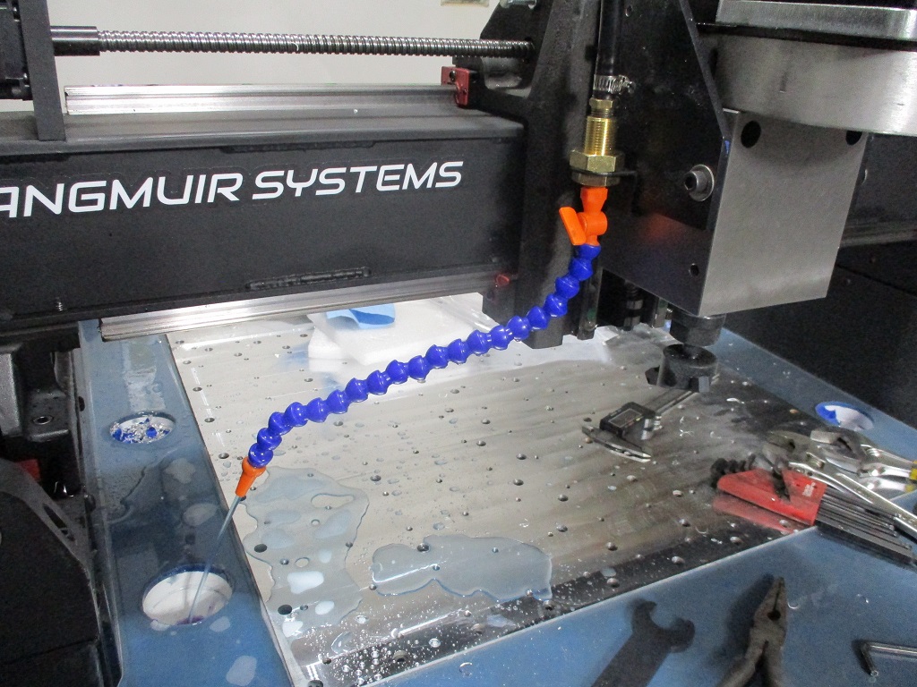
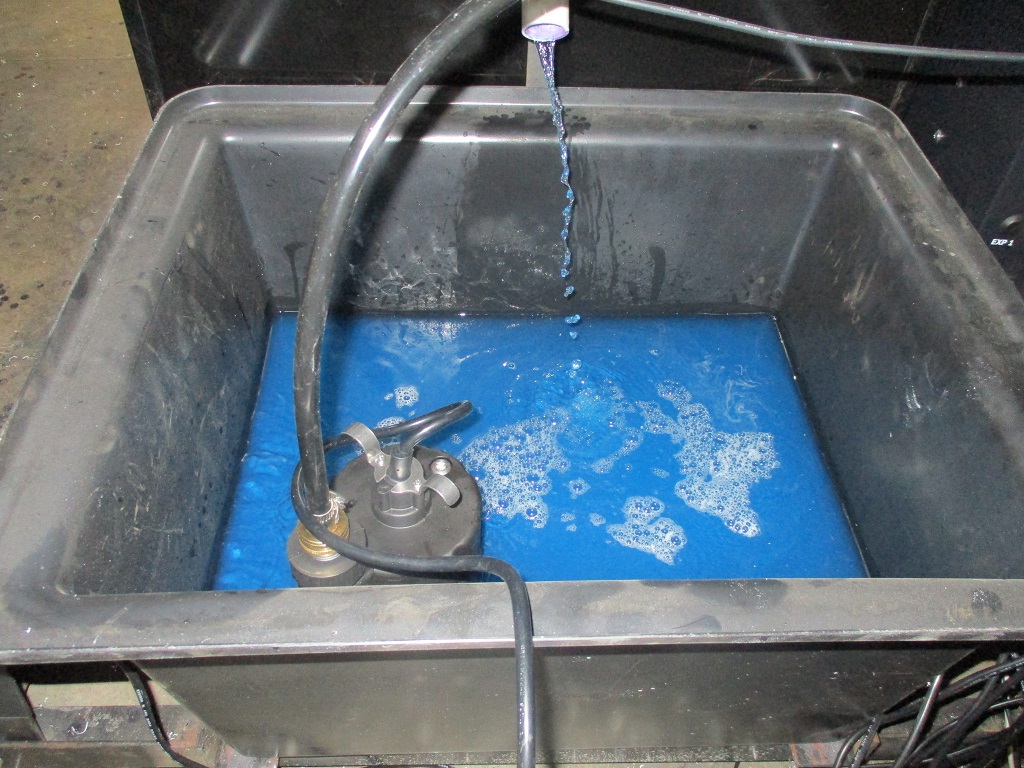
I wanted to have the flood coolant operational for the finish passes so I took some time today to get everything hooked up and mixed up about 5 gallons of the fusion coolant.
|
|

|
Fie Ro
|
MAY 02, 06:25 AM
|
|
I had to reread your previous posts to understand what you were doing and why but I see it now. That is some heavy and sturdy machine!
I know now it takes a lot of steps before you have a cnc'ed part in your hands. I recently finished my hobby cnc router that never worked when I got it 15 years ago. It is a less accurate and cheaper machine but the working principle is the same. Replaced all drivers, wiring and BOB, made a nice control box and got it tuned up in Mach3. It was quite a learning curve and a lot of things to sort out. Then there is the workflow from design to gcode and the actual part. My workflow for 3D printing didn't cut it (!) for the router so I started using Freecad and already made some parts. It is incredible how much time I spend to get this far. But it is priceless to have machines that can make parts without spending hours sanding and using handtools to get a part that is maybe right.
Good luck on making parts!
|
|
|
|
fieroguru
|
MAY 03, 06:51 AM
|
|
Yeah, my CNC plasma was a game changer for all my metal brackets and paid for itself in the first year. I can now use more creative and lighter designs and cut them out much, much faster. I am expecting the same from the CNC mill. It will open up the ability to machine many of my current parts I outsource as well as some new parts I have in development.
It has been a lot of work to assemble and modify the machine to maximize its capabilities, but it should be worth it in the long run.
|
|
|
|
fieroguru
|
MAY 07, 07:29 PM
|
|
Finished surfacing the front of the baseplate and flipped the X-axis 180 degrees to the spindle is on the rear. This will allow me to surface the rear base plate.
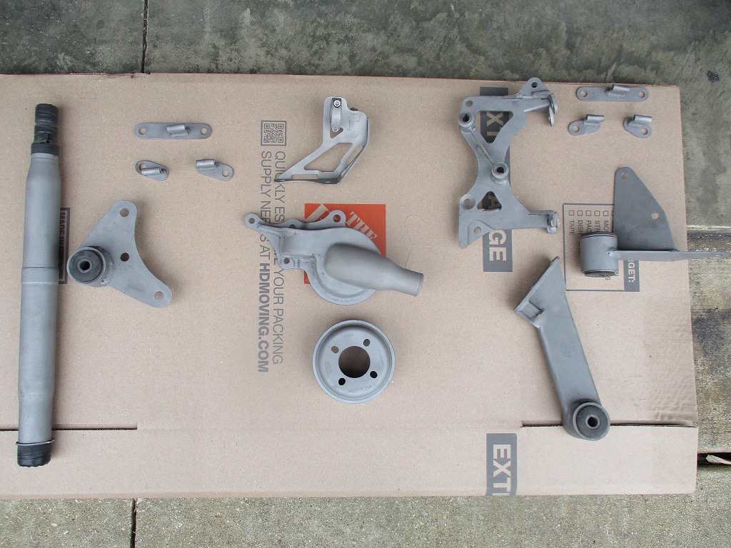
Also spent some time sand blasting the various brackets and parts I fabricated for the swap. Still have several more parts to sandblast and then it will be time to paint or powder coat.
|
|
|
|