
 
     |
| LS4 / F40 swap - fieroguru (Page 185/216) |

|
Trinten
|
MAR 03, 08:29 AM
|
|
| quote | Originally posted by fieroguru:
.... and it came out about 0.0013 off between the two 45" diagonal measurements w/o any shims. Looks like my time with the machinist level, the jack bolts and hold down brackets paid off. After the concrete pour I will be able to shim it to get even closer.
|
|
Some emphasis added by me in the quote. If you get that any closer to 0, NASA will be able to contract out small jobs to you! lol
I think you are already exceeding most tolerances for standard machining work? The few times I've been involved with white papers and contracts on machining (which, has been only 3 times that I can think of, so limited experience), the tolerances were listed as 0.002.
As always man, impressive stuff.
|
|
|
|
fieroguru
|
MAR 04, 03:21 PM
|
|
| quote | Originally posted by Trinten:
Some emphasis added by me in the quote. If you get that any closer to 0, NASA will be able to contract out small jobs to you! lol
I think you are already exceeding most tolerances for standard machining work? The few times I've been involved with white papers and contracts on machining (which, has been only 3 times that I can think of, so limited experience), the tolerances were listed as 0.002.
As always man, impressive stuff. |
|
Thanks! Langmuir suggests the for the rails to be within 0.010" before pouring the concrete and then once cured shim to less than 0.005". I am not a fan of lots of shims, so I wanted to get it as close as possible before concrete. Just like my Fiero swaps, I am putting my own spin on the assembly to make it my own.
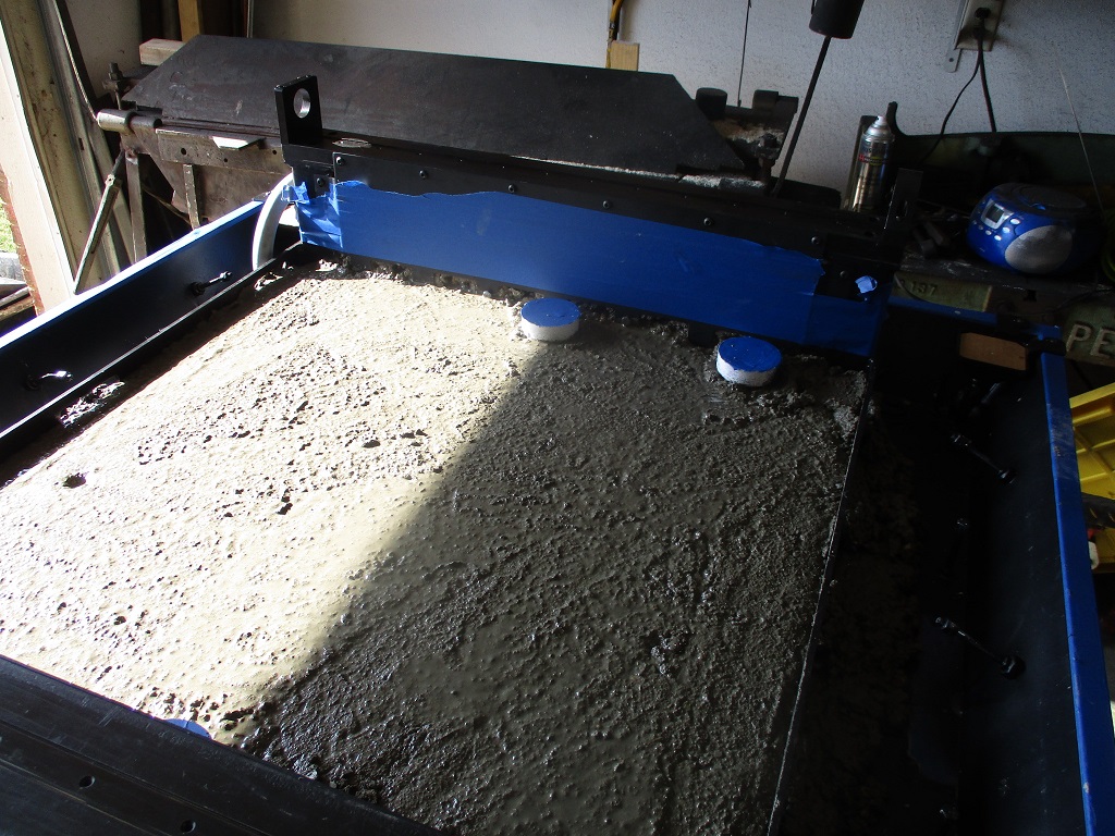
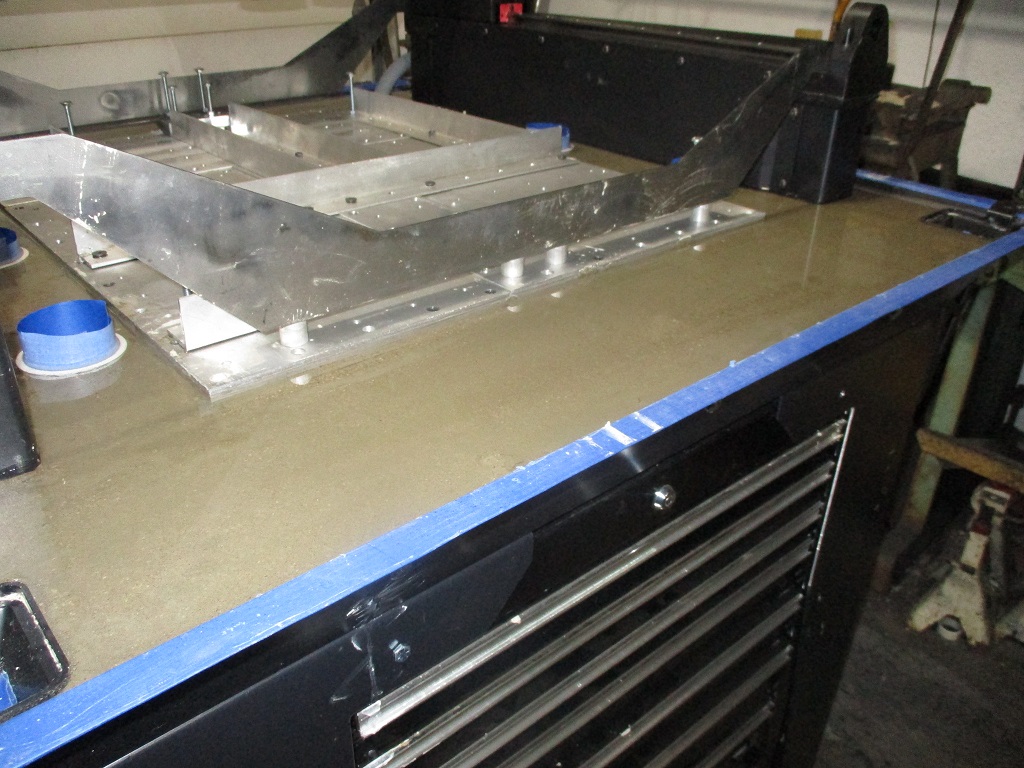
Concrete is done! Used 80 lb bags and mixed 2 at a time in a rental mixer. Used a 5 gallon bucket to transfer the concrete to the tray. My modified concrete pour sequence worked like a charm and the baseplate went in without much fuss.
Filling the Y-rail cavities (this is a modification unique to my install):
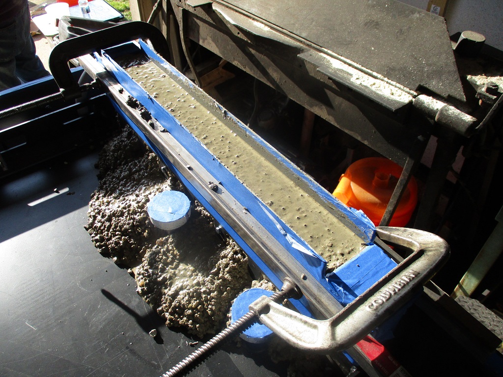
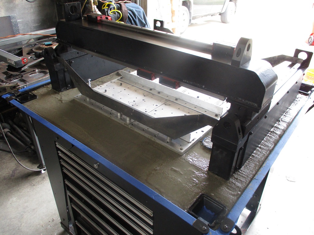
Removed the tape, installed the top rails, and bolted the side plates to the top rail. Then squared the assembly and tightened all the bolts.
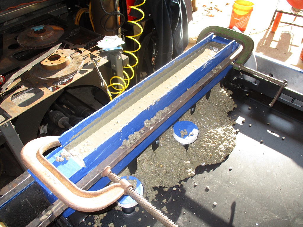
Then started filling just the center section of the pan:
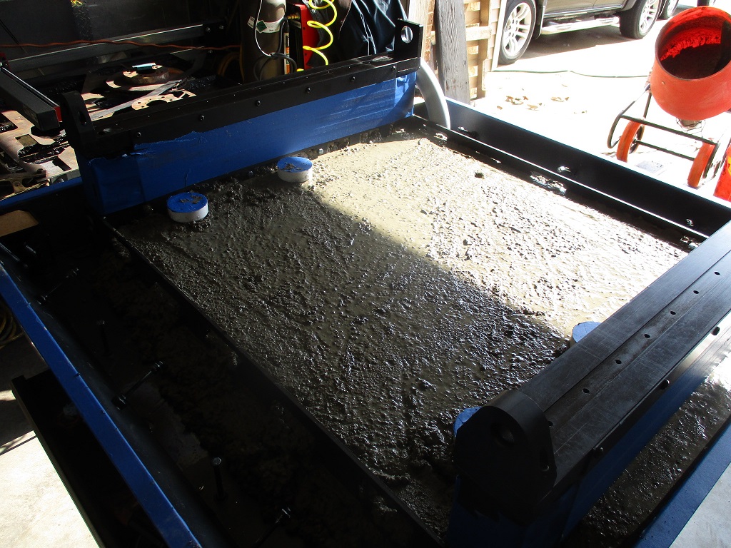
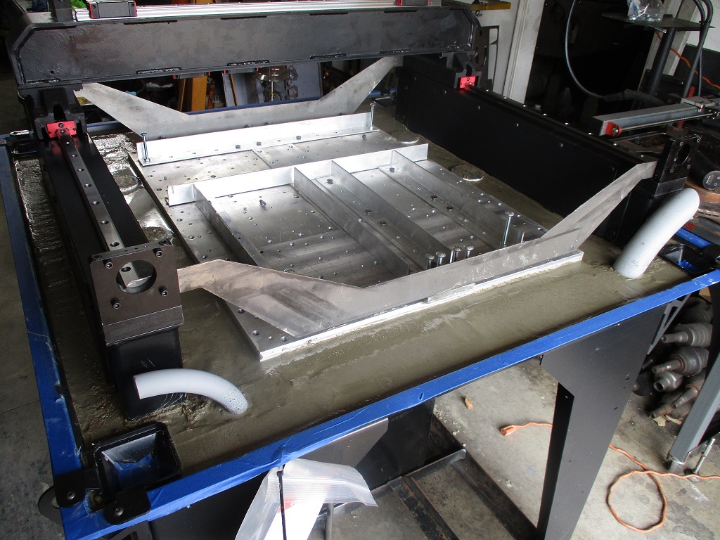
Added another couple of buckets of concrete and installed the base plate and positioned it tight to the right side of the left rail. Then filled in the outer perimeter of the pan, leveled everything off and started to remove all the tape and wipe things down. Once everything was clean, then the linear Y-rails and the X-bridge were installed so I could make the Y-rails parallel.
I am going to let everything cure until the morning and then I will add more water for a pond cure for at least 14 days.
|
|
|
|
fieroguru
|
MAR 05, 05:15 PM
|
|
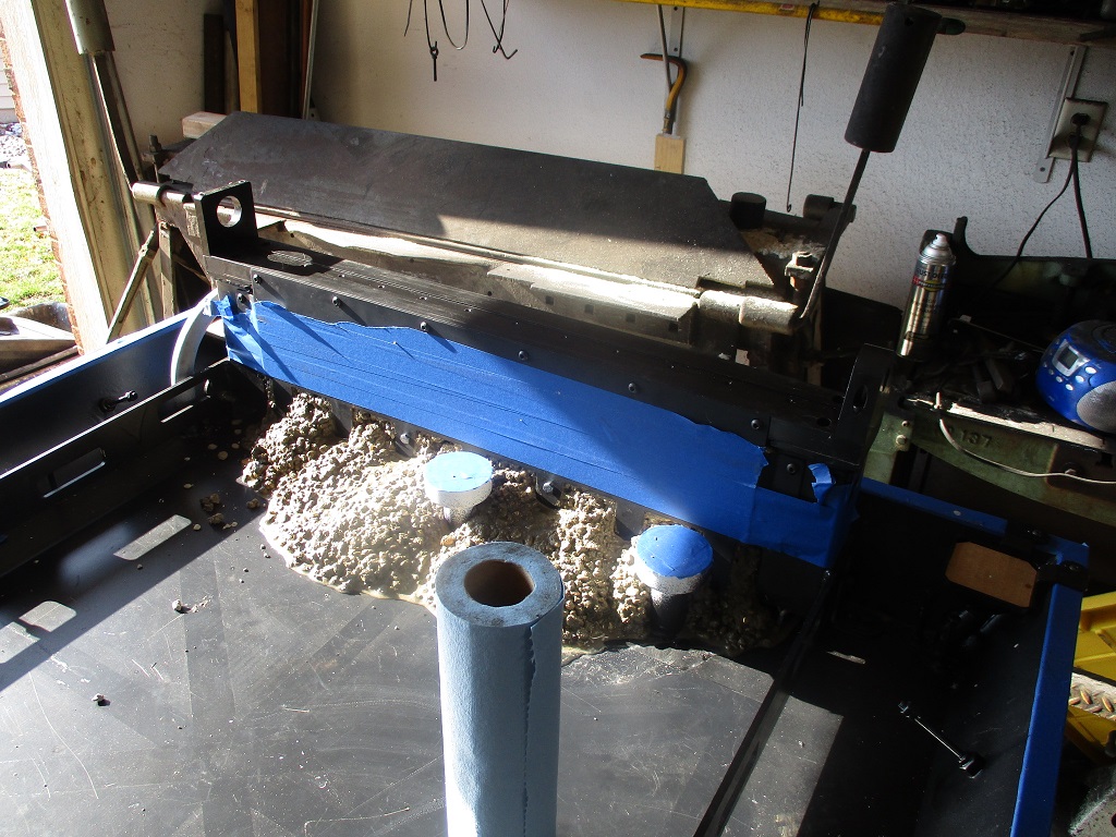
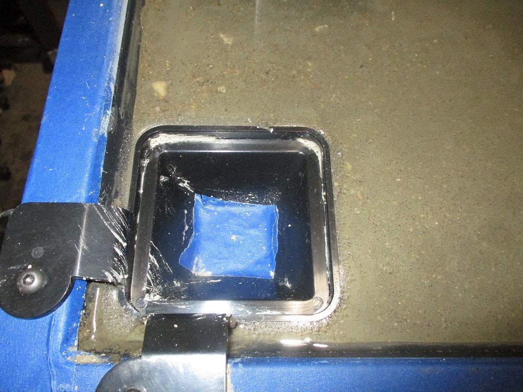
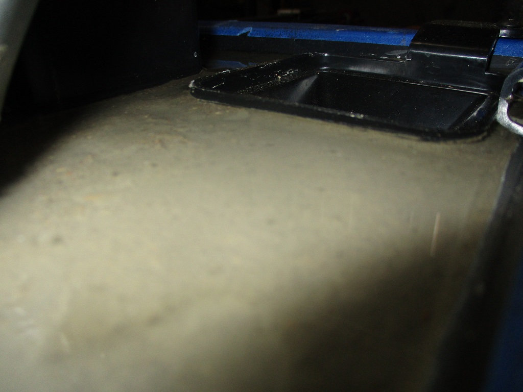
Started the pond cure this morning. Took about 1.25 gallons, so I will need to get a little more epoxy while I wait. 3 of the 4 corner drains are almost perfectly flat and level with each other, The one in the left rear seems to have popped up about 1/16". I think I will trim the sides of this one down prior to the epoxy. The new center drains are about 1/8" lower than the corner ones, so I will use tape like shown to create an edge dam for the epoxy on all the drains.
Now that I am in a holding pattern for the mill, I started to do some more work on the Fiero.
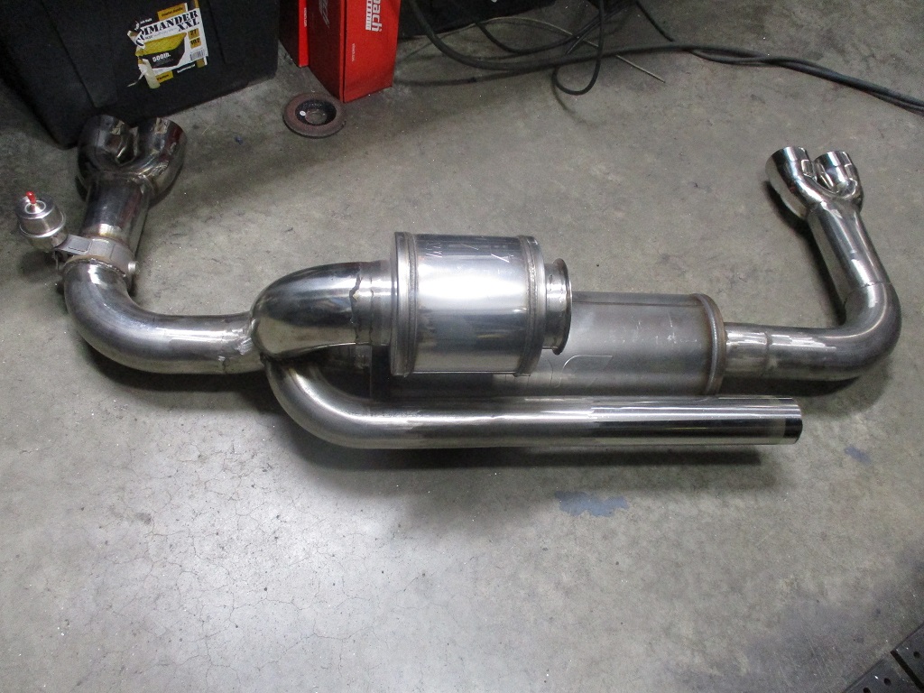
Today I completed all the finish welding on the cold side and the exhaust. I also swapped out the vacuum activated cutout with one that is boost activated.
|
|
|
|
zkhennings
|
MAR 07, 05:18 PM
|
|
|
That's a lot of work, looking good!
|
|
|
|
fieroguru
|
MAR 19, 07:16 PM
|
|
I spent the last week on vacation out in AZ and spent a couple of days in Phoenix, Sedona, and the Grand Canyon.
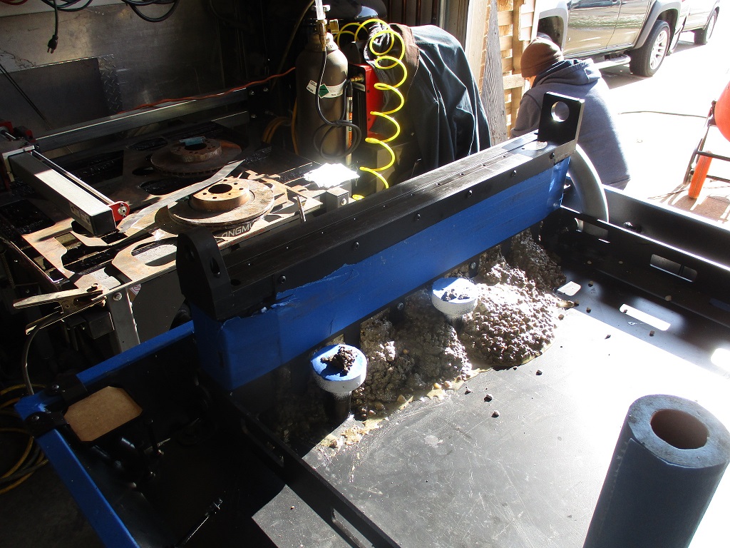
The concrete base for the mill is still pond curing the concrete (14 days in), but I was able to start removing the support brackets between the baseplate and removed the brackets from the corner drains - they just snap off. I will give it another couple of days and drain it. This coming weekend I plan to do the do the epoxy coat.
I was also able to finish up the resonator tube for the exhaust.
 [This message has been edited by fieroguru (edited 03-19-2023).]
|
|
|
|
dskebo
|
MAR 20, 01:00 PM
|
|
|
The mass airflow meter is on the wrong side of the turbo. It needs to be on the intake side after the filter before the turbo and it also needs to be in a smaller tube about 3" so it can read the actual flow of incoming air, Not pressure! I don't think you will be able to get it to even start where you have it and if it did the boost would break it and send shrapnel directly into the intake.
|
|
|
|
fieroguru
|
MAR 21, 07:35 PM
|
|
| quote | Originally posted by dskebo:
The mass airflow meter is on the wrong side of the turbo. It needs to be on the intake side after the filter before the turbo and it also needs to be in a smaller tube about 3" so it can read the actual flow of incoming air, Not pressure! I don't think you will be able to get it to even start where you have it and if it did the boost would break it and send shrapnel directly into the intake. |
|
Please do more research.
|
|
|
|
dskebo
|
MAR 21, 07:39 PM
|
|
|
|
|
fieroguru
|
MAR 26, 05:17 PM
|
|
Nothing really picture worthy...
Drained the water from the pond cure on the concrete for the mill base.
Roughed up the surface for the epoxy coat.
Checked the Y-rail co-planarity and got it within 0.001 across over 40+ in using Langmuir's tool and verified it with my machinist level.
Gave the Y-rails and cable tube a fresh coat of paint.
Next weekend I should be able to pour the epoxy top coat.
|
|
|
|
fieroguru
|
APR 01, 04:53 PM
|
|
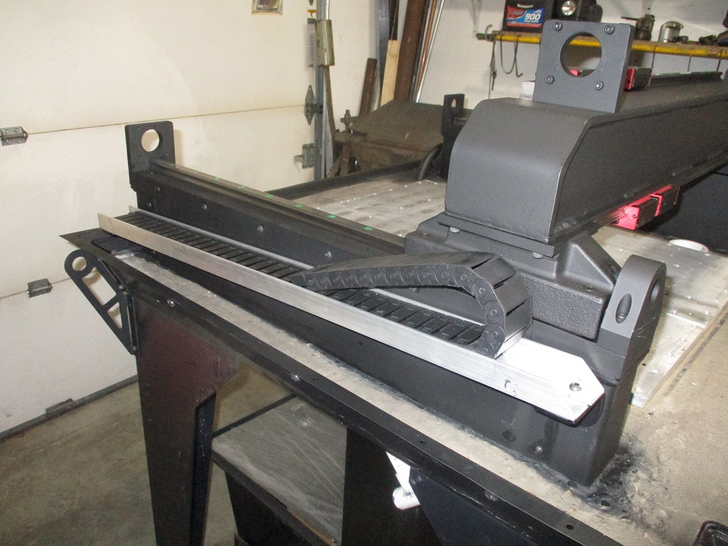
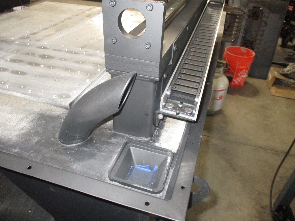
Tomorrow is the epoxy...
Today I did some more touch up painting and installed a flexible cable tray for the Y-axis. There will be another one similar to this for the cables running down the X/Z axes.

|
|
|
|