|
| LS4 / F40 swap - fieroguru (Page 184/216) |

|
fieroguru
|
JAN 03, 06:59 AM
|
|
|
Rebuilding and retrofitting my manual mill to CNC would have been too much of a project and the enclosure for flood coolant would have been very, very large. It basically came down to me wanting a newer more compact CNC unit.
|
|
|
|
zkhennings
|
JAN 03, 11:41 AM
|
|
|
That CNC looks sweet, is it able to recycle the coolant? Do you have to clean the chips out manually? I miss the days of being able to use the HAAS CNC mills at WPI.
|
|
|
|
fieroguru
|
JAN 03, 08:15 PM
|
|
| quote | Originally posted by zkhennings:
That CNC looks sweet, is it able to recycle the coolant? Do you have to clean the chips out manually? I miss the days of being able to use the HAAS CNC mills at WPI. |
|
Yes, there are drains in all 4 corners to drain the coolant back to the sump so it can be used again. Chip removal will be a manual process
|
|
|
|
ericjon262
|
JAN 03, 08:53 PM
|
|
| quote | Originally posted by fieroguru:
Rebuilding and retrofitting my manual mill to CNC would have been too much of a project and the enclosure for flood coolant would have been very, very large. It basically came down to me wanting a newer more compact CNC unit. |
|
I guess I was just thinking about the CNC Bridgeport style vertical mills I sometimes run at work, they don't have an enclosure. I can definitely understand wanting newer, better equipment, and wanting an enclosed unit, especially with minimal available space. ------------------
"I am not what you so glibly call to be a civilized man. I have broken with society for reasons which I alone am able to appreciate. I am therefore not subject to it's stupid laws, and I ask you to never allude to them in my presence again."
I invited Lou Dias to trash me in my own thread, he refused. sorry. if he trashes your thread going after me. I tried.
|
|
|
|
fieroguru
|
JAN 15, 07:41 PM
|
|
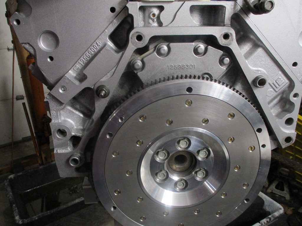
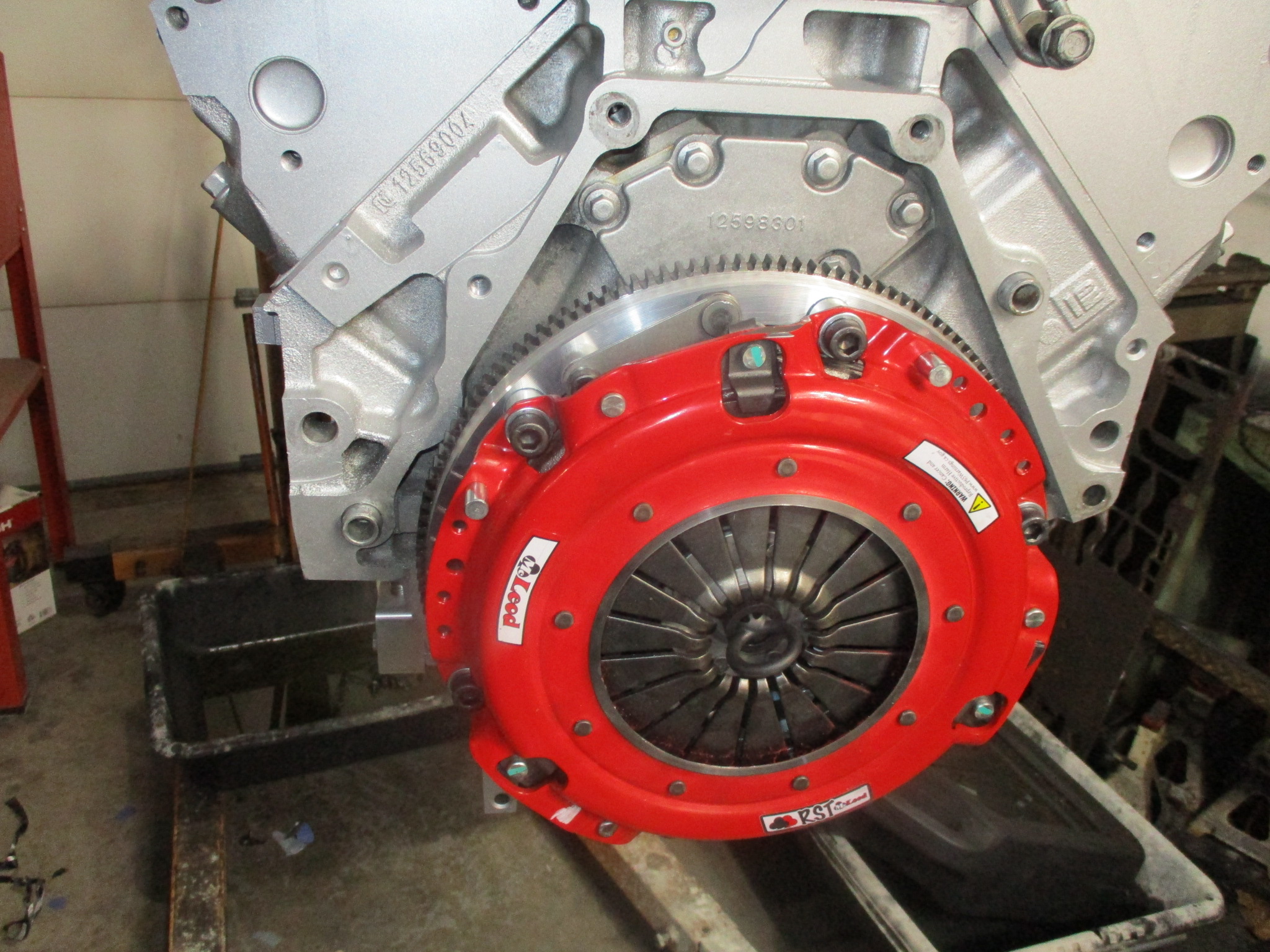
Spent the last few weeks cleaning and painting the engine and transmission, but it was time to get the engine/transmissions back together and back on the work table.
I installed the flywheel and clutch for the last time, applied Loctite and torqued all the bolts.
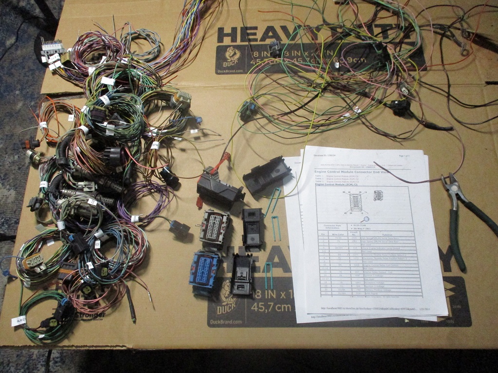
Also started the process of de-pinning the E40 ecm connectors (Sara is already asking how much longer this will be in the living room!)...
The MR1 mill arrives tomorrow, so assembling it (and modifying it) will be the major work for the next several weeks.
I am going to enlarge the baseplate area (so there is room to add a 4th axis), raise & reinforce the X & Y rails up to 2" (so the vices and clamps don't use part of the milling window), extend the legs a few inches, incorporate a tool box to the bottom for all mill tooling and stuff, and some lifting points on the sides. It is going to be a fun project!
|
|
|
|
fieroguru
|
JAN 28, 08:45 PM
|
|
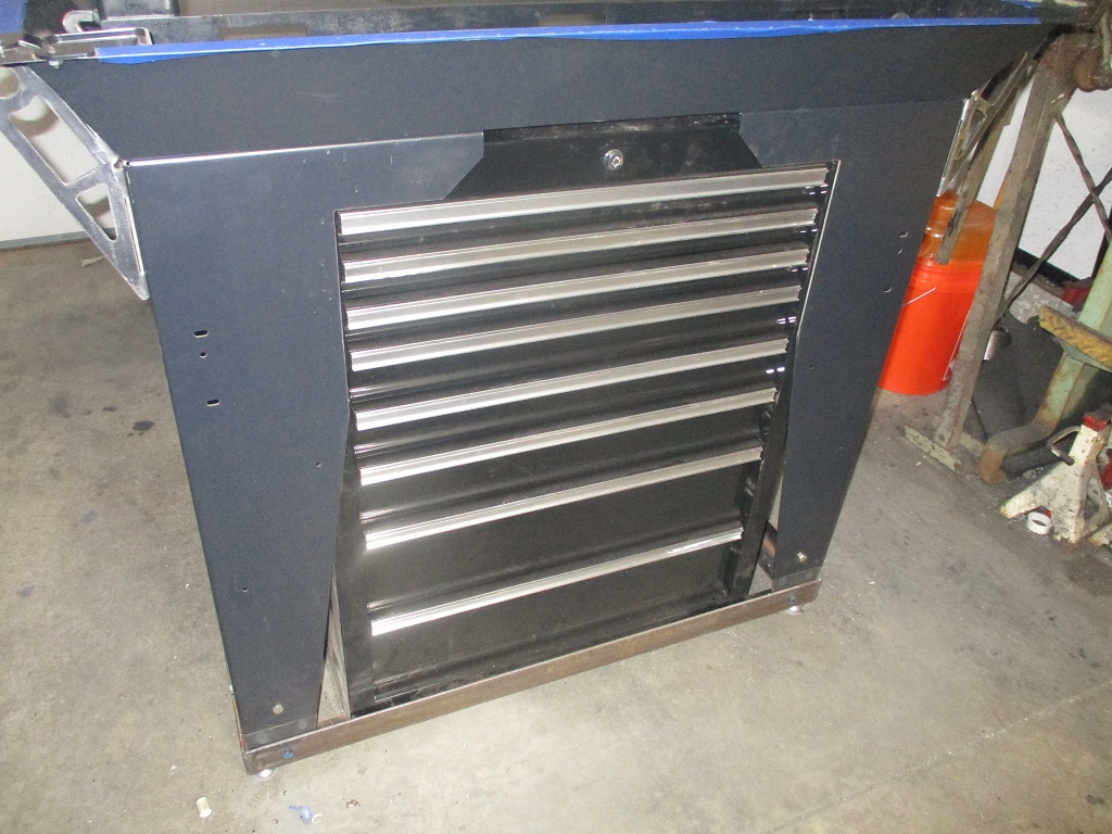
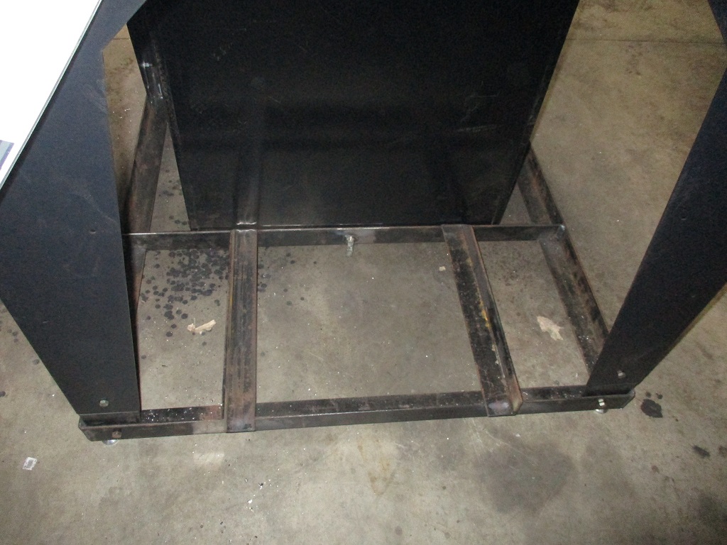
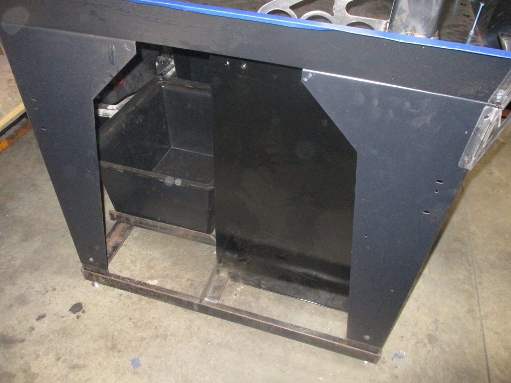
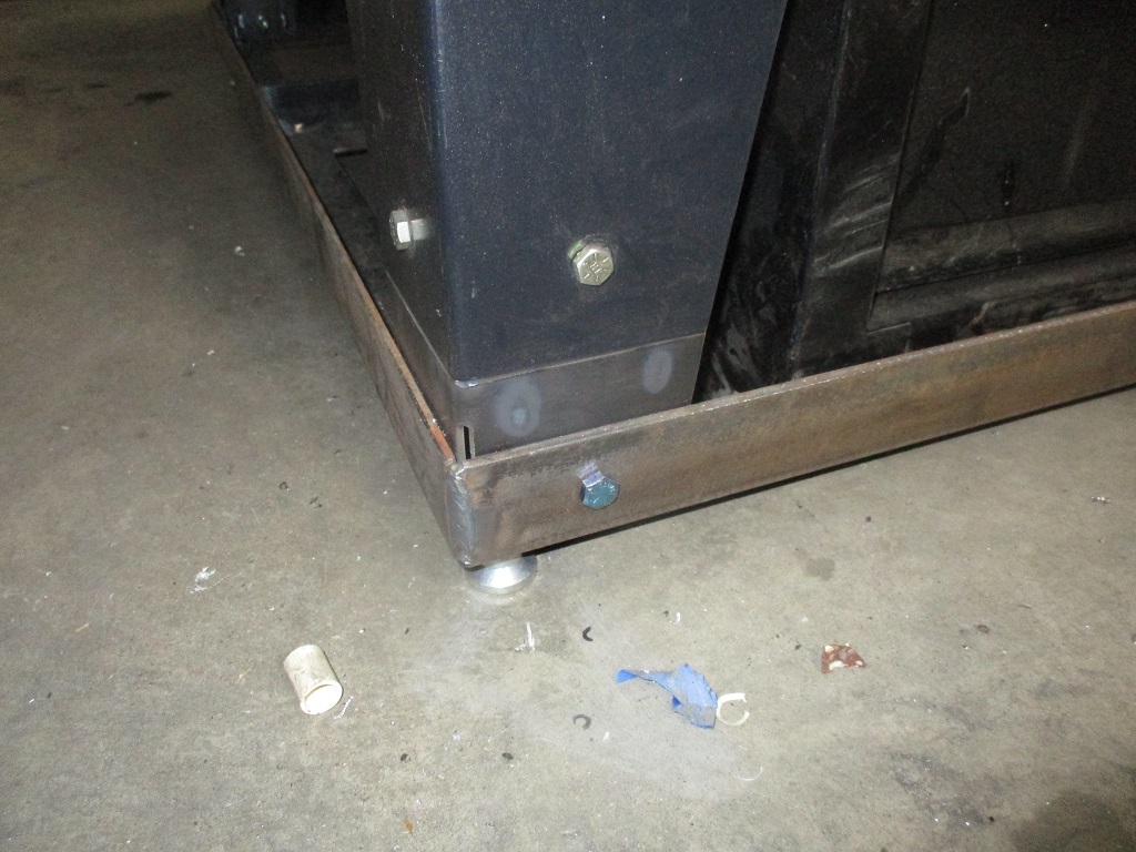
Started assembling and modifying the mill.
Added tool box
Made brackets to extend legs
Made 2x2x3/16 angle base for the legs, tool box and coolant flood tank
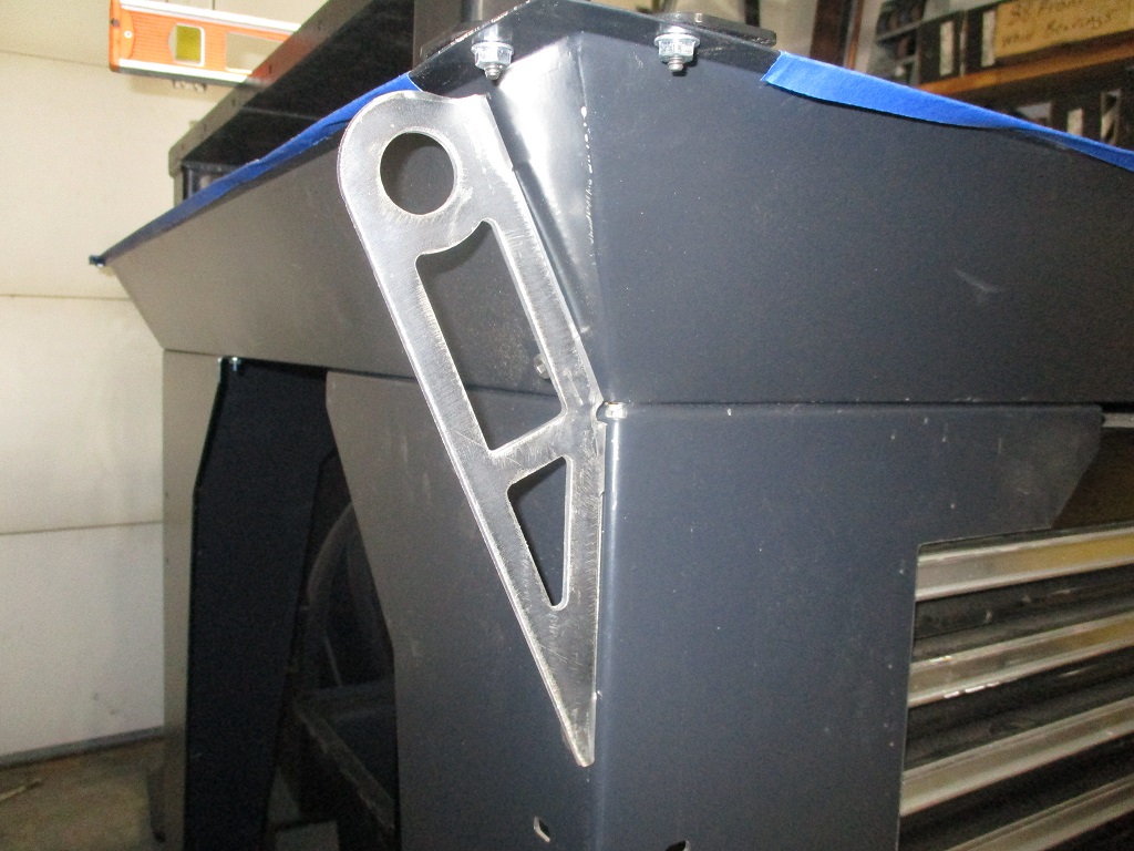
Made lift brackets for the 4 corners
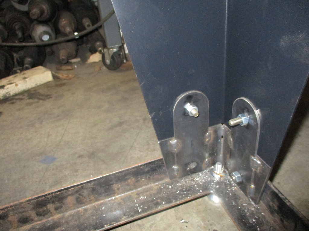
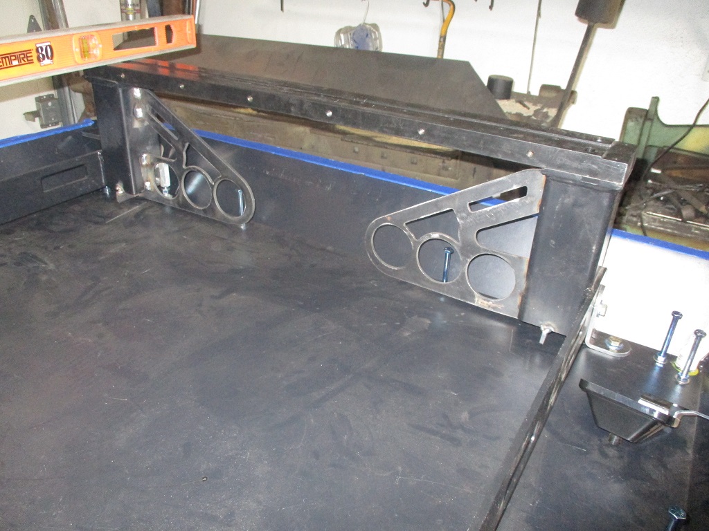
Started raising the Y-rails - added jack bolts to level, brackets to hold the rails in place, and gussets to engage more of the concrete.
|
|
|
|
fieroguru
|
FEB 08, 07:12 PM
|
|
Making progress on the mill.
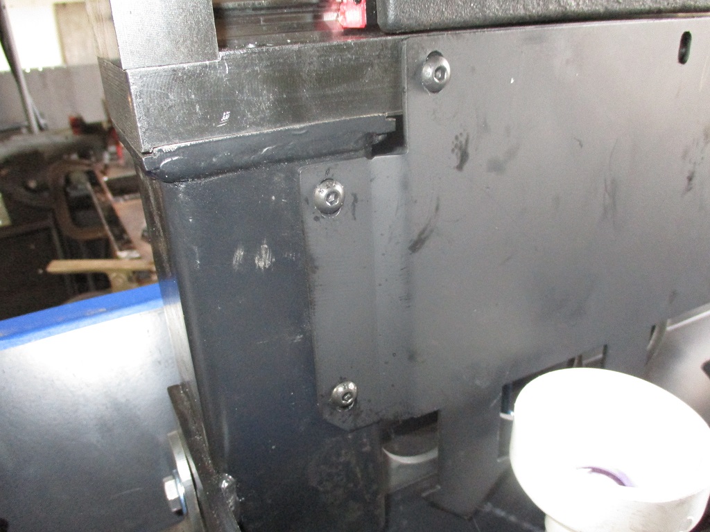
The y-rail side plates are now too short to seal at the bottom, so a new one was made that was 3/4" taller. It is also wider so the sides can be offset and bolt to the verticals of the Y rails. Bolting these side rails to the verticals is key to sealing the space under the y-rails as well as holding the verticals in position during the pour with the top of the Y-rails removed.
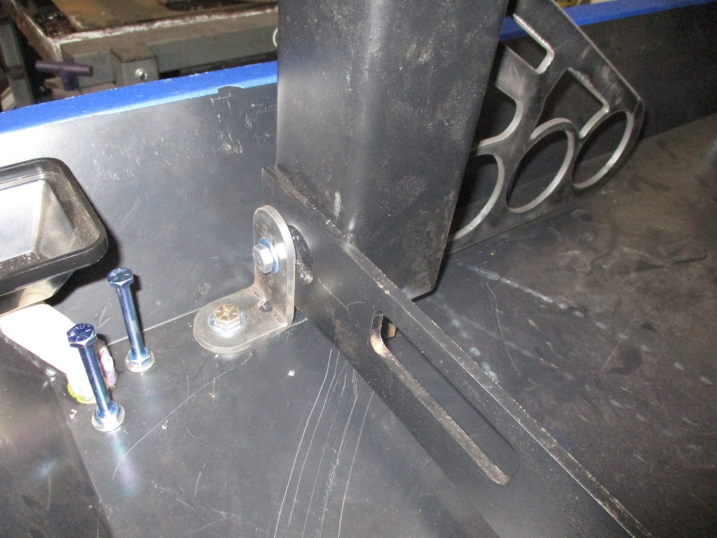
My machinist level came in so, I spent some time releveling the pan, then the Y-rails, and then added some brackets to hold the rails after I squared them up (picture of bracket a little later). I still need to double check co-planarity with the Langmuir tool, but suspect it will be close.
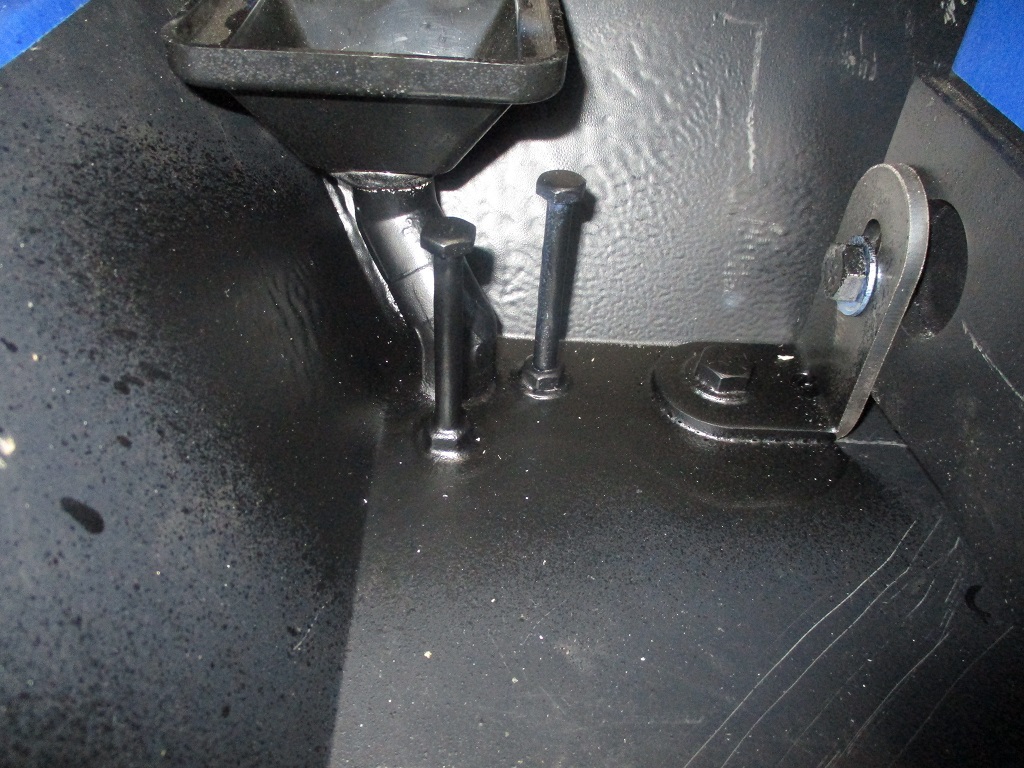
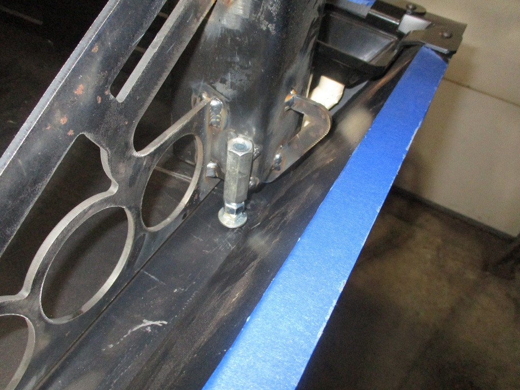
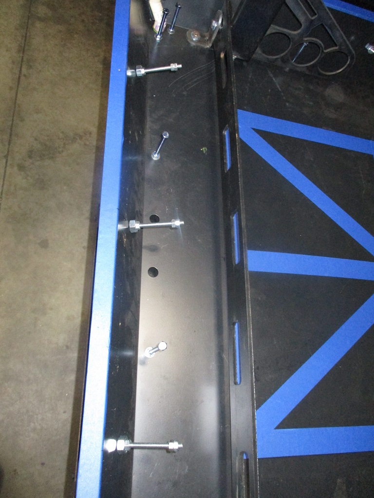
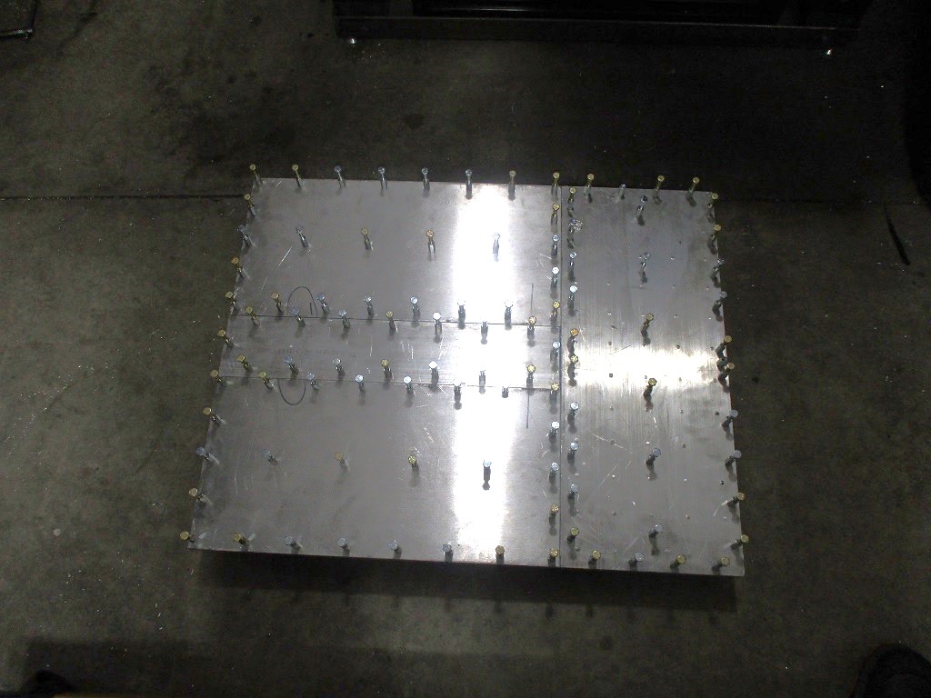
Added 3 more studs on each of the sides of the pan to help lock the pan to the concrete slab. Just some 3.5" long carriage bolts:
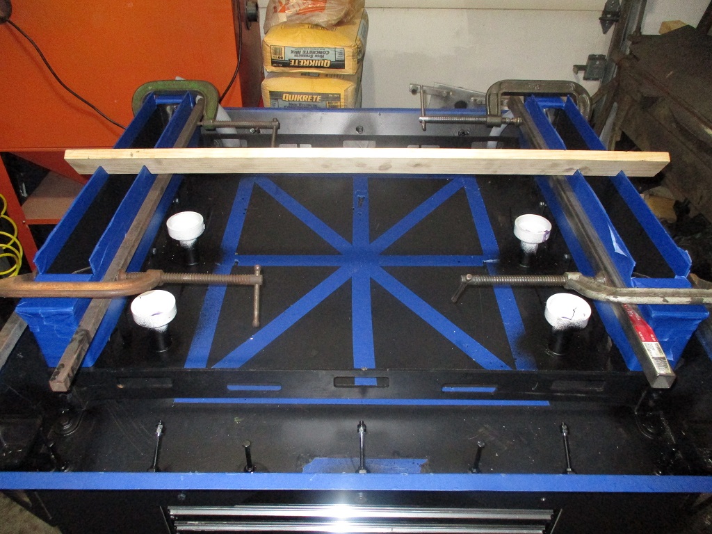
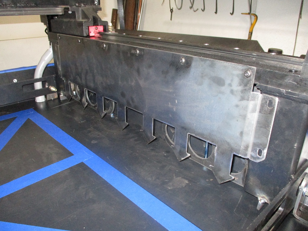
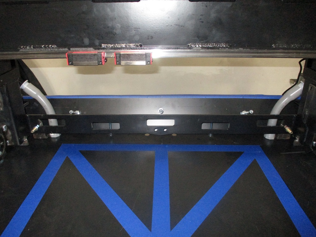
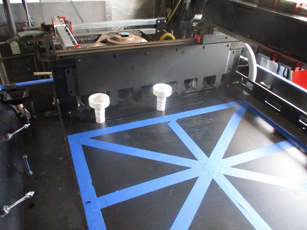
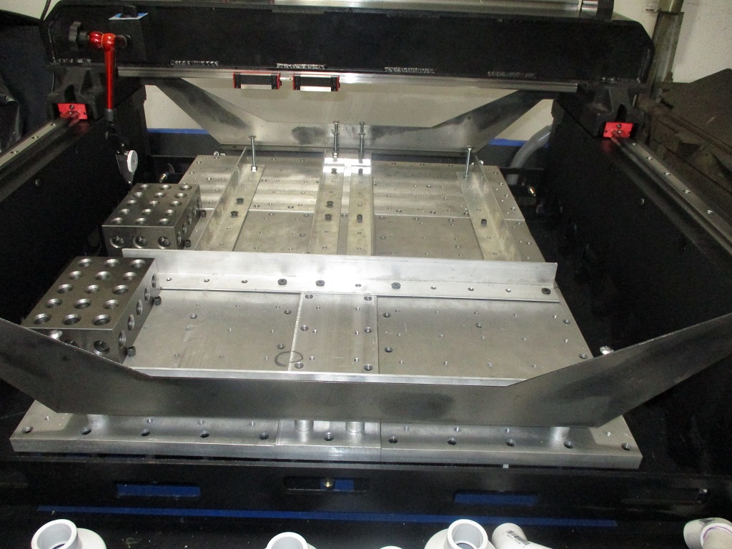
Then I started mocking up the Y and X rails primarily to start thinking about how I am going to run the cables. I was able to move the X-rail up and back the length of travel of the y-rail with my pinky finger. The blue tape in the center is my planned oversized 24x30 base plate.
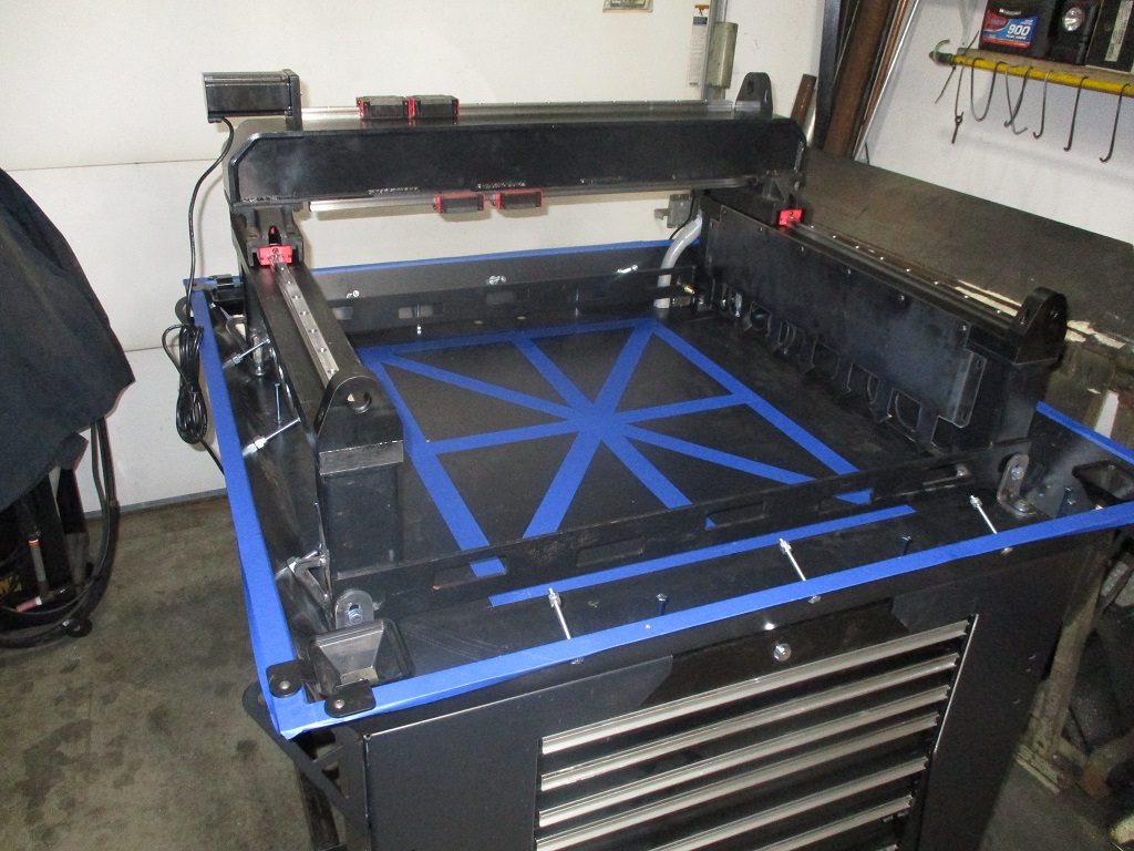
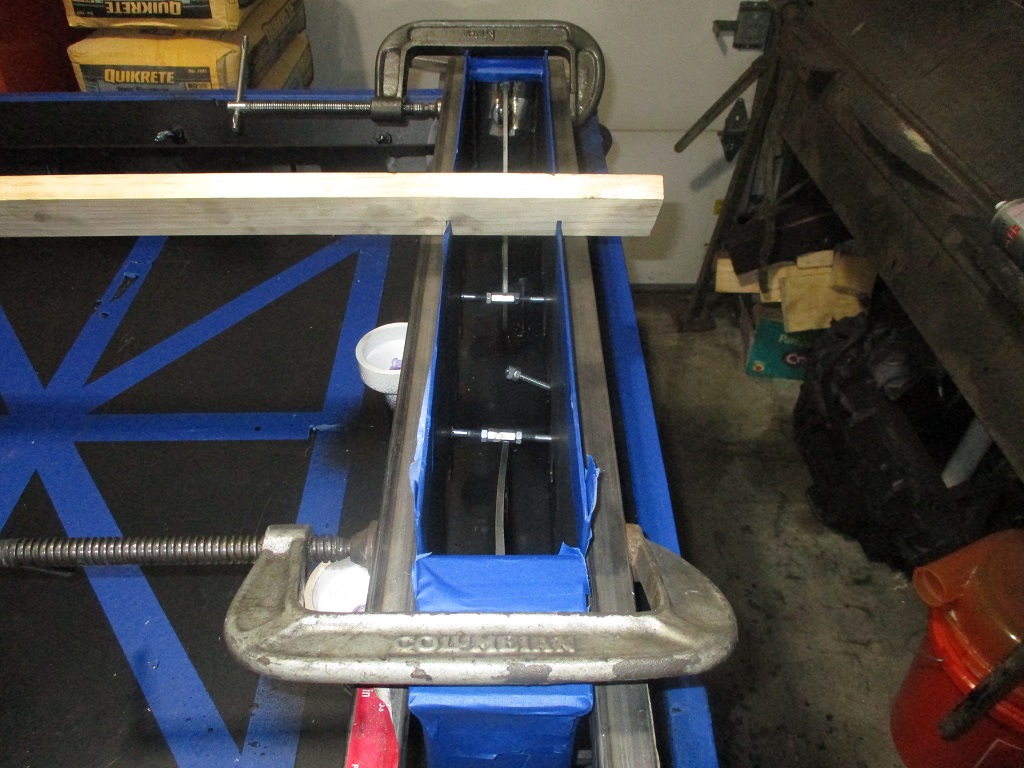
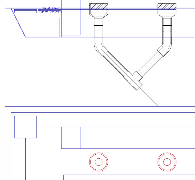
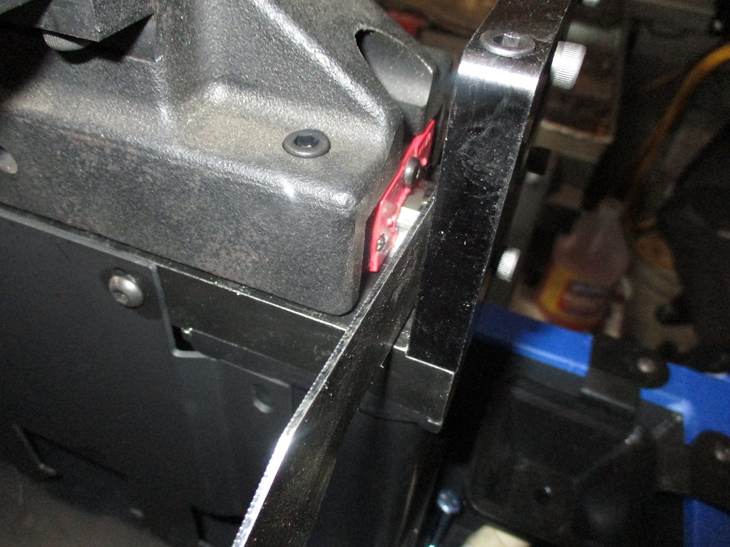
For the Y-motors, all cables will be routed through some PVC conduit under the motors and through the concrete base. I need up upsize at least the left side to 1" from 3/4" so that I can run the X rail cables through it as well. In this picture you can also see the bracket that holds the rear of the Y-rails (one per side).

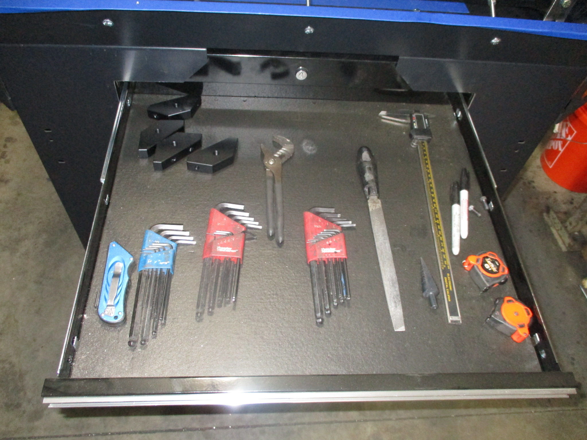
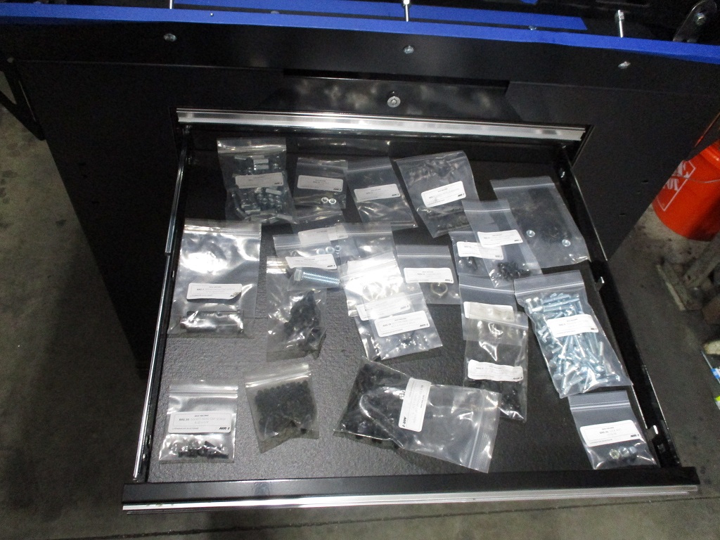
The tool box is already coming in handy…
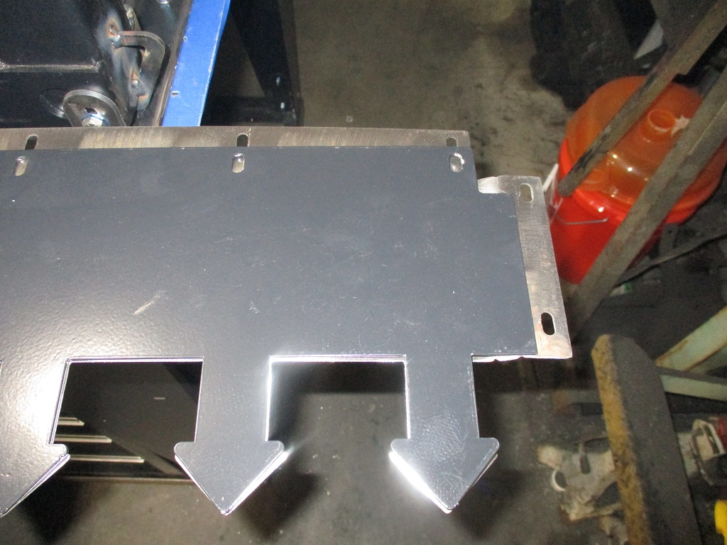
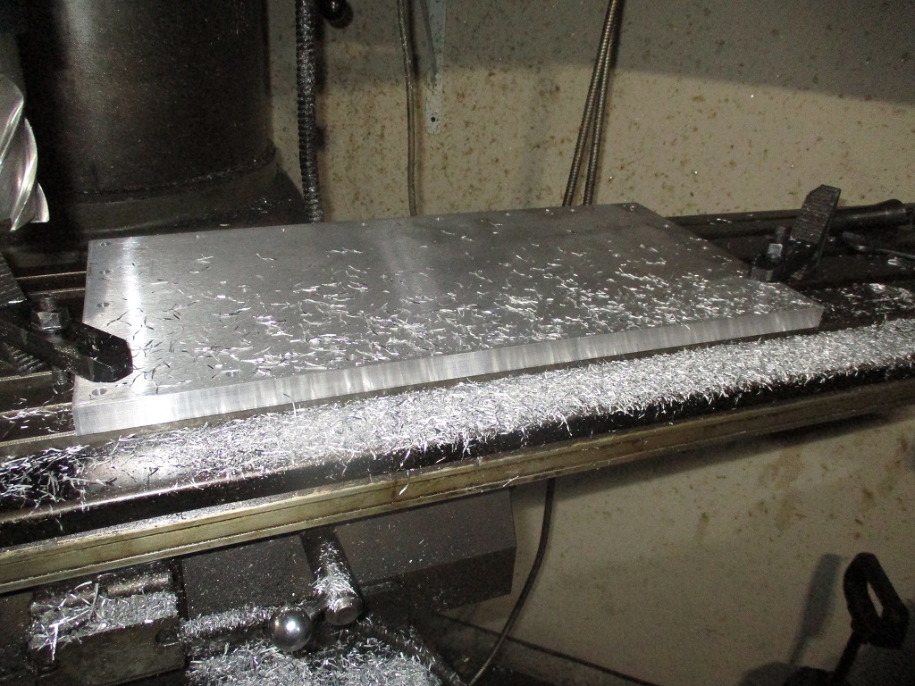
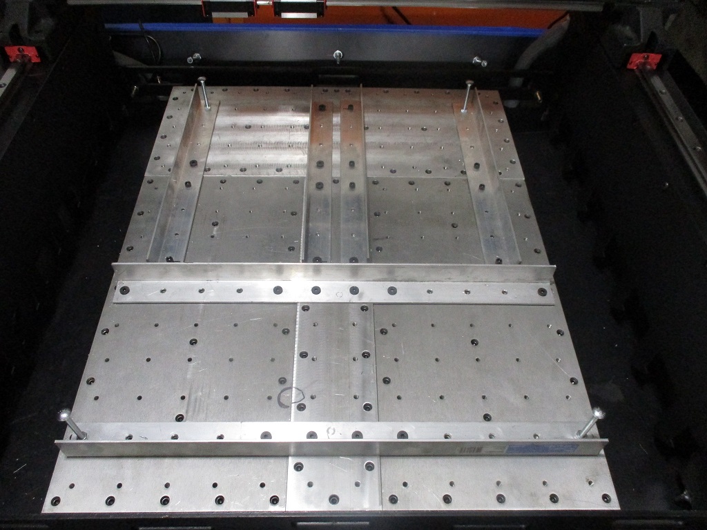
Started working on the oversized base plate. First thing I noticed was the rough cut perimeter of the base plates was not square with the 2x2 hole pattern, so I put them both on the mill to square all the sides to the 2x2 pattern.
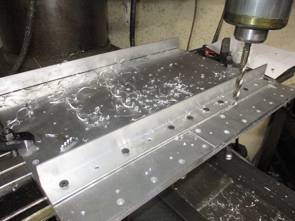
Once they were square, I mocked up the 4" spacer piece and checked the hole centers… and needed to take about 0.095" off in total between the two inside surfaces to keep a constant 2x2 pattern across all the plates. Once that was done, everything was bolted/clamped and started drilling out the pattern on the 4" center plate. Once I had some locating holes for the 4" center plate and bolted it into place, I trued up both ends.
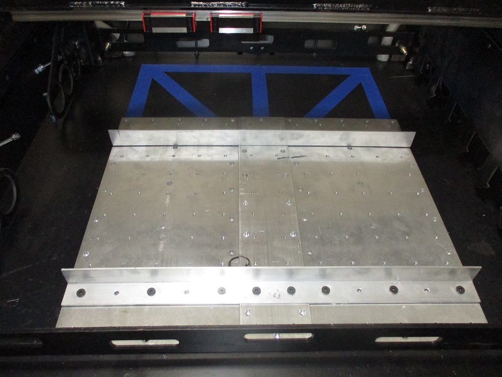
Here is the front portion of the enlarged baseplate setting in the pan. I need to do the same work to the 24x10 plate for the rear.
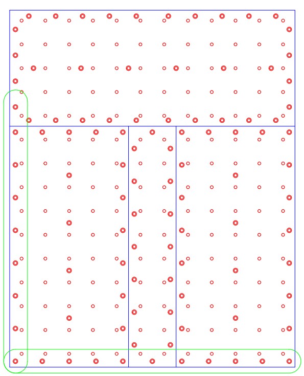
I did change up the anchor pattern on the 4" and 10" plates in my drawing. Originally the anchor pattern was mirrored from the current plates, but then I thought the anchors would be too close and might get hung up on the concrete rocks. So I offset them to increase the spacing between anchors.
Now I need to start working on the 24x10 plate…
|
|
|
|
fieroguru
|
FEB 13, 09:06 PM
|
|
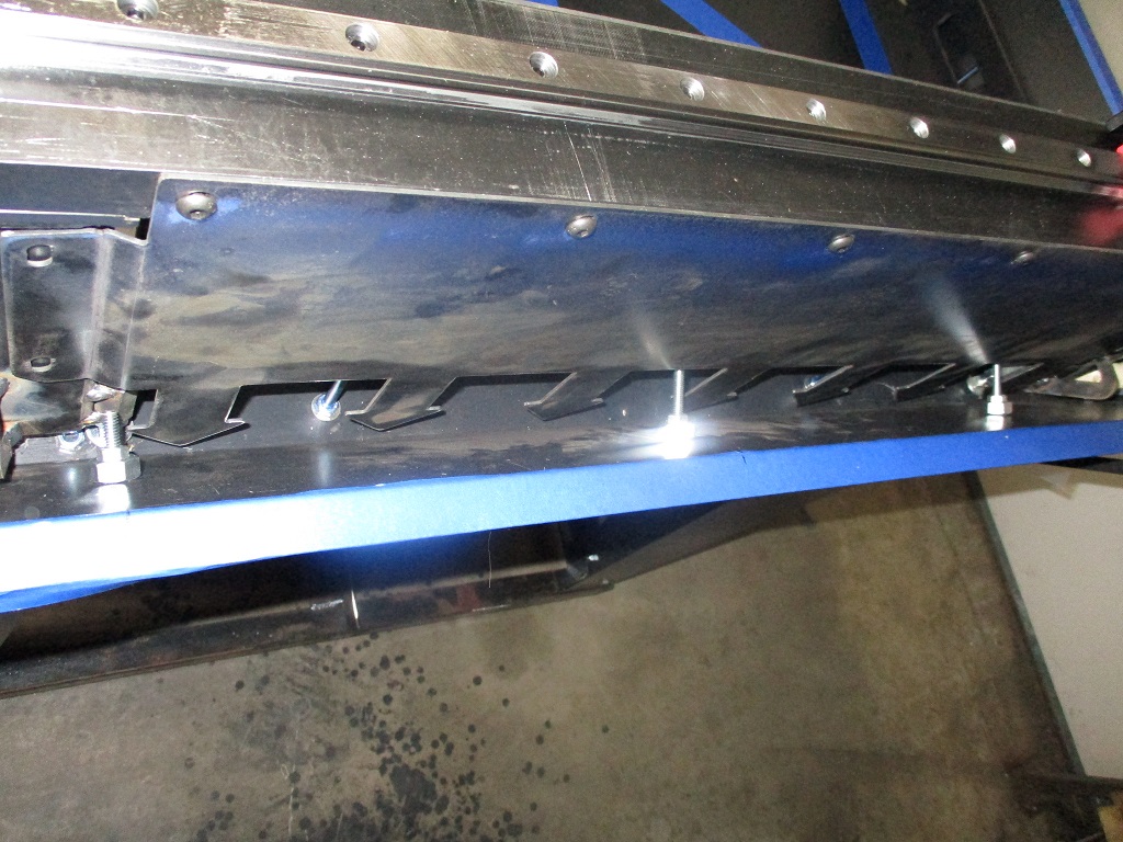
Base plate modifications are complete:
Also working on some additional center drains:
|
|
|
|
fieroguru
|
FEB 18, 05:00 PM
|
|
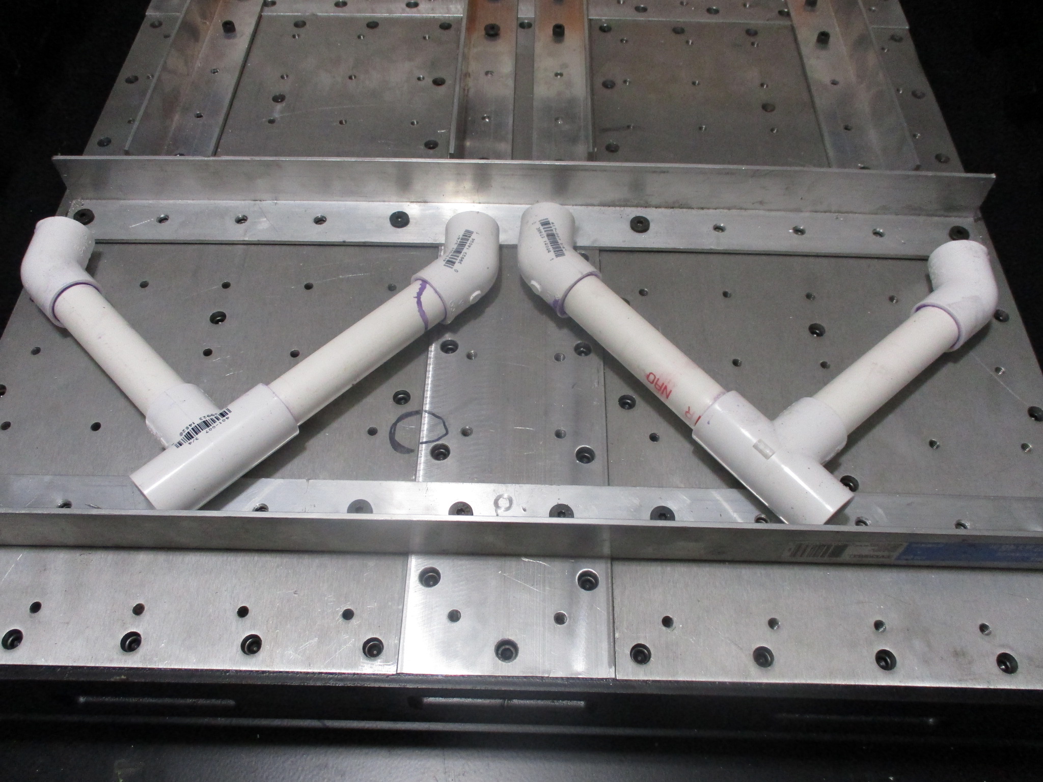
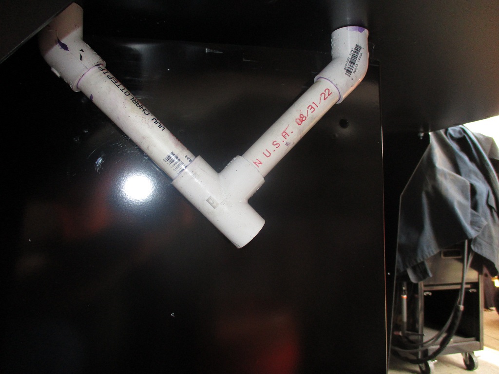
Finished up the cable PVC tubes. Kept the 3/4" on the right, but switched to a 90 and a 1" 90 on the left. The 1" is large enough to feed 3 motor cables through.
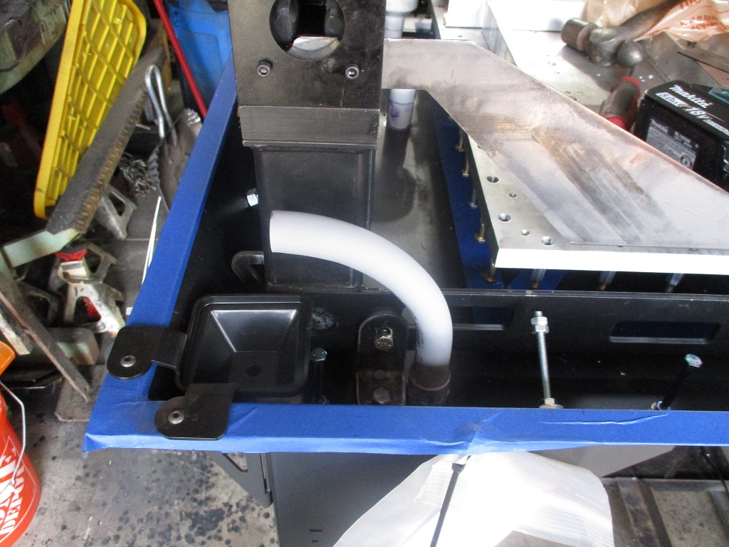
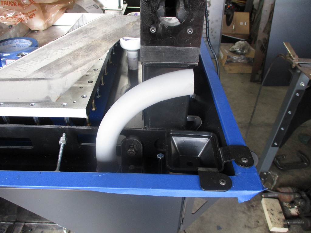
Installed the center drains after trimming down the overall height of the 3/4 to 2" reducers.
Drilled an tapped all the extra holes in the new Y-rail side plates.
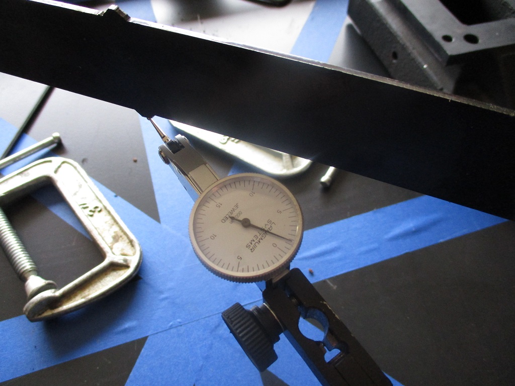
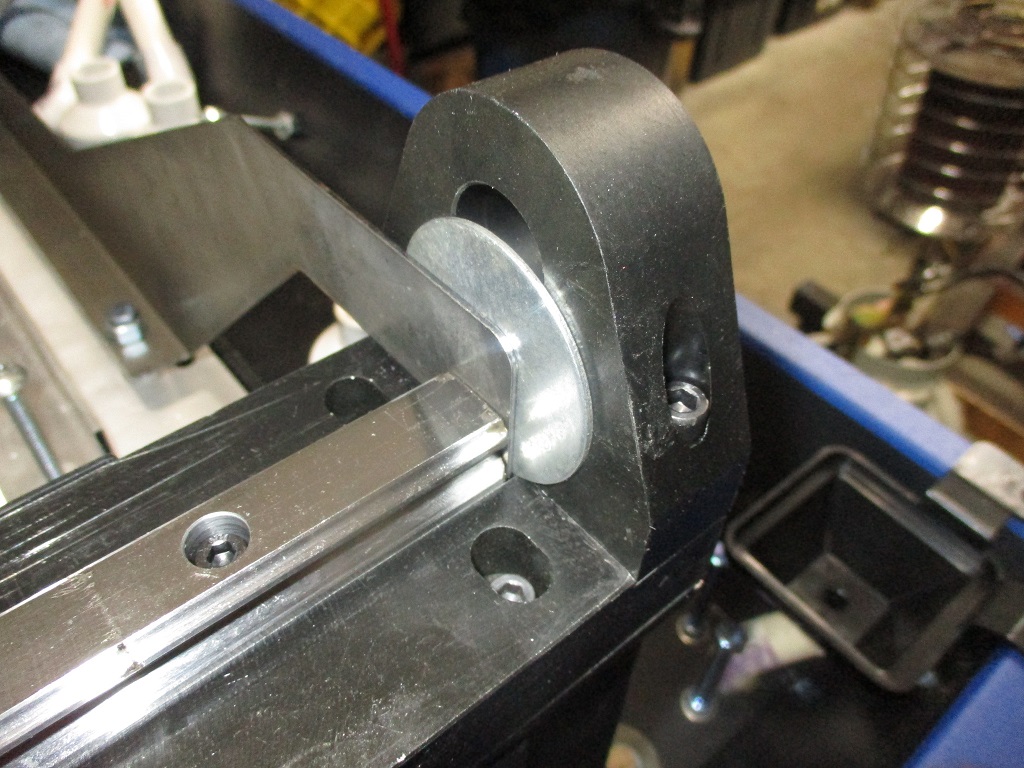
Also figured out how to properly locate the baseplate in the concrete and keeping the 2x2 pattern true to the left Y-rail. Used the supplied Langmuir baseplate brackets, with a 3/4" spacer to account for the raised rails. Then pulled the Langmuir brackets to the right so they are tight to the right side of the left rail. Then installed some bolts, 2x4x6 blocks, and ran a dial indicator down the length. Loosened the bolts holding the Langmuir brackets to the baseplate and squared it up.
While planning for this, I noticed there was room for the Langmuir brackets to fit between the linear rails and the end plates. I used washers to close the gap and doing the placed the front of the plate right at 8 9/16". I did have to offset the rear spacer about 7/8" to make the Langmuir brackets fit the rear gap.
Now it is time to take the top plates of the y-rails back off , reinstall them and make sure everything stays true and will go back together. It need to be able to do this to allow the area between the Y-rail side plates to be filled close to the top with concrete.
|
|
|
|
fieroguru
|
MAR 03, 06:56 AM
|
|
|
|
|