
 
     |
| Trinten's SBC/F23 build - The work has begun! (Page 17/76) |

|
KissMySSFiero
|
SEP 20, 01:25 PM
|
|
|
how's this thing coming along? ------------------
SSFiero@Aol.com 87 Gt-5spd-62k miles.

|
|
|
|
Trinten
|
SEP 20, 09:10 PM
|
|
It's actually going great! FieroGuru has sent me a few things in PM to see what I thought about them. He also enlarged the oil return hole on the side of the block, which is great, and makes me feel a bit more comfortable since the engine builder put in a high flow oil pump, so I won't be punishing the pump with (as much?) backpressure.
And of course FieroGuru has his own stuff to do, he was doing some work on one of his brake projects, and he had gone to an event to put his car through the paces. He's been outstanding about sending me updates!
Right now I think he's also waiting for my clutch to show up. I had a 6-puck sprung hub ceramic clutch from Clutchnet. He didn't know how much material was left on the face (compared to a new one), and Oleg didn't get back to me on that question, so I ordered a new one anyway, figure I'll keep my old one as an emergency backup.
So please stay tuned! 
|
|
|
|
fieroguru
|
SEP 22, 07:47 PM
|
|
Yeah, progress has been slow the last few weeks due to LS Fest and spending time on my car, working on quite a few brake kit orders, and last week we had plant dinners on all shifts on 2 days (4 crew plant) so I was working some very strange hours... However Vince's engine did get some love this weekend.
I had already installed the timing cover for the last time, made a timing notch for TDC (just to assist with positioning the cam sensor), and installed the oil pan with a new gasket:

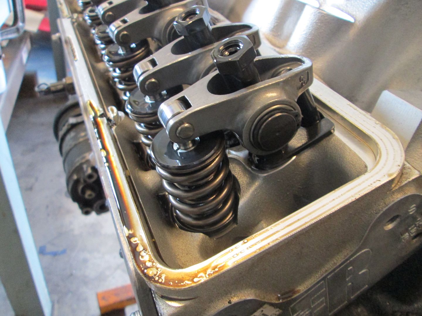
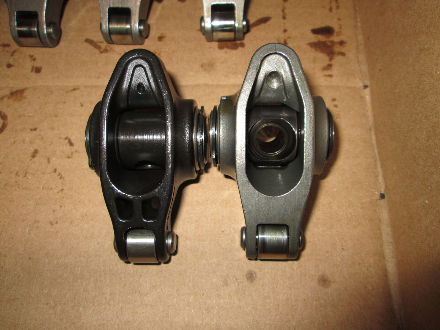
Next I wanted to button up the valve covers, so I swapped out the roller tipped 1.52 ratio rockers with the 1.6 roller tipped rockers. With these, his roller camshaft specs are: 230/236 .576"/.570" with a 113 lobe separation (Comp Cams 280XFI HR13 part # 07-467-8). With his AFR heads flowing more at .600 than .550, he should see some additional peak HP and possibly push this thing over 400 wph (371 whp was the previous tune). Here are the 1.5 roller rockers:
Comparison pic (1.6 on the left):
Installed:
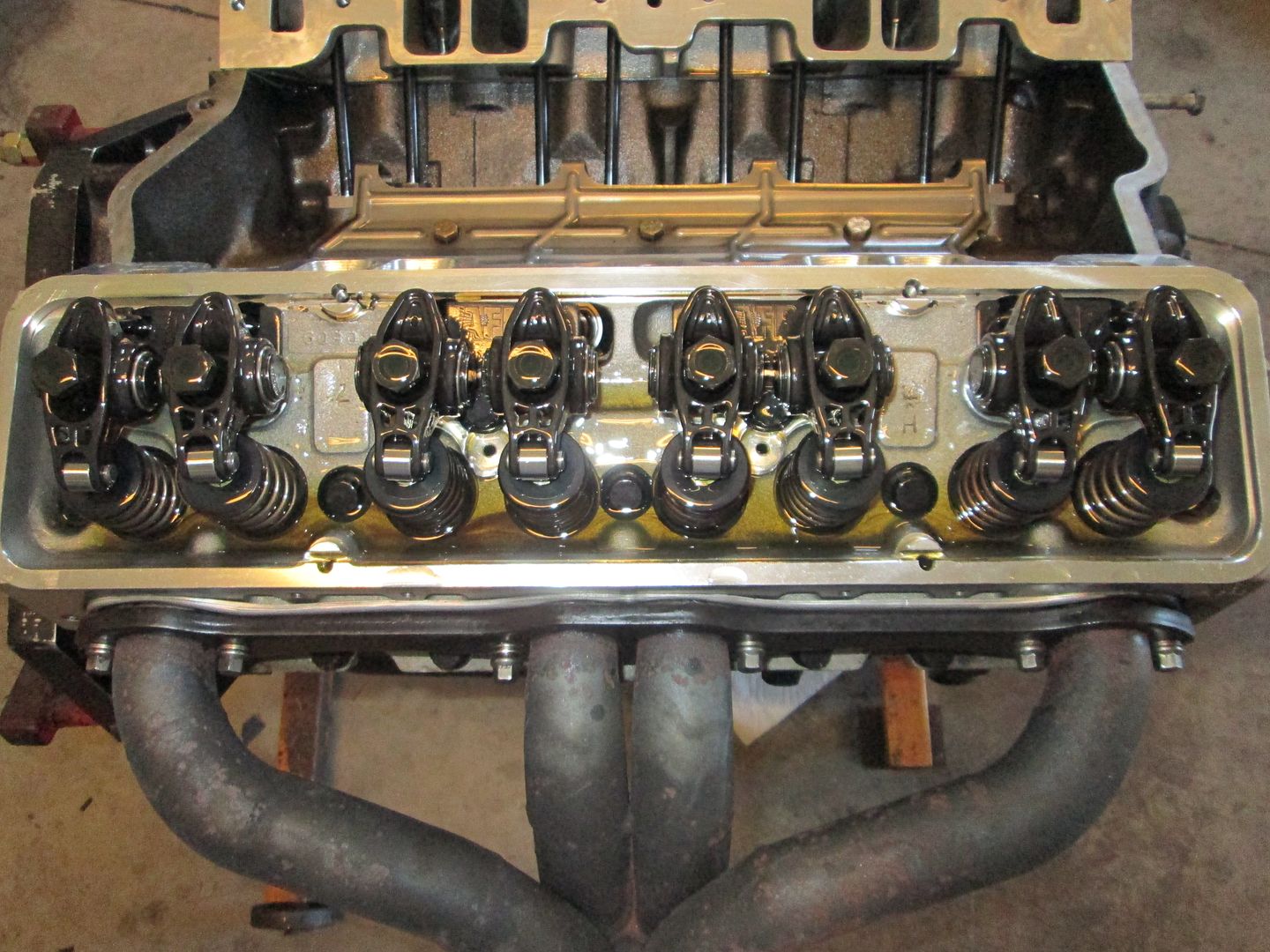
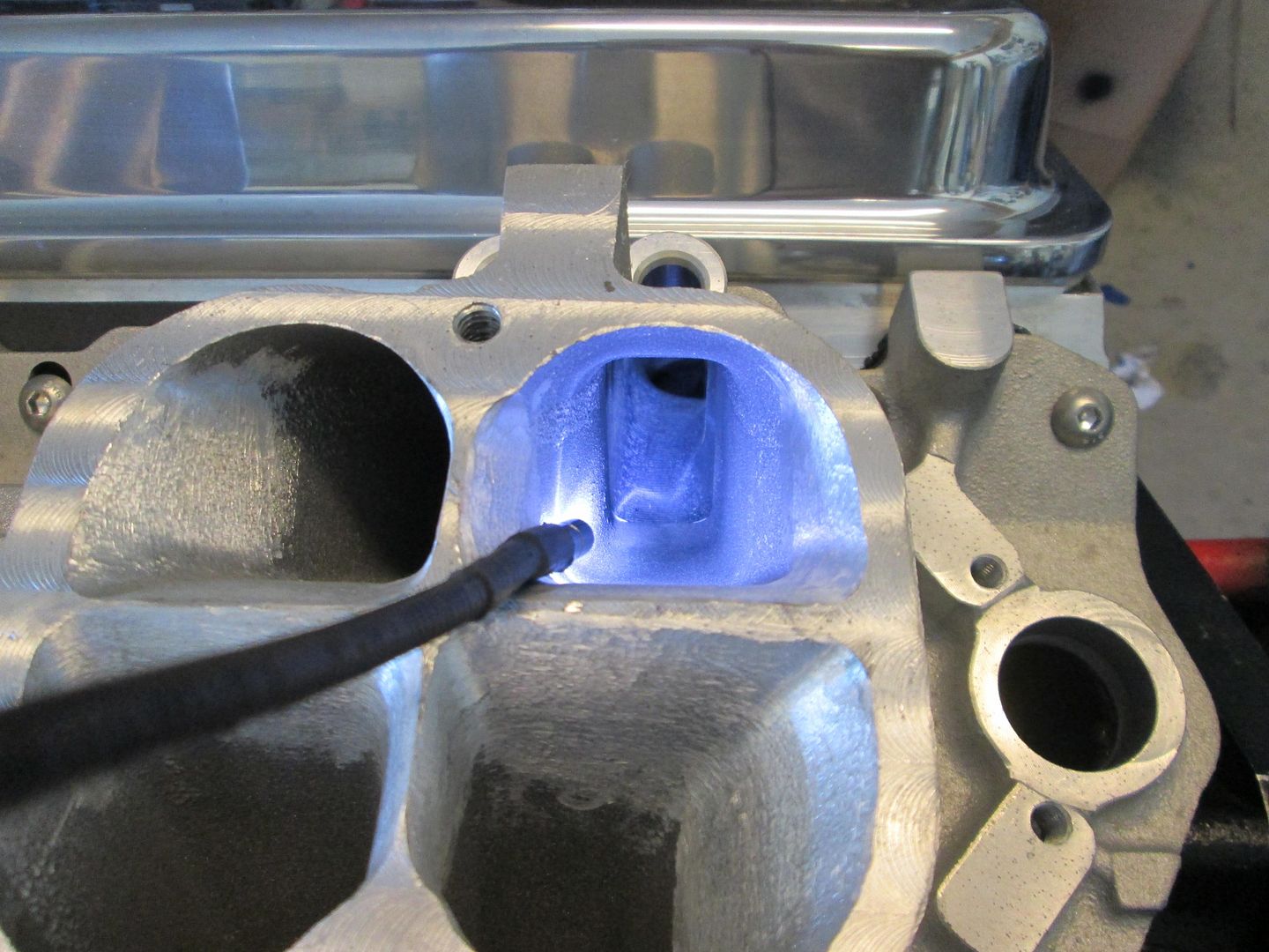
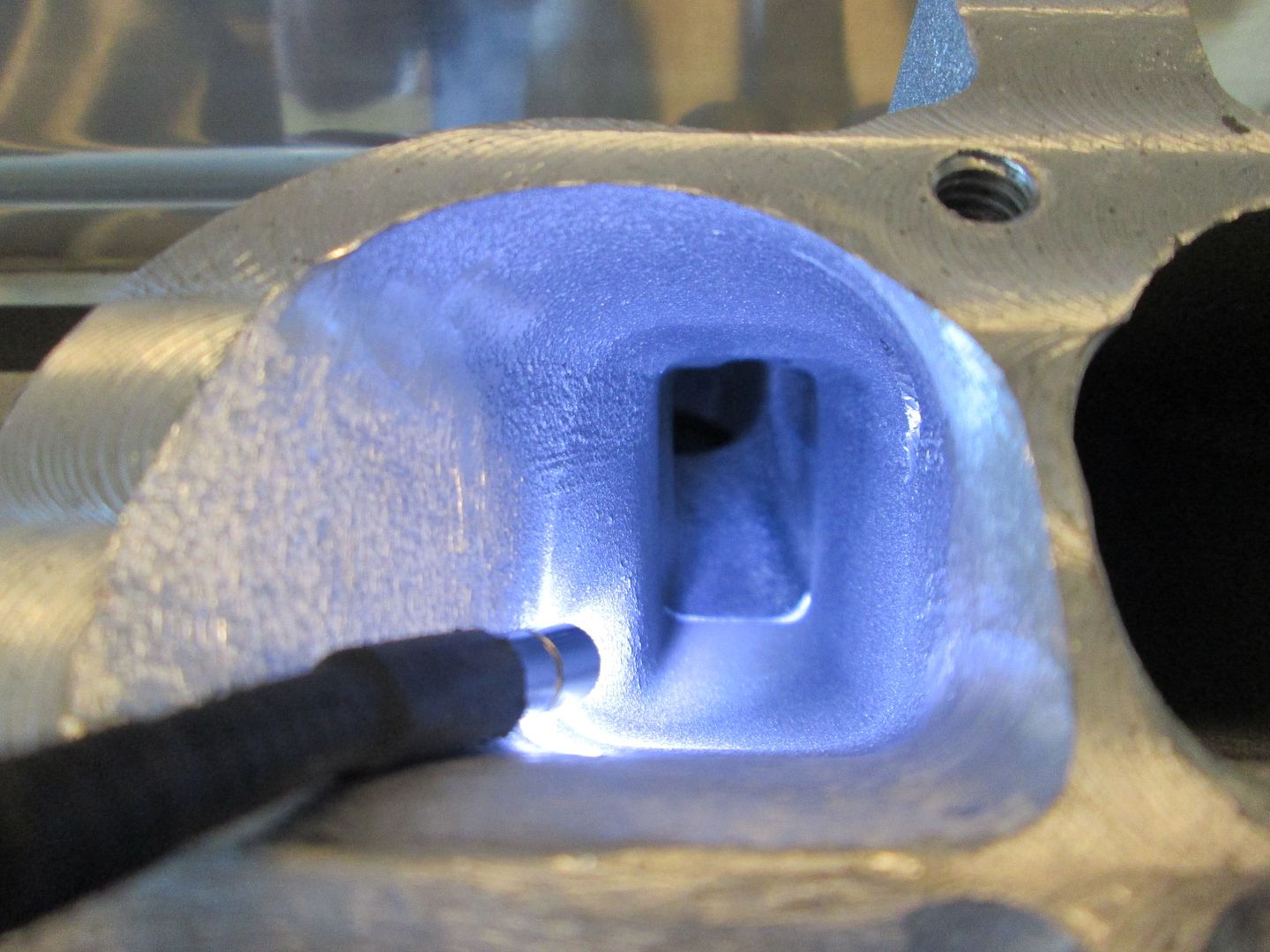
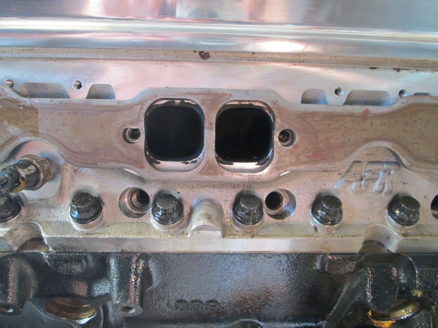
The bolts for the valve covers were about 1/4" too long to tighten the valve covers, so I shortened the 8 bolts, dumped a quart of oil over each bank and installed the valve covers. Next was to install the lower intake, I dumped 2 quarts of oil over the lifters, installed the intake gaskets, installed the intake, lined up the intake runners to the head ports (with a tunnel ram you can "see" the alignment), then torqued it down. All the ports looked like these two with just a slight portion of the lower corners of the head protruding past the ports on the HSR.
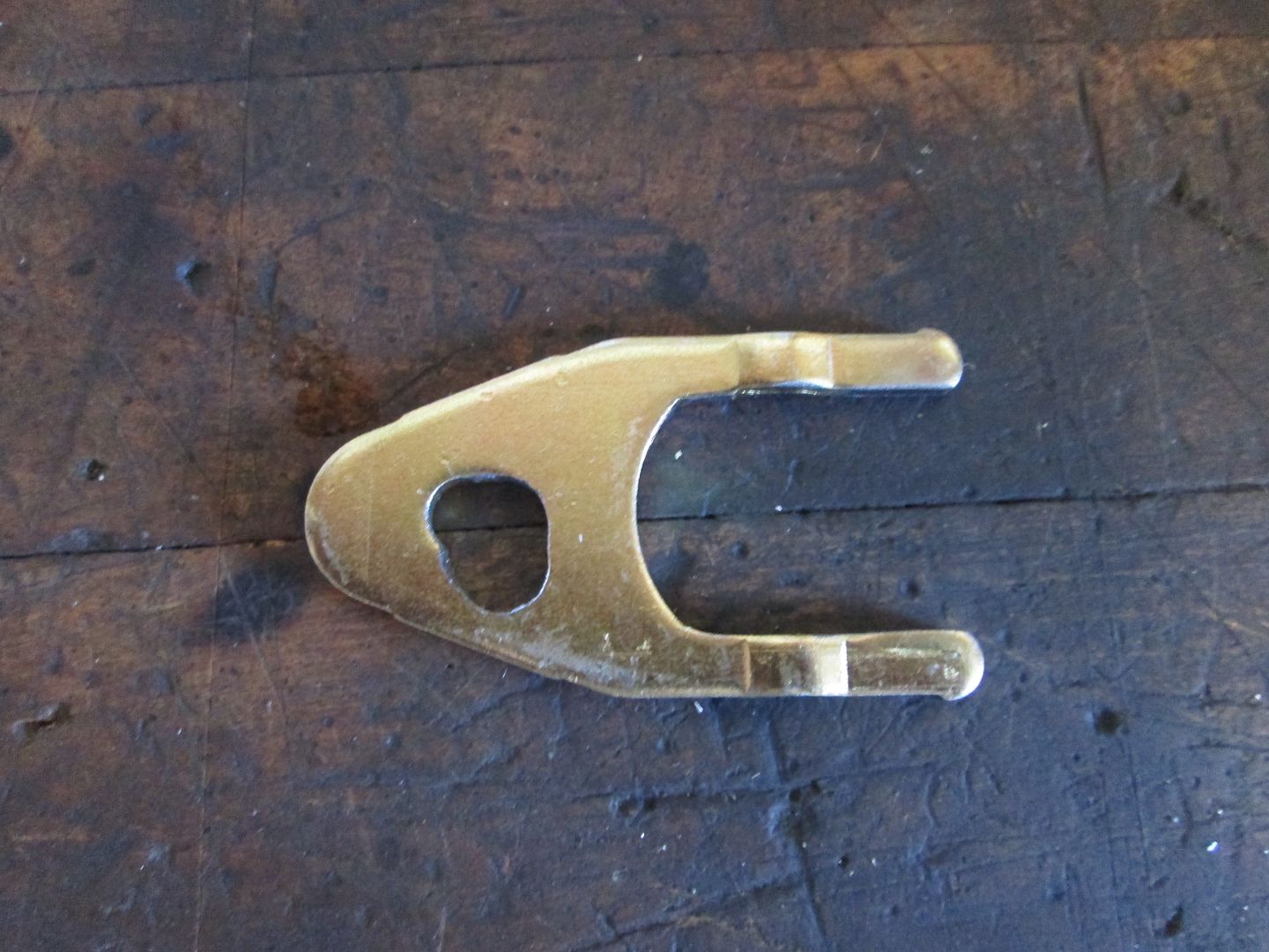
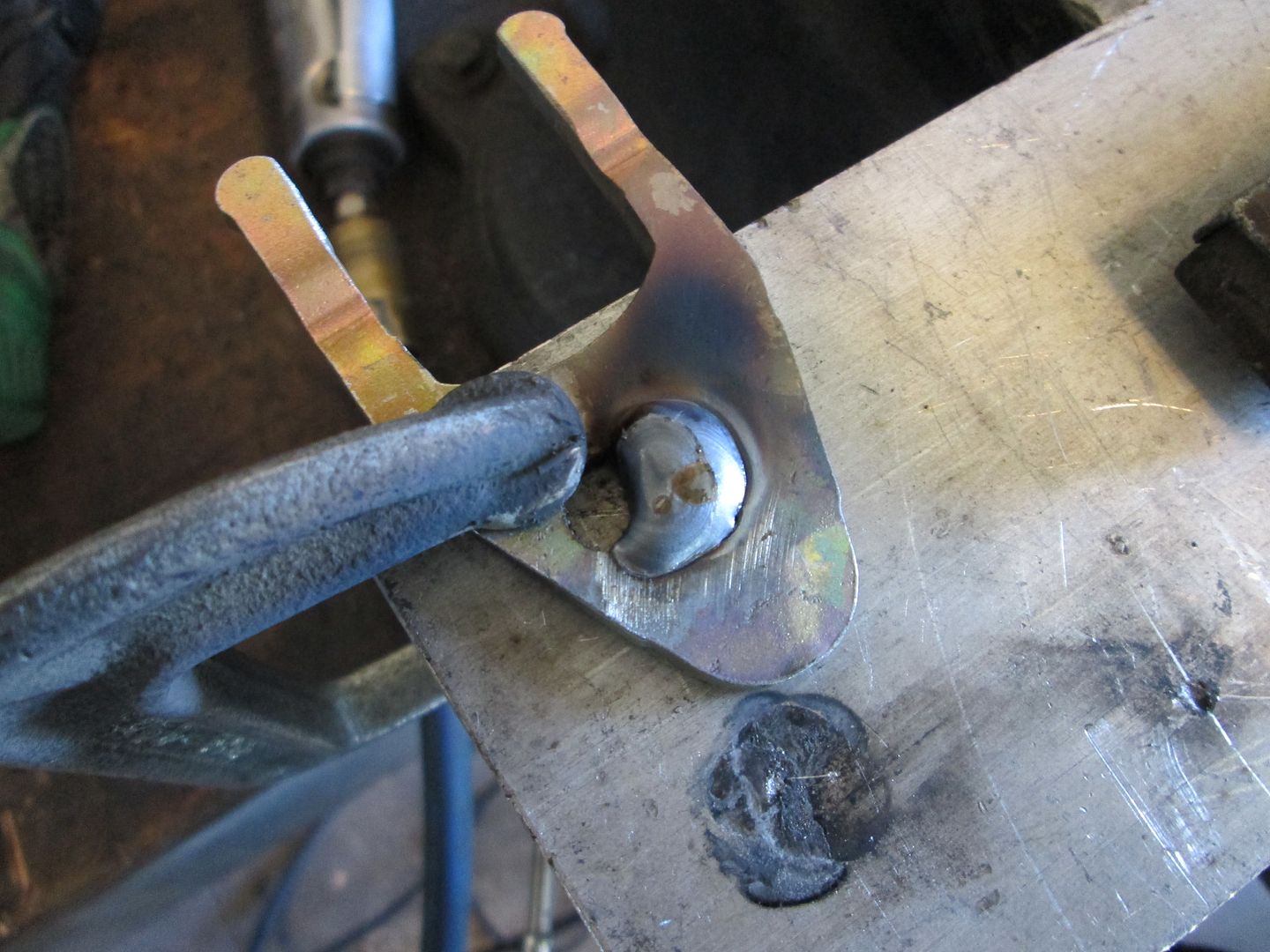
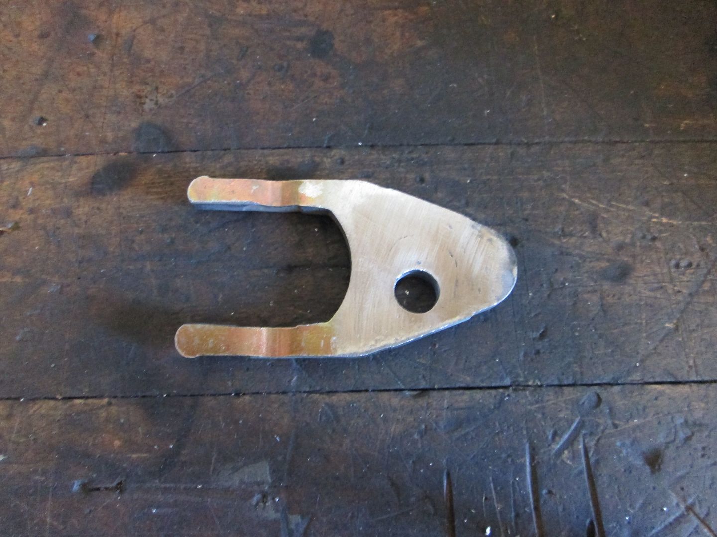
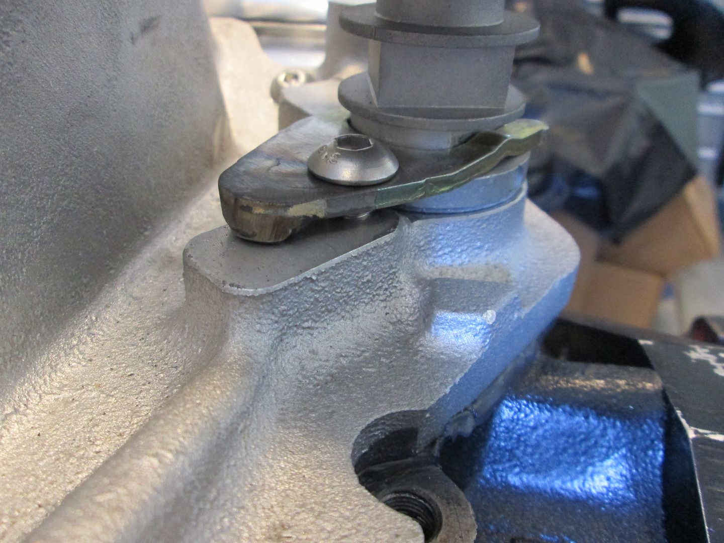
All of this work to button up the engine was to finalize the cam sensor location in the distributor housing. It took some trial and error to get the sensor lined up with the connector pointing the direction I wanted it, but eventually got there. Then the hold down clamp had to be slotted to the right position, then the original hole welded up and smoothed, the bolt hole redrilled, and a pivot stand welded to the hold down... Now the cam sensor is aligned per the EFI Connection instructions!
Hold down slotted:
Filled:
Smoothed and redrilled:
Installed:

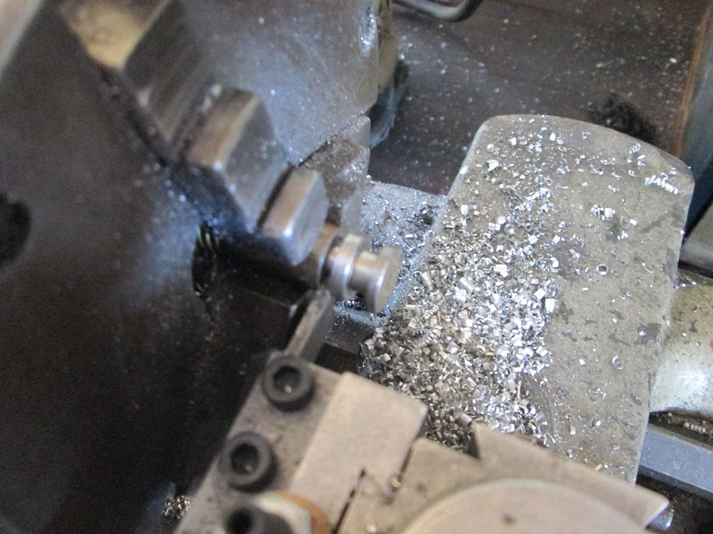
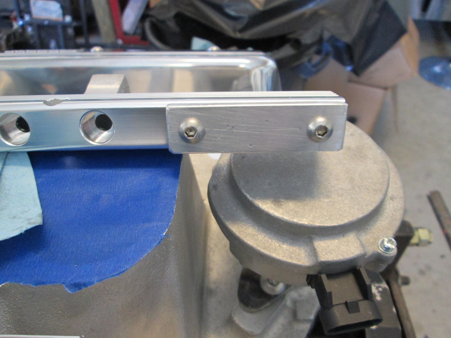
Next I set to work on the fuel rails. They are setup for a rail mounted regulator and I am converting them to returnless, so I needed to fill the regulator port. I turned a plug with the same o-ring groove as the regulator, fabbed up an aluminum bar to span the plug and keep it secure, then trimmed the stainless steel button heads to the right length.
Bypass regulator and open port:
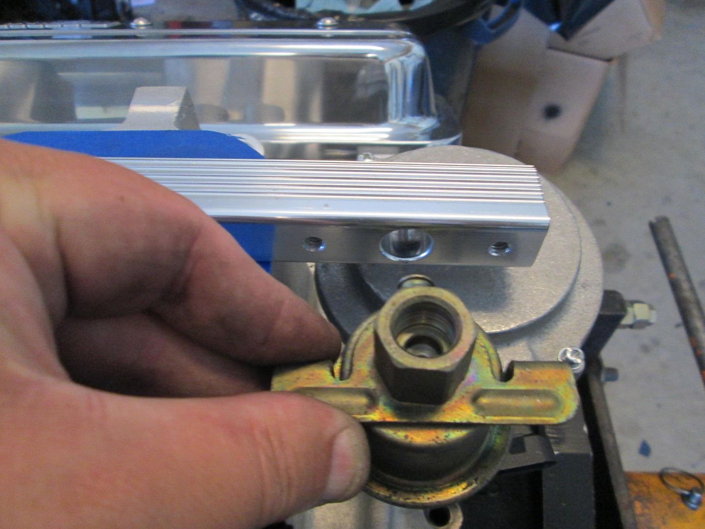
Turning a plug with o-ring groove:
Installed:
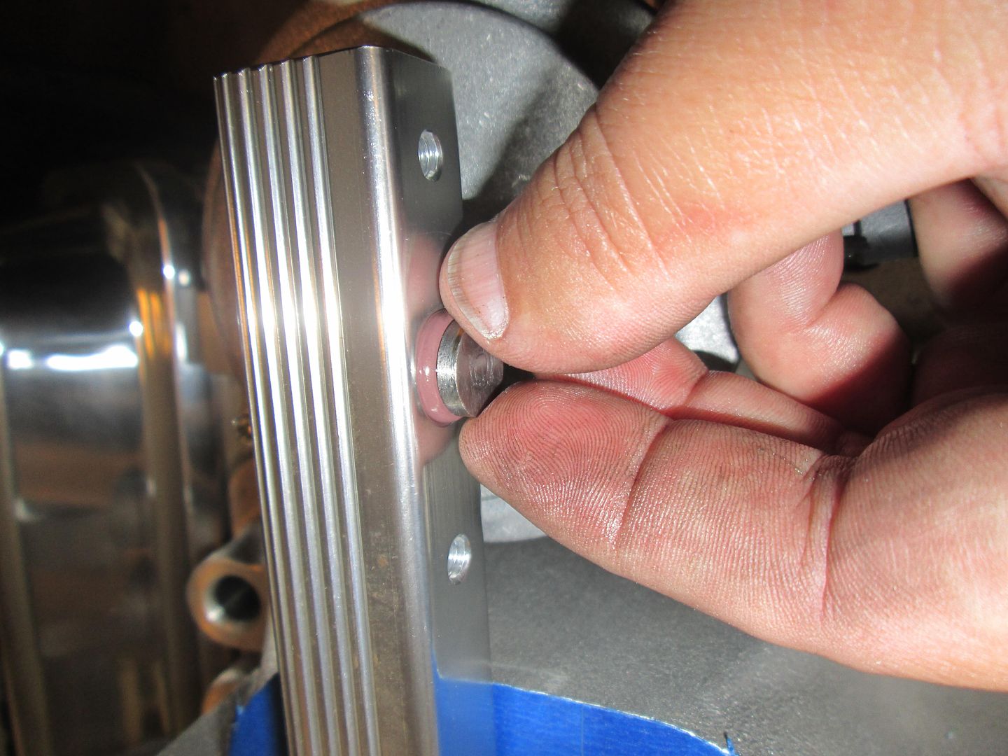
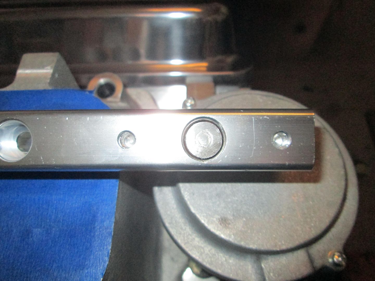
Capped:
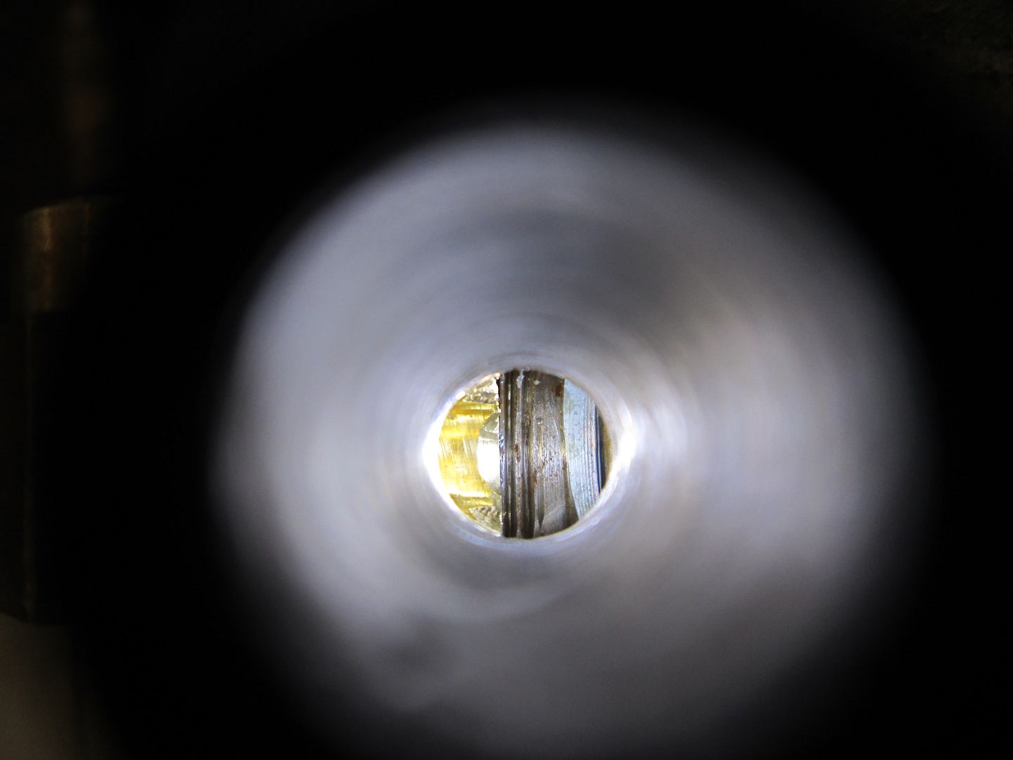
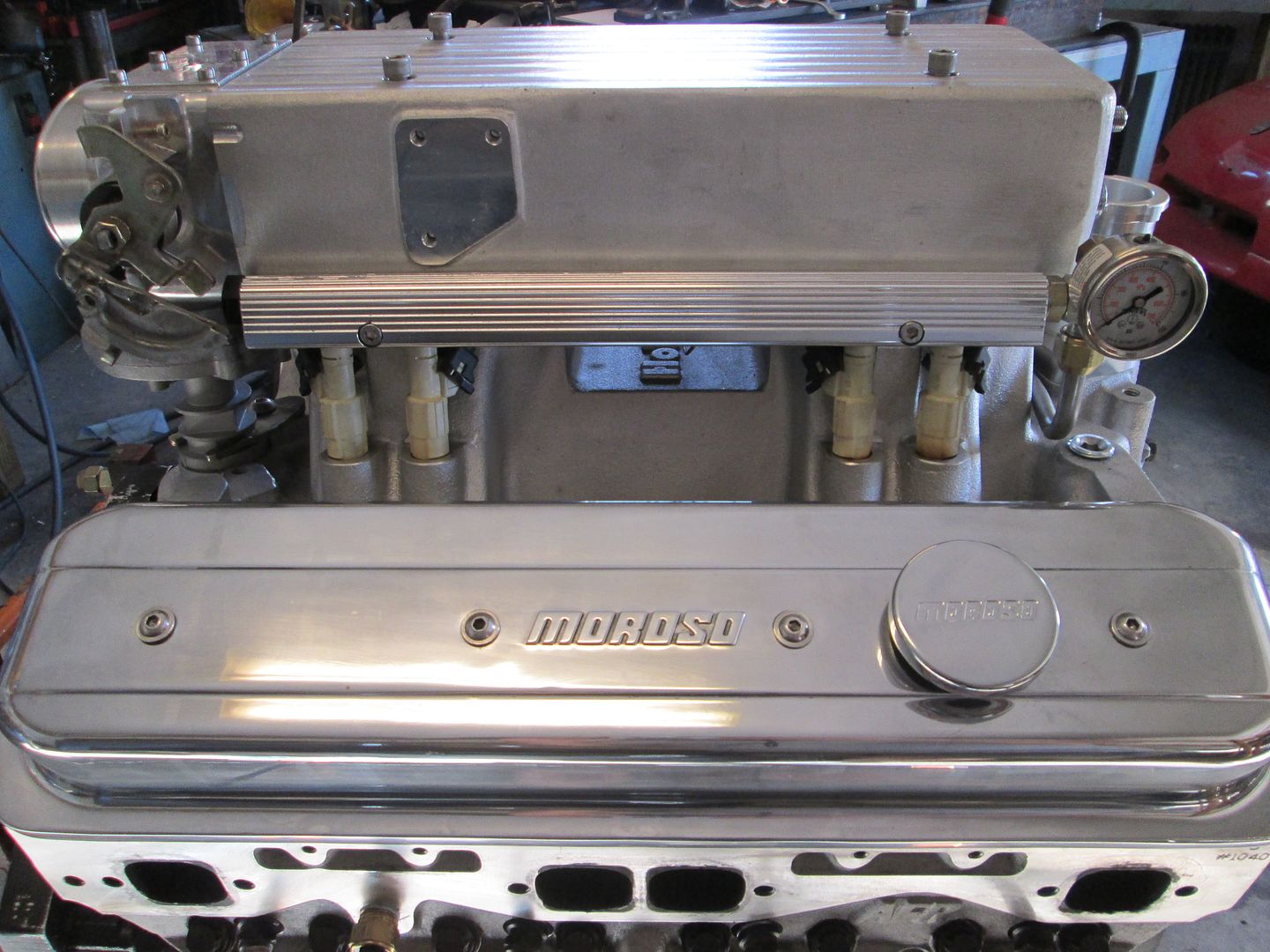
Next order of business for the fuel rail was to add the fuel pressure gauge. Pretty simple with the 1/8 NPT elbow, but when it was tight, the inner portion of the threads were partially blocking the port, so I drilled down through the fitting to clearance the part the protruded into the opening.
Threads protruding:
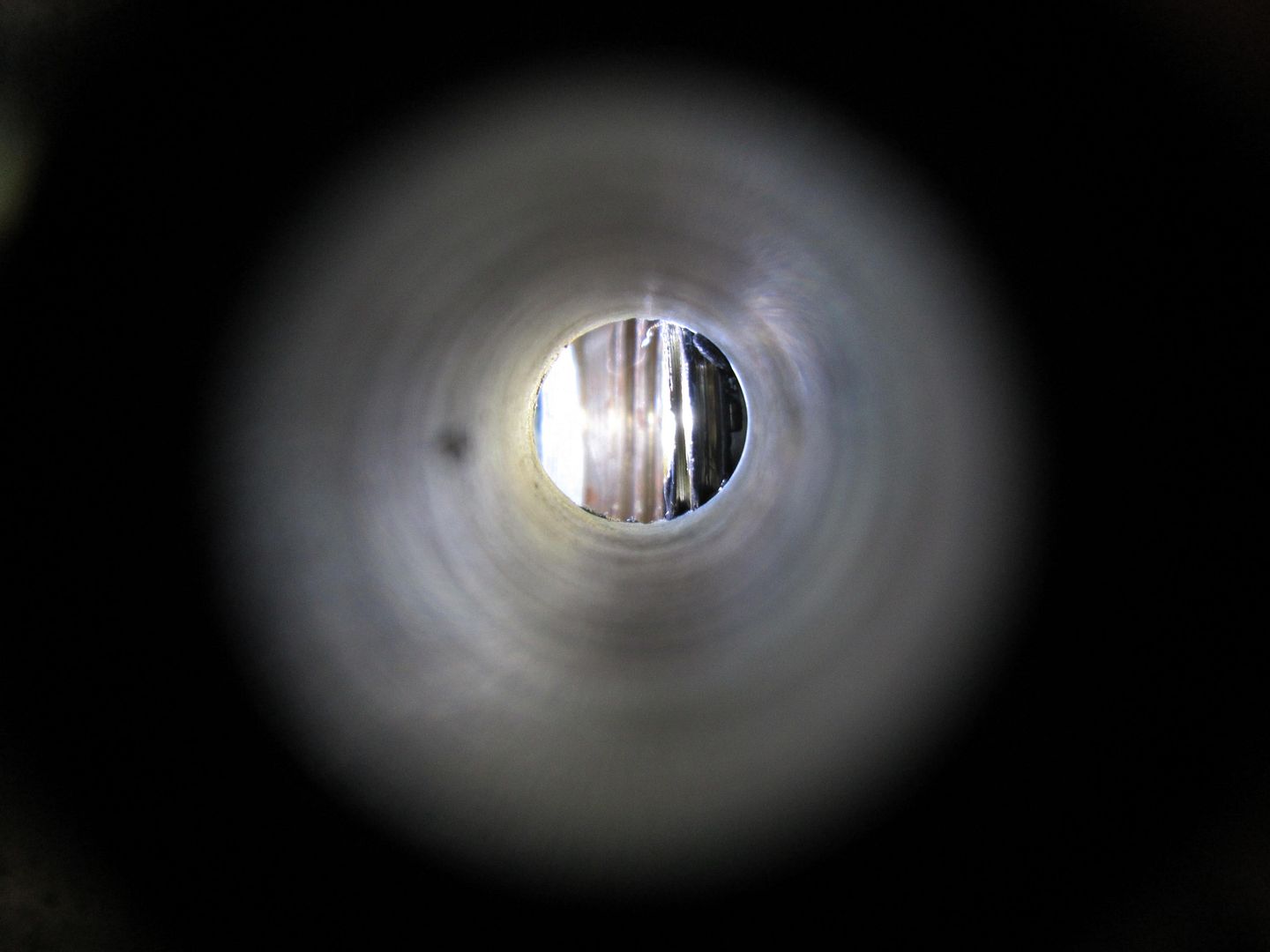
Clearanced:
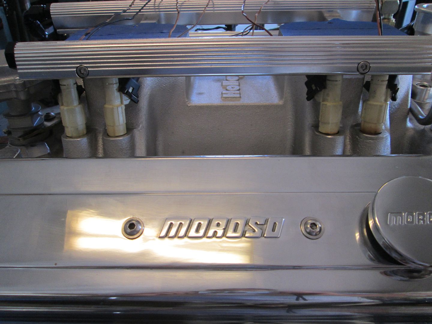
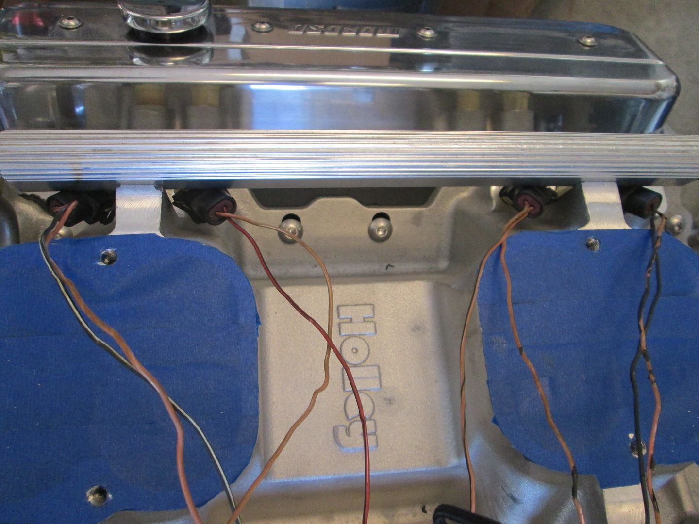
Then purged all the fuel rails and fittings with brake clean to remove any debris, installed the injectors (36# Bosch) and started playing around with wiring options to hide the connectors. Originally I didn't think there was any chance of flipping the connectors to the back side, but it works!
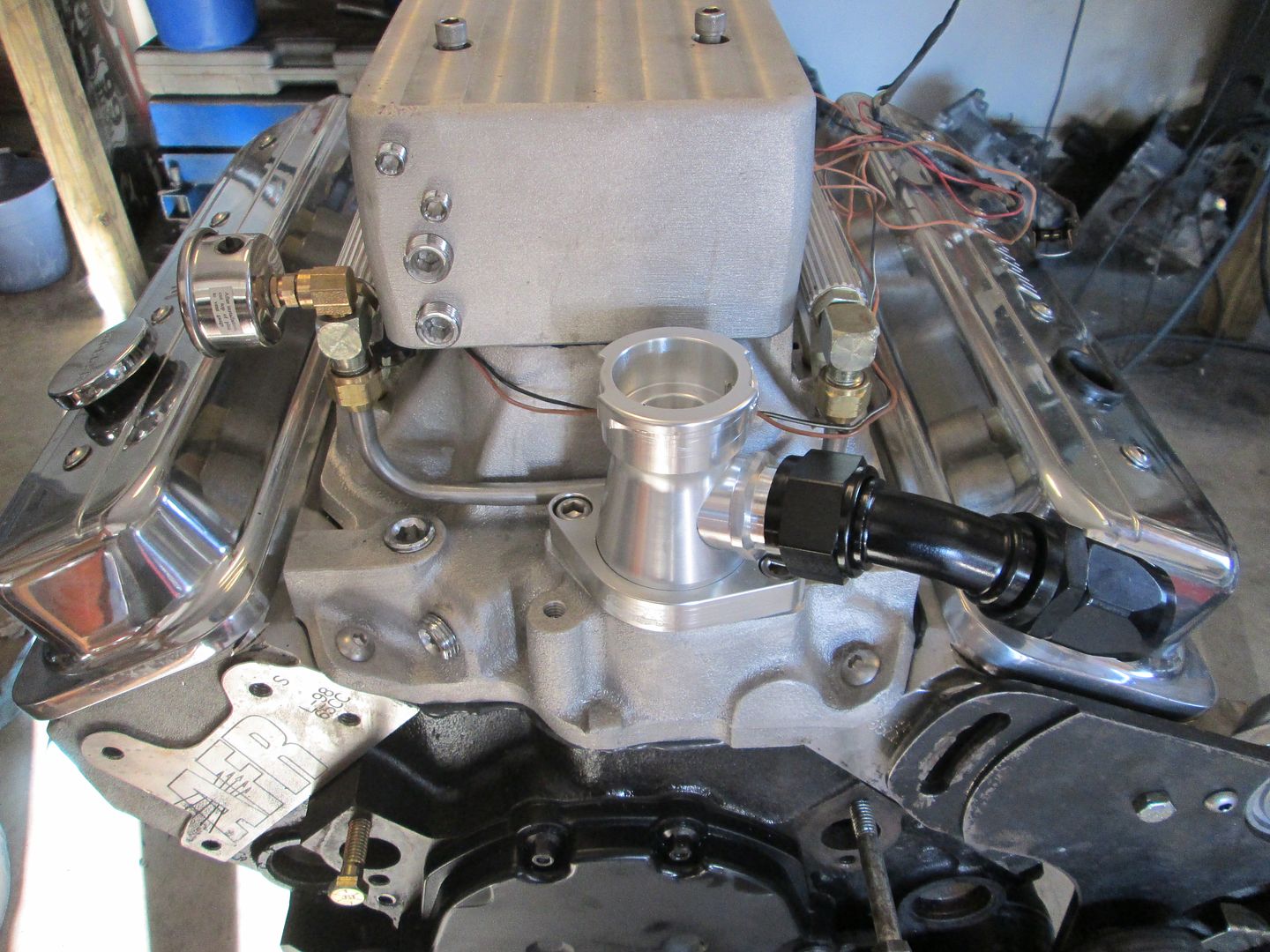
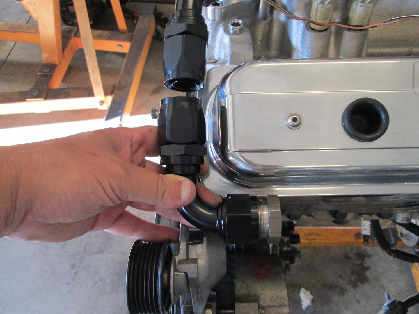
I am in the process of filling all the extra coolant ports and vacuum ports with chrome plugs. This picture also shows the coolant fill and the -16 AN fitting.
Here is the other -16AN elbow and a steel weld end, there wont be much length to the braided stainless steel hose... I will weld the steel end to some 1" schedule 40 pipe that will be the coolant crossover to the passenger side.
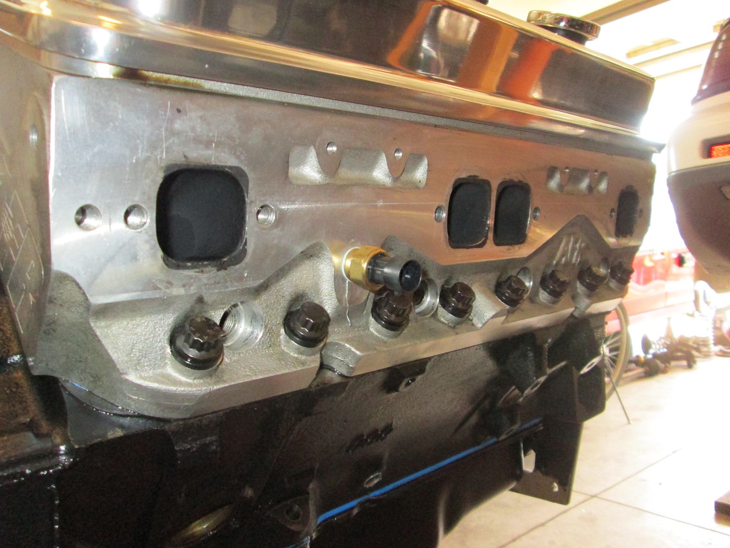
Here is a mockup of the 1 3/4" header flange to the exhaust ports on the heads (I have sense removed the stock fiero temp sender and capped that coolant port):
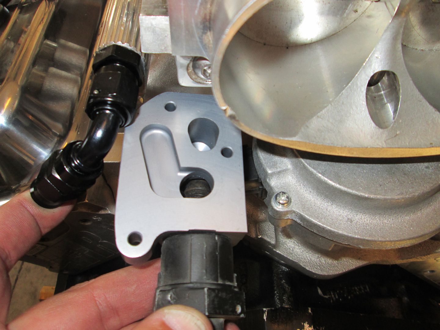
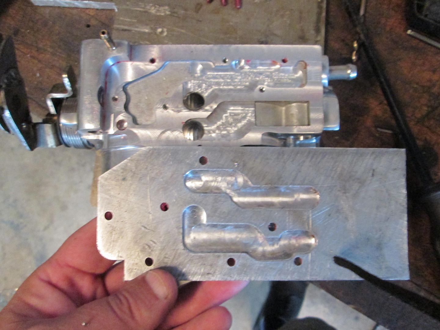
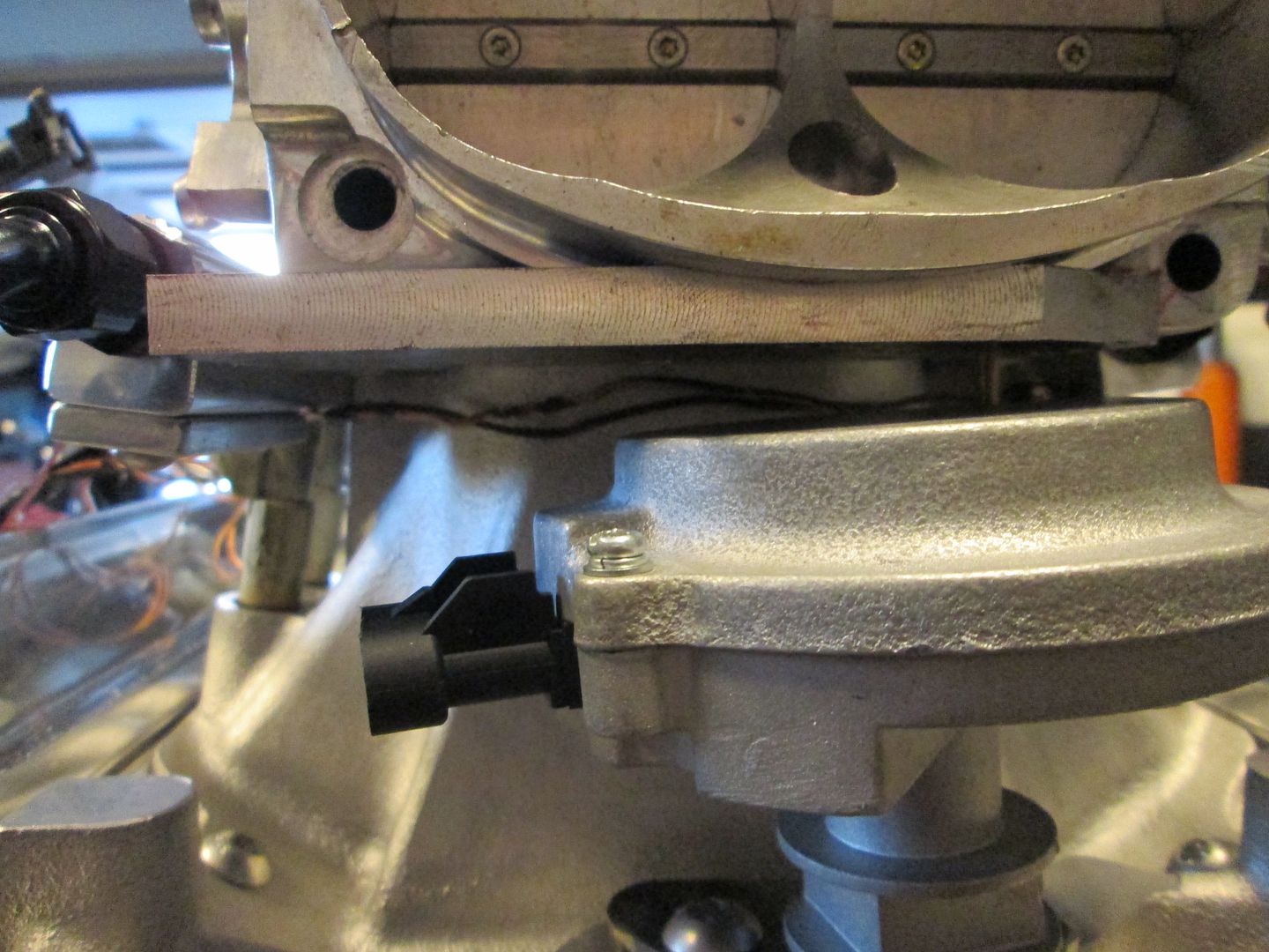
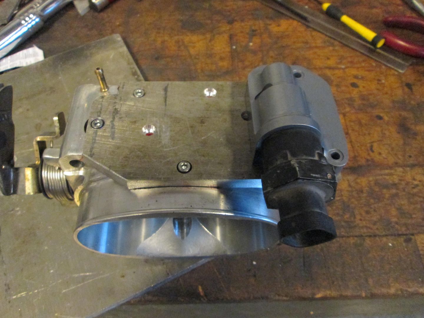
I think I also figured out a slick/relatively simple solution for the IAC housing that will not fit in the stock location. I plan to machine a 1/4" plate to cap off the complete underside of the throttle body housing and extend it out past the TPS side of the throttle body as needed. Then I will use and modify the existing passages under the throttle body (and machine some in the 1/4" plate), to create the air flow path to the new IAC position, which will be 90 degrees from the stock position and off to the side of the throttle body. This pic shows the new position for the IAC housing and the available room for a 1/2" plate:
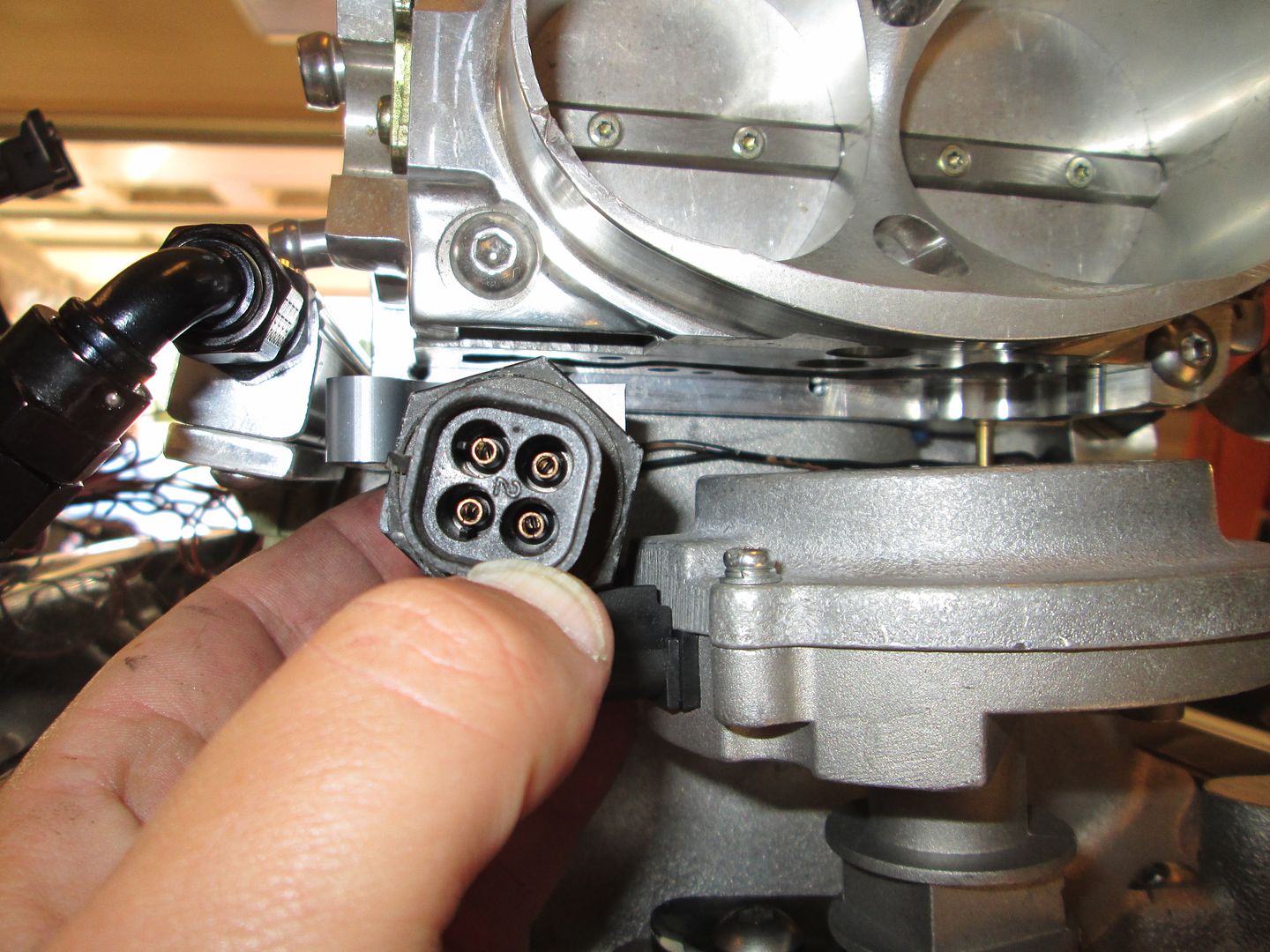
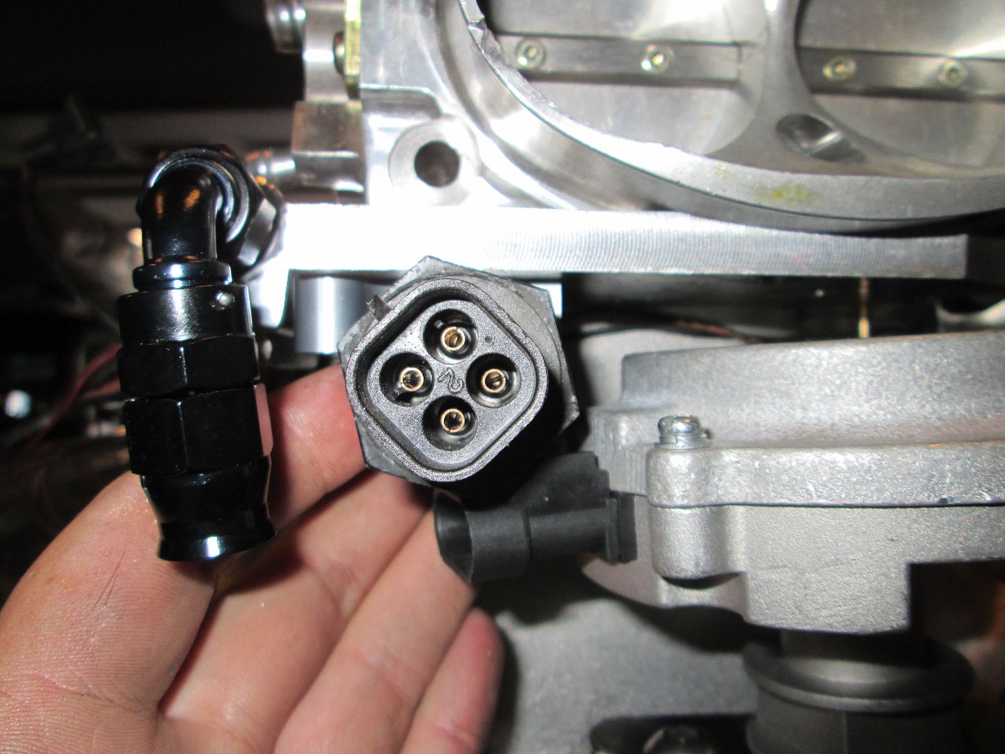
Here is a pic of the ports on the IAC housing:
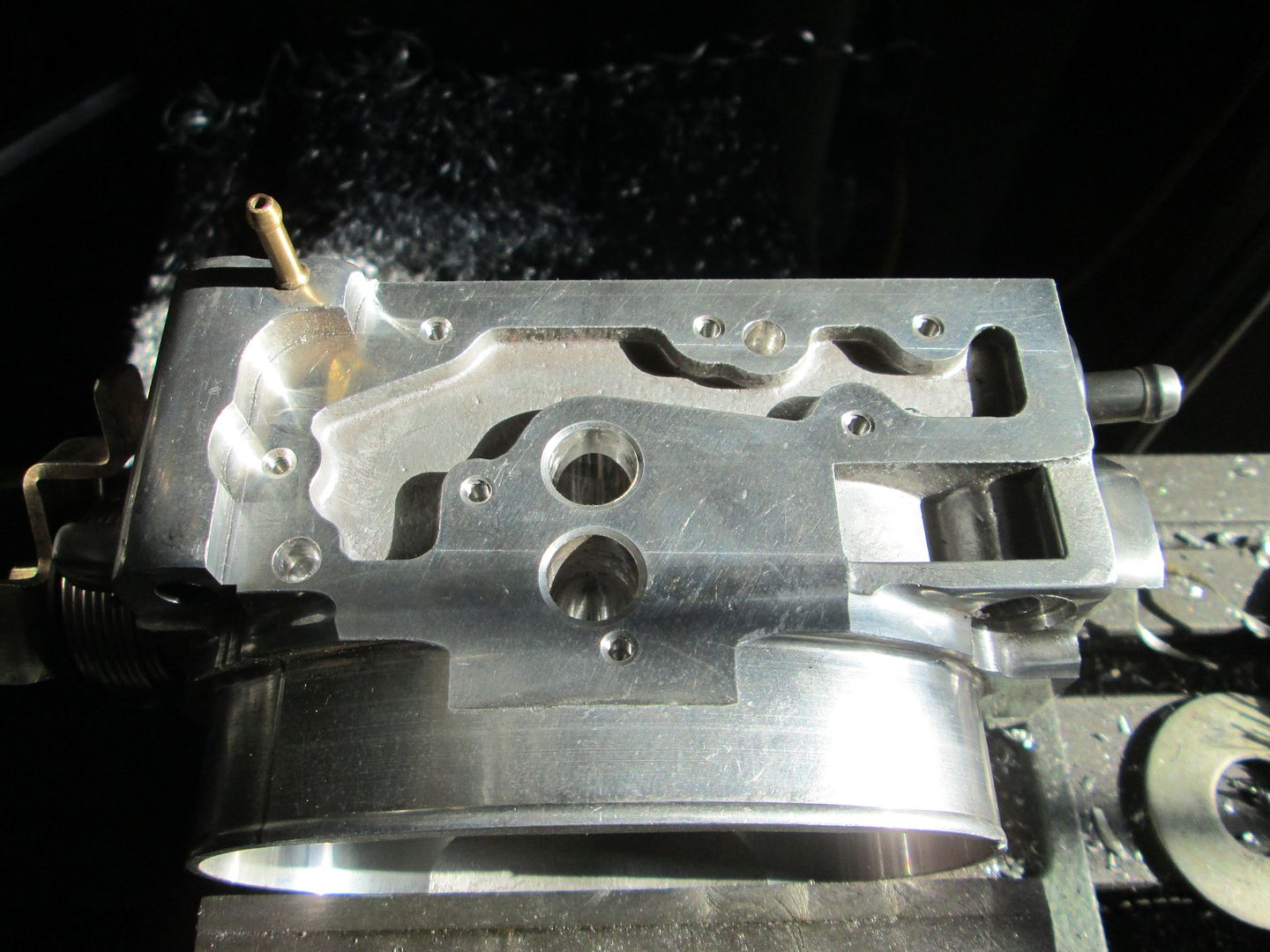
Here is an underside picture of the existing passages in the throttle body. I will need to face it down to the as cast corner so it will seal up well. Then cut a path from the port on the right to the right corner pocket. Then cut a passage from the port on the left to the existing passage on the left:
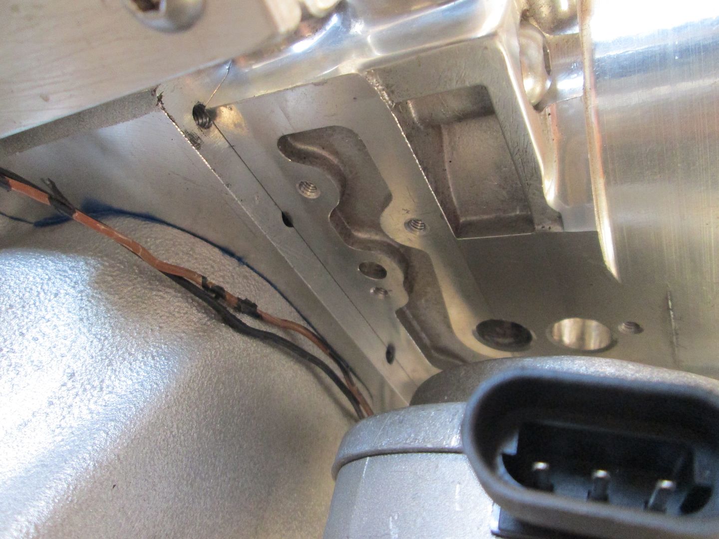
I don't like seeing wires, but sometimes there is only 1 optimal location for the sensor to go. I am referring to the engine coolant temp sensor. My philosophy is the ECM should see the hottest portion of the engine, so it can start pulling timing when needed to protect the engine. If it sees a cooler portion of the engine, it might not see the hottest cylinder and not intervene to protect it. For the SBC (and the LSx engine as well) the hottest location with a coolant port is between cylinders 8 & 6. To keep sensors and wiring minimized, I am using a 3 wire sensor that will provide the needed signal to the ECM as well as the stock fiero temp gauge. The ECM will have 100% control over the fan, so no other coolant sensor or switch is needed.
It will probably be Wednesday before I get back to Vince's car...[This message has been edited by fieroguru (edited 09-22-2013).]
|
|
|
|
bkcamaro
|
SEP 23, 05:10 AM
|
|
| quote | Originally posted by fieroguru:
Yeah, progress has been slow the last few weeks due to LS Fest and spending time on my car, working on quite a few brake kit orders, and last week we had plant dinners on all shifts on 2 days (4 crew plant) so I was working some very strange hours... However Vince's engine did get some love this weekend.
I had already installed the timing cover for the last time, made a timing notch for TDC (just to assist with positioning the cam sensor), and installed the oil pan with a new gasket:
Next I wanted to button up the valve covers, so I swapped out the roller tipped 1.52 ratio rockers with the 1.6 roller tipped rockers. With these, his roller camshaft specs are: 230/236 .576"/.570" with a 113 lobe separation (Comp Cams 280XFI HR13 part # 07-467-8). With his AFR heads flowing more at .600 than .550, he should see some additional peak HP and possibly push this thing over 400 wph (371 whp was the previous tune). Here are the 1.5 roller rockers:
Comparison pic (1.6 on the left):
Installed:
The bolts for the valve covers were about 1/4" too long to tighten the valve covers, so I shortened the 8 bolts, dumped a quart of oil over each bank and installed the valve covers. Next was to install the lower intake, I dumped 2 quarts of oil over the lifters, installed the intake gaskets, installed the intake, lined up the intake runners to the head ports (with a tunnel ram you can "see" the alignment), then torqued it down. All the ports looked like these two with just a slight portion of the lower corners of the head protruding past the ports on the HSR.
All of this work to button up the engine was to finalize the cam sensor location in the distributor housing. It took some trial and error to get the sensor lined up with the connector pointing the direction I wanted it, but eventually got there. Then the hold down clamp had to be slotted to the right position, then the original hole welded up and smoothed, the bolt hole redrilled, and a pivot stand welded to the hold down... Now the cam sensor is aligned per the EFI Connection instructions!
Hold down slotted:
Filled:
Smoothed and redrilled:
Installed:
Next I set to work on the fuel rails. They are setup for a rail mounted regulator and I am converting them to returnless, so I needed to fill the regulator port. I turned a plug with the same o-ring groove as the regulator, fabbed up an aluminum bar to span the plug and keep it secure, then trimmed the stainless steel button heads to the right length.
Bypass regulator and open port:
Turning a plug with o-ring groove:
Installed:
Capped:
Next order of business for the fuel rail was to add the fuel pressure gauge. Pretty simple with the 1/8 NPT elbow, but when it was tight, the inner portion of the threads were partially blocking the port, so I drilled down through the fitting to clearance the part the protruded into the opening.
Threads protruding:
Clearanced:
Then purged all the fuel rails and fittings with brake clean to remove any debris, installed the injectors (36# Bosch) and started playing around with wiring options to hide the connectors. Originally I didn't think there was any chance of flipping the connectors to the back side, but it works!
I am in the process of filling all the extra coolant ports and vacuum ports with chrome plugs. This picture also shows the coolant fill and the -16 AN fitting.
Here is the other -16AN elbow and a steel weld end, there wont be much length to the braided stainless steel hose... I will weld the steel end to some 1" schedule 40 pipe that will be the coolant crossover to the passenger side.
Here is a mockup of the 1 3/4" header flange to the exhaust ports on the heads (I have sense removed the stock fiero temp sender and capped that coolant port):
I think I also figured out a slick/relatively simple solution for the IAC housing that will not fit in the stock location. I plan to machine a 1/4" plate to cap off the complete underside of the throttle body housing and extend it out past the TPS side of the throttle body as needed. Then I will use and modify the existing passages under the throttle body (and machine some in the 1/4" plate), to create the air flow path to the new IAC position, which will be 90 degrees from the stock position and off to the side of the throttle body. This pic shows the new position for the IAC housing and the available room for a 1/2" plate:
Here is a pic of the ports on the IAC housing:
Here is an underside picture of the existing passages in the throttle body. I will need to face it down to the as cast corner so it will seal up well. Then cut a path from the port on the right to the right corner pocket. Then cut a passage from the port on the left to the existing passage on the left:
I don't like seeing wires, but sometimes there is only 1 optimal location for the sensor to go. I am referring to the engine coolant temp sensor. My philosophy is the ECM should see the hottest portion of the engine, so it can start pulling timing when needed to protect the engine. If it sees a cooler portion of the engine, it might not see the hottest cylinder and not intervene to protect it. For the SBC (and the LSx engine as well) the hottest location with a coolant port is between cylinders 8 & 6. To keep sensors and wiring minimized, I am using a 3 wire sensor that will provide the needed signal to the ECM as well as the stock fiero temp gauge. The ECM will have 100% control over the fan, so no other coolant sensor or switch is needed.
It will probably be Wednesday before I get back to Vince's car...
|
|
i am not going to lie but i am extremely jealous  
|
|
|
|
Trinten
|
SEP 23, 07:07 AM
|
|
Yeah, he does awesome work.
|
|
|
|
CowsPatoot
|
SEP 23, 11:38 AM
|
|
| quote | Originally posted by bkcamaro:
i am not going to lie but i am extremely jealous |
|
You aren't the only one.
|
|
|
|
Raydar
|
SEP 23, 12:42 PM
|
|
| quote | Originally posted by CowsPatoot:
You aren't the only one. |
|
...next in the "jealous" line...
|
|
|
|
carbon
|
SEP 23, 01:08 PM
|
|
|
|
|
Jncomutt
|
SEP 23, 06:11 PM
|
|
|
Ugh, I agree, pet peeve of mine,especially cause I'm usually reading the forum on my phone.
|
|
|
|
fieroguru
|
SEP 25, 08:25 PM
|
|
Did a little work on the remote IAC....
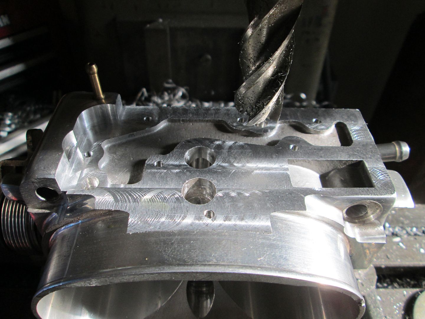
Set the throttle body up on the mill:
Milling the bottom surface flat, then the slots from the IAC ports to the edge:
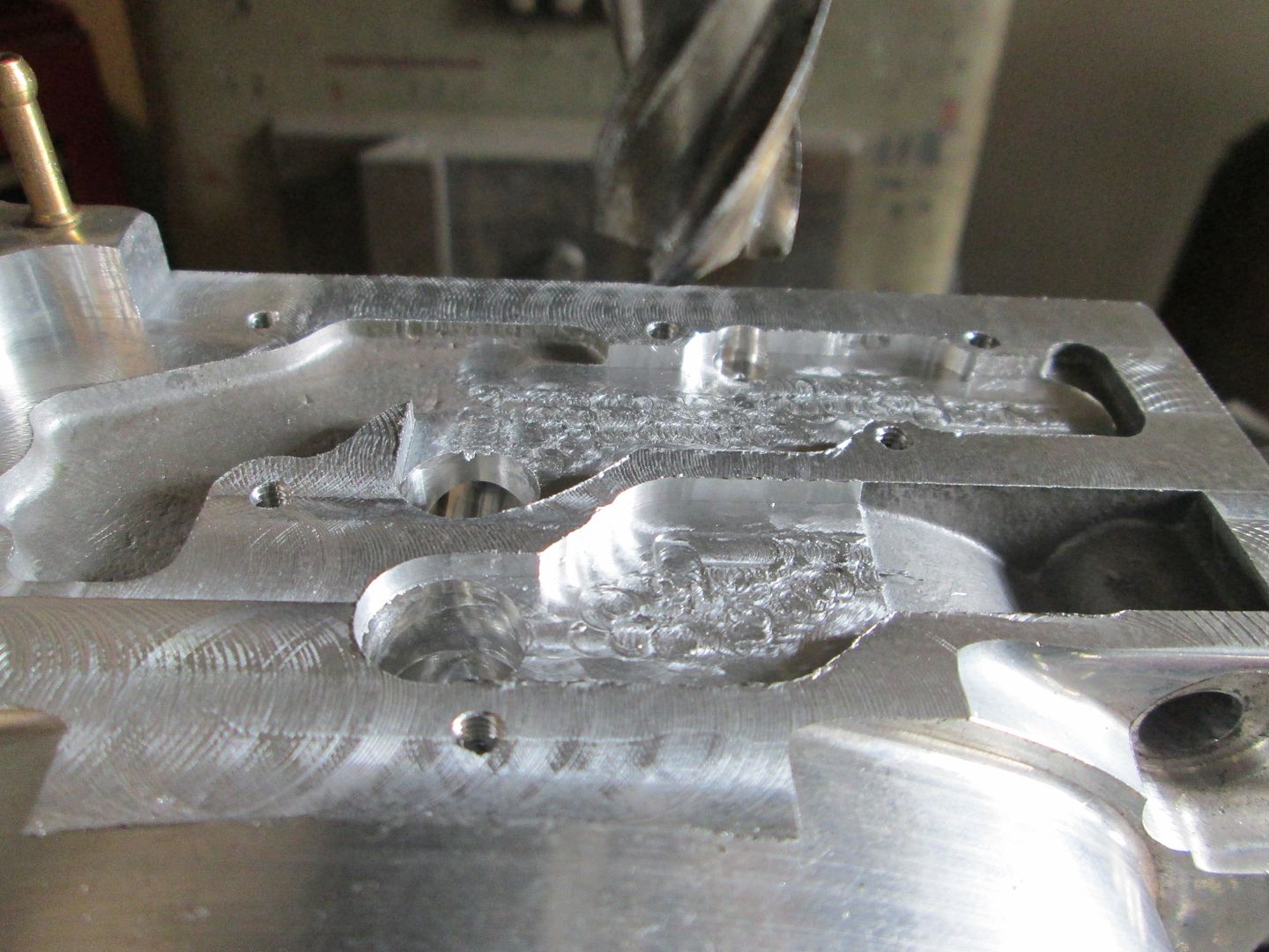
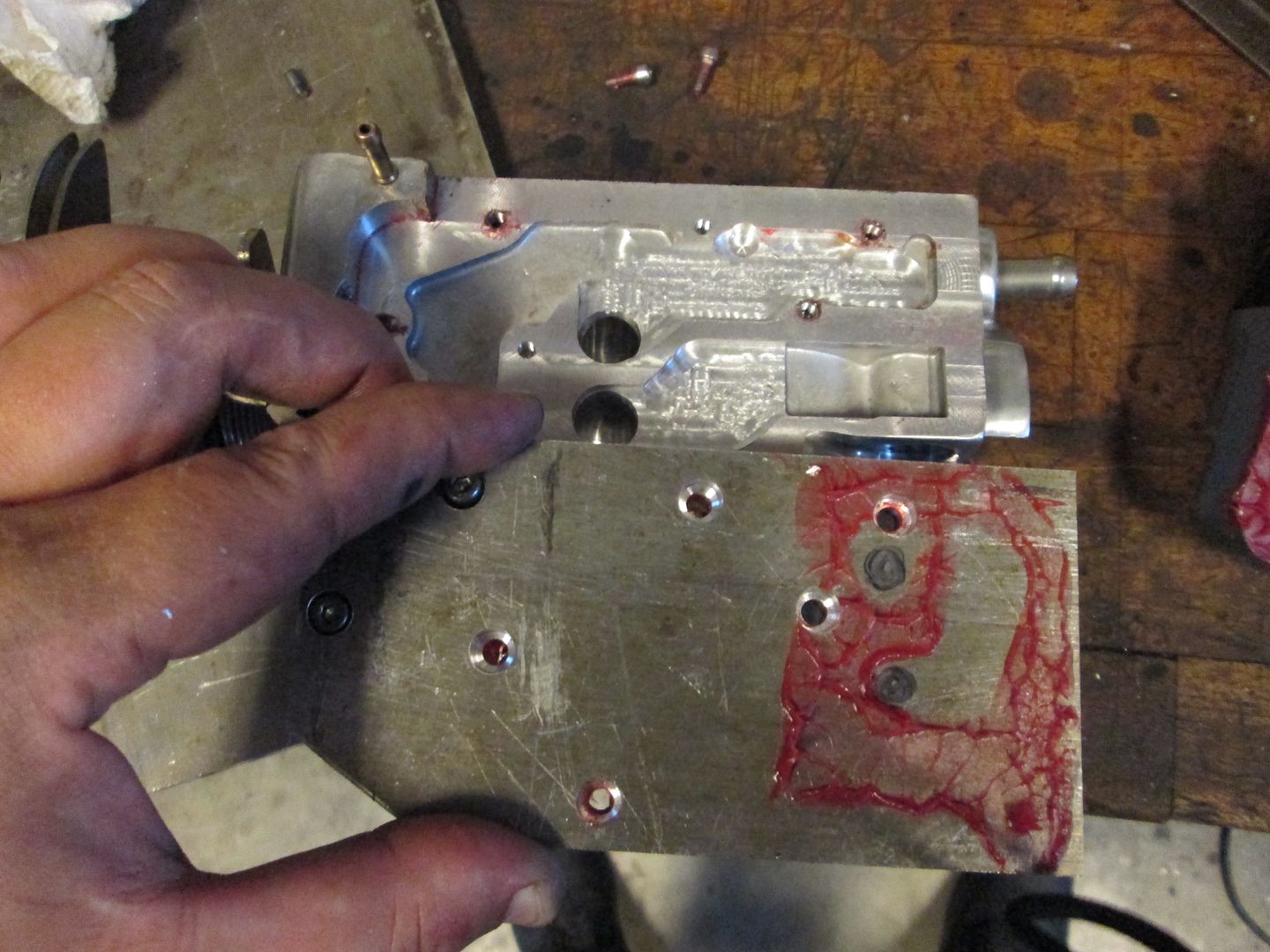
Here I used a marker to show the flange area and the new air passages:
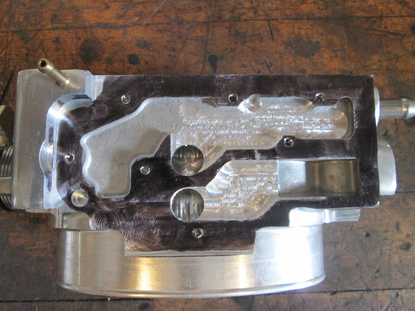
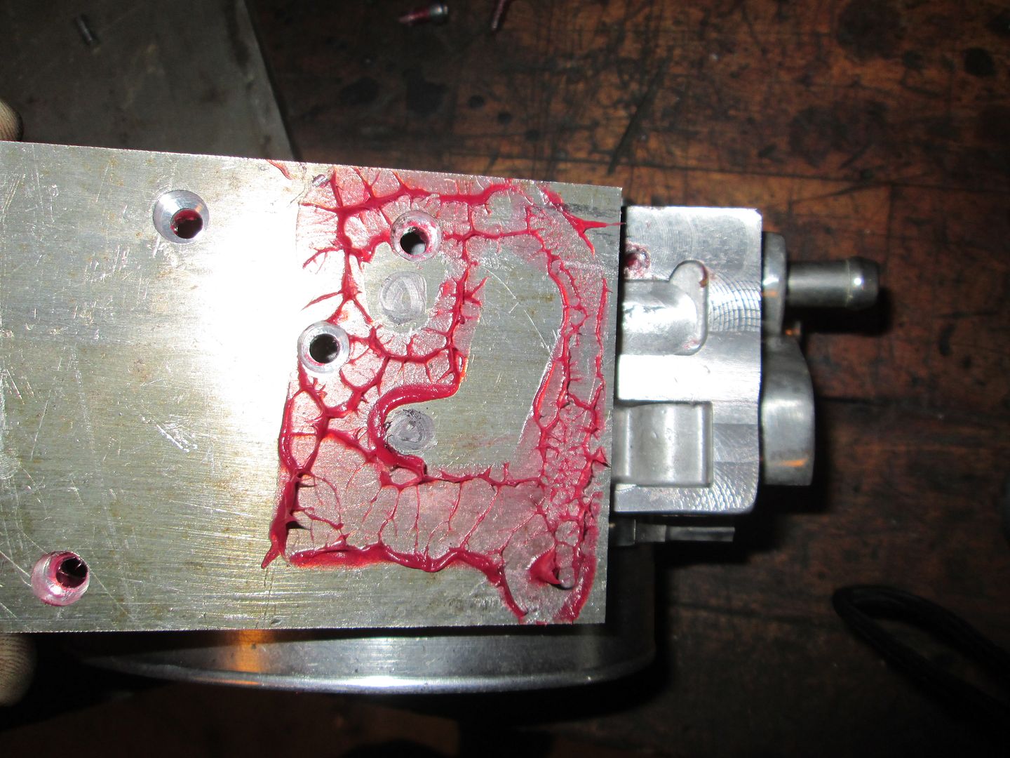
Then I cut out a piece of 3/8" aluminum plate, cut it to shape, located and drilled all the bolt holes. Then used some grease to transfer the port pattern from the throttle body.
Then milled the passages in the aluminum plate:
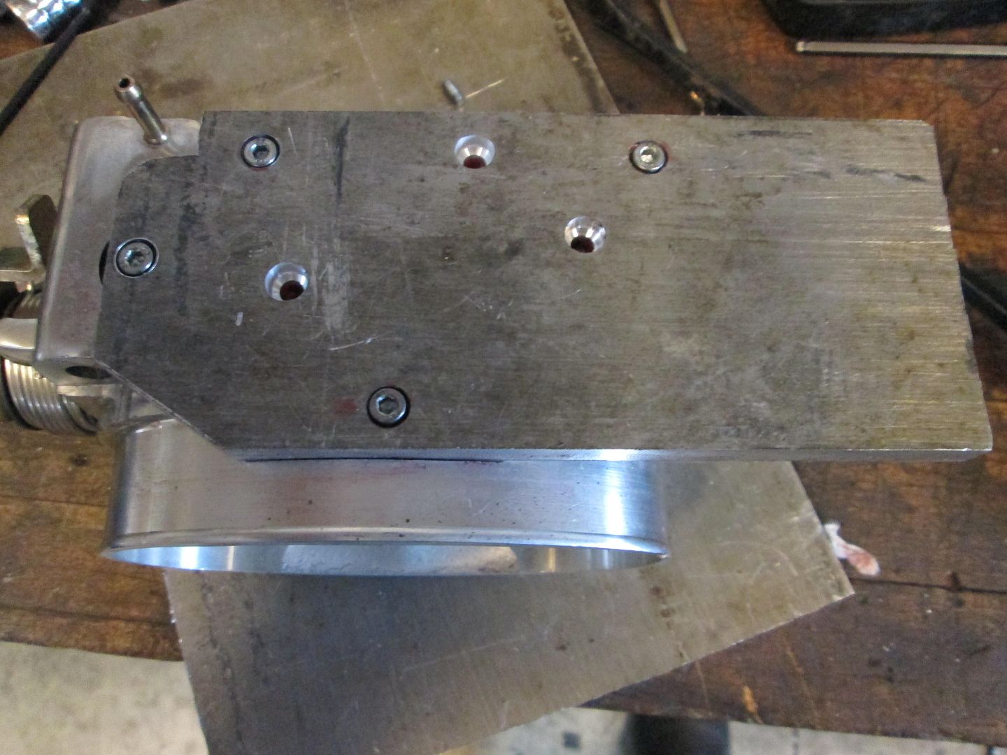
Then I trimmed the side to clear the fuel rail and checked everything for clearance:
Here is where the IAC will be on the underside. I do need to mill the plate or the IAC housing to get more clearance to the connector on the distributor:
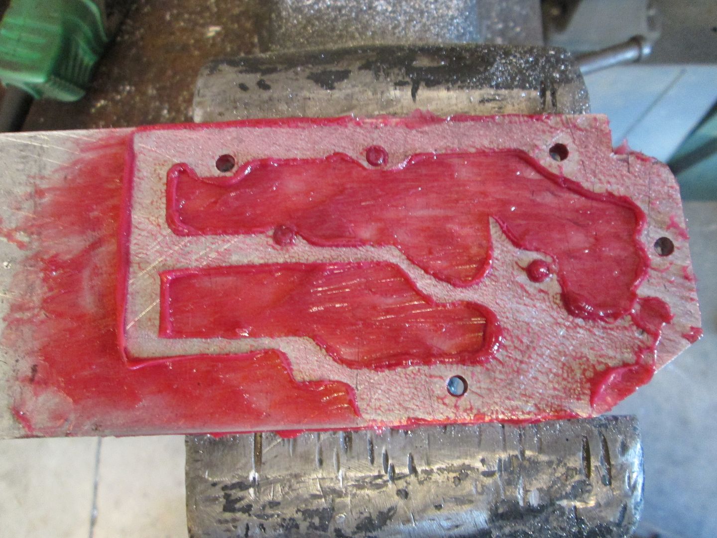
I used the grease (and black marker) to show the port locations in the IAC and how they line up with the passages in the bottom of the throttle body:
I still need to drill/tap the mounting holes in the plate for the IAC, drill the plate and tap the throttle body for another bolt in the far corner, then either mill the IAC housing or the plate for more connector clearance... then I can move on to the next challenge.
|
|
|
|
 But why quote the whole long post, just to say it?
  It kinda muddies the thread when a post with 25-30 pictures is quoted in full...