
 
     |
| Trinten's SBC/F23 build - The work has begun! (Page 14/76) |

|
fieroguru
|
AUG 15, 06:33 AM
|
|
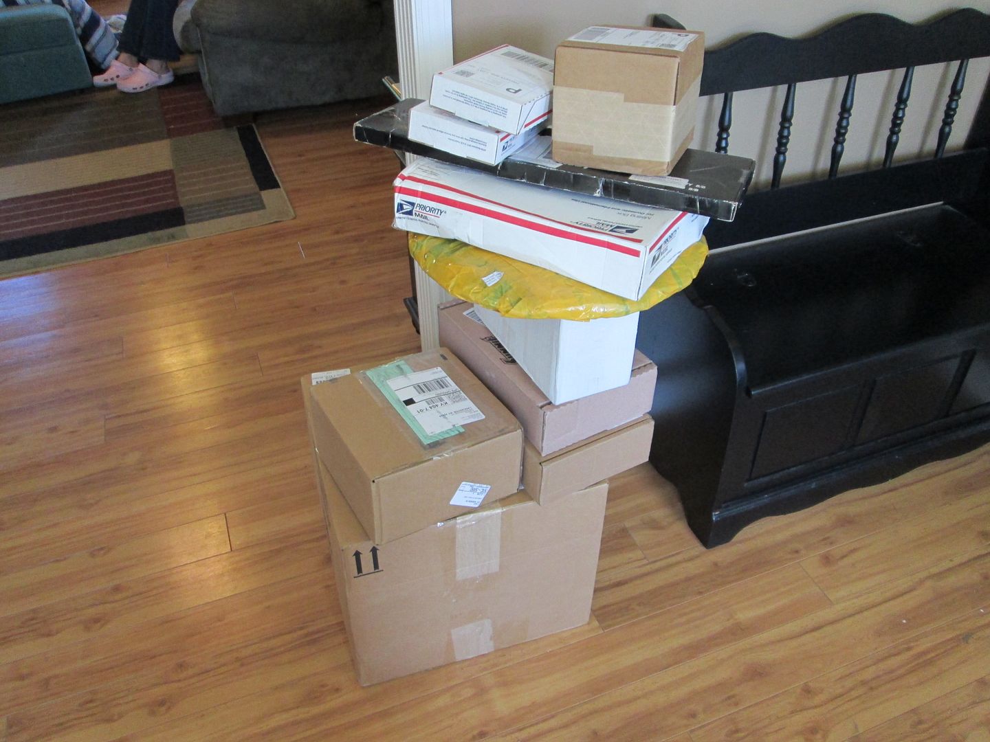
My wife said it was Carsmas yesterday:
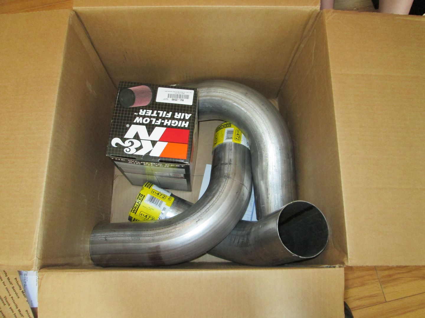
Here are the main parts for the 4" cold air intake:
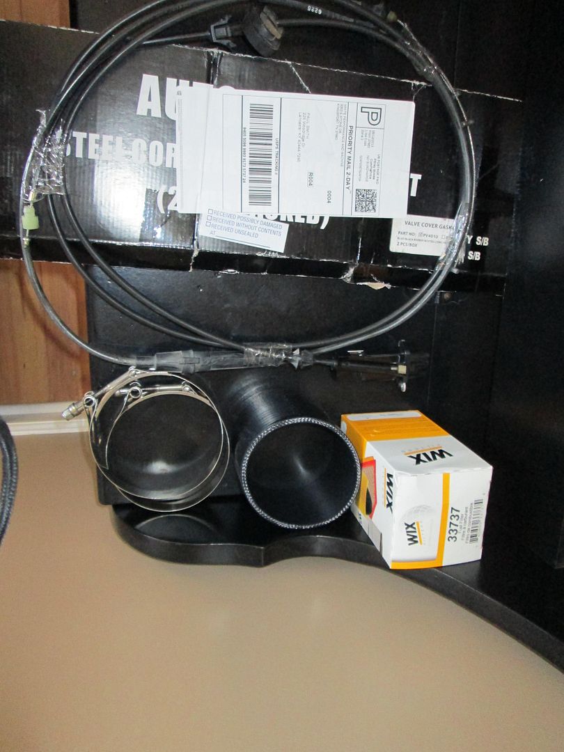
The silicone coupler, T bolt clamps, 88 4cyl throttle cable, fuel filter, and valve cover gaskets:
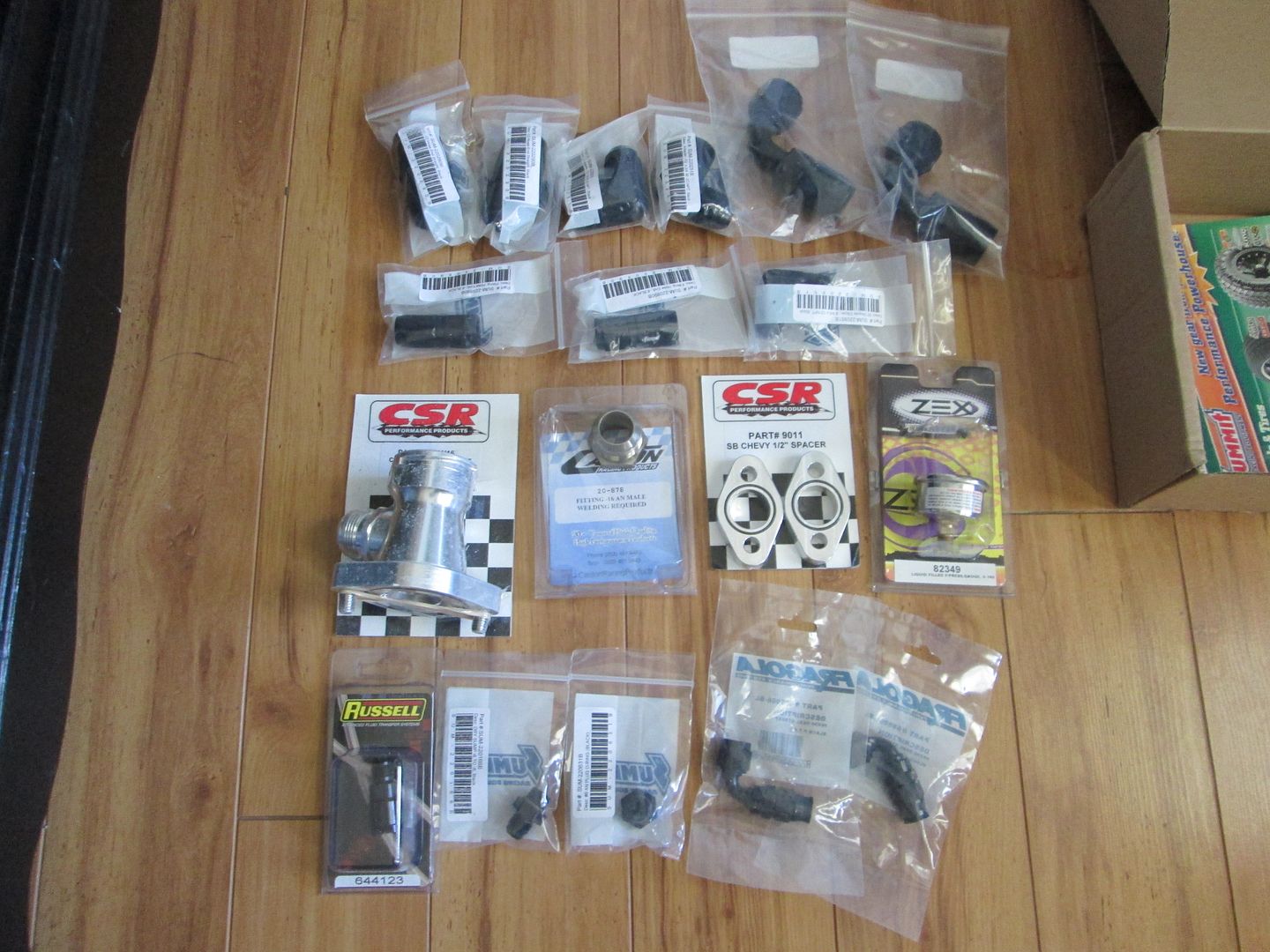
Many of the AN parts - a few are still in route:
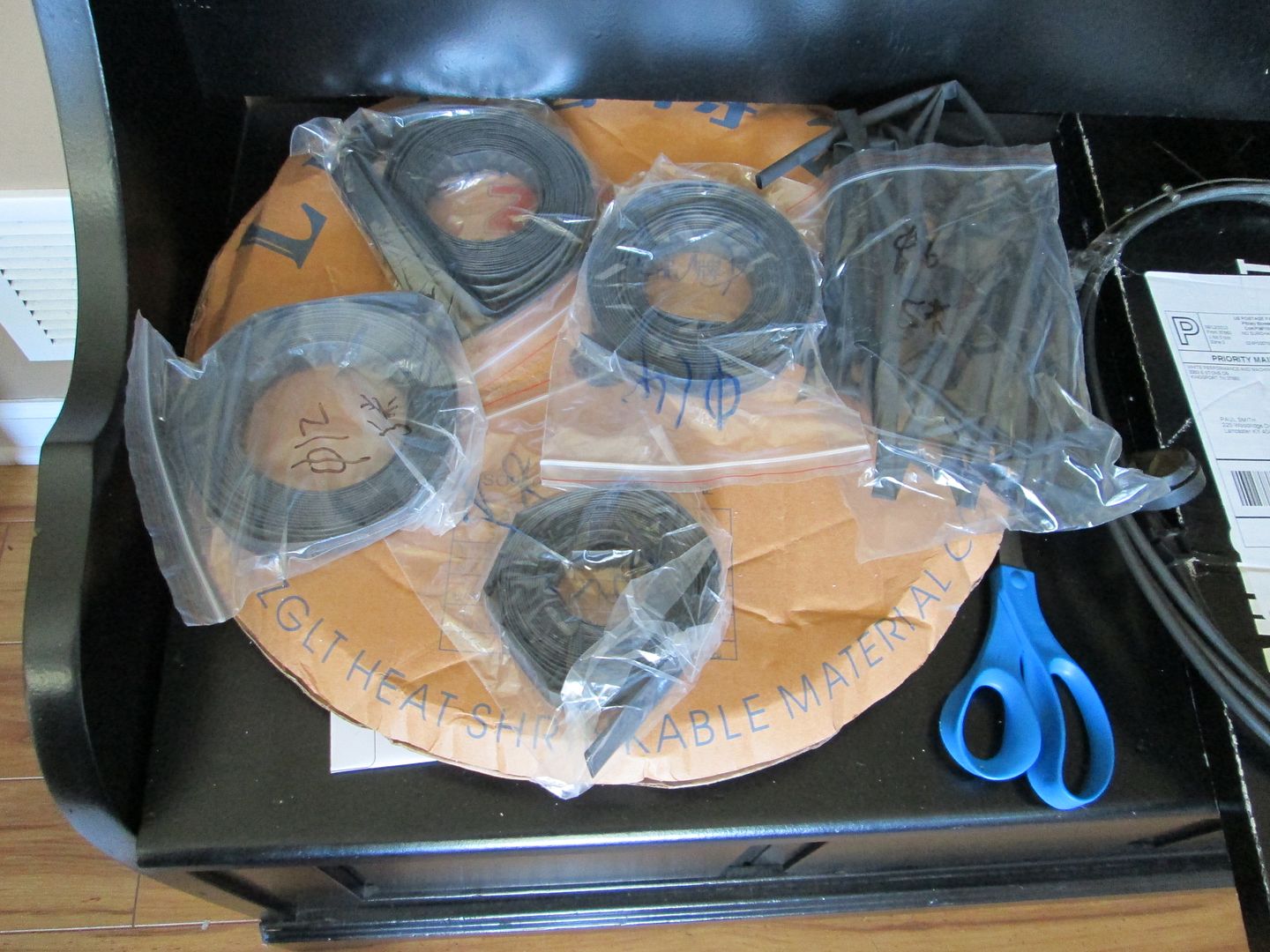
Heat shrink for the harness - this stuff came all the way from China!
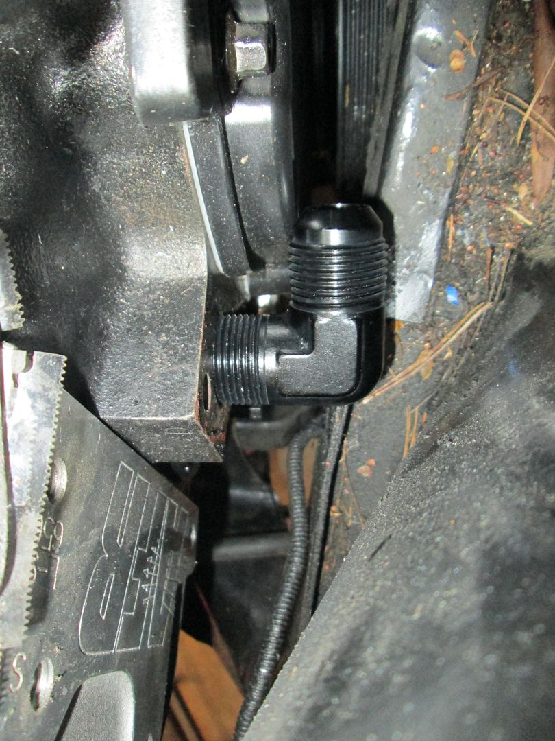
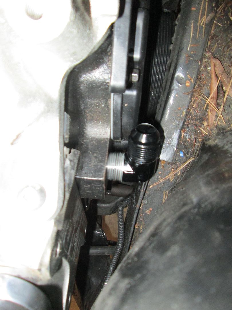
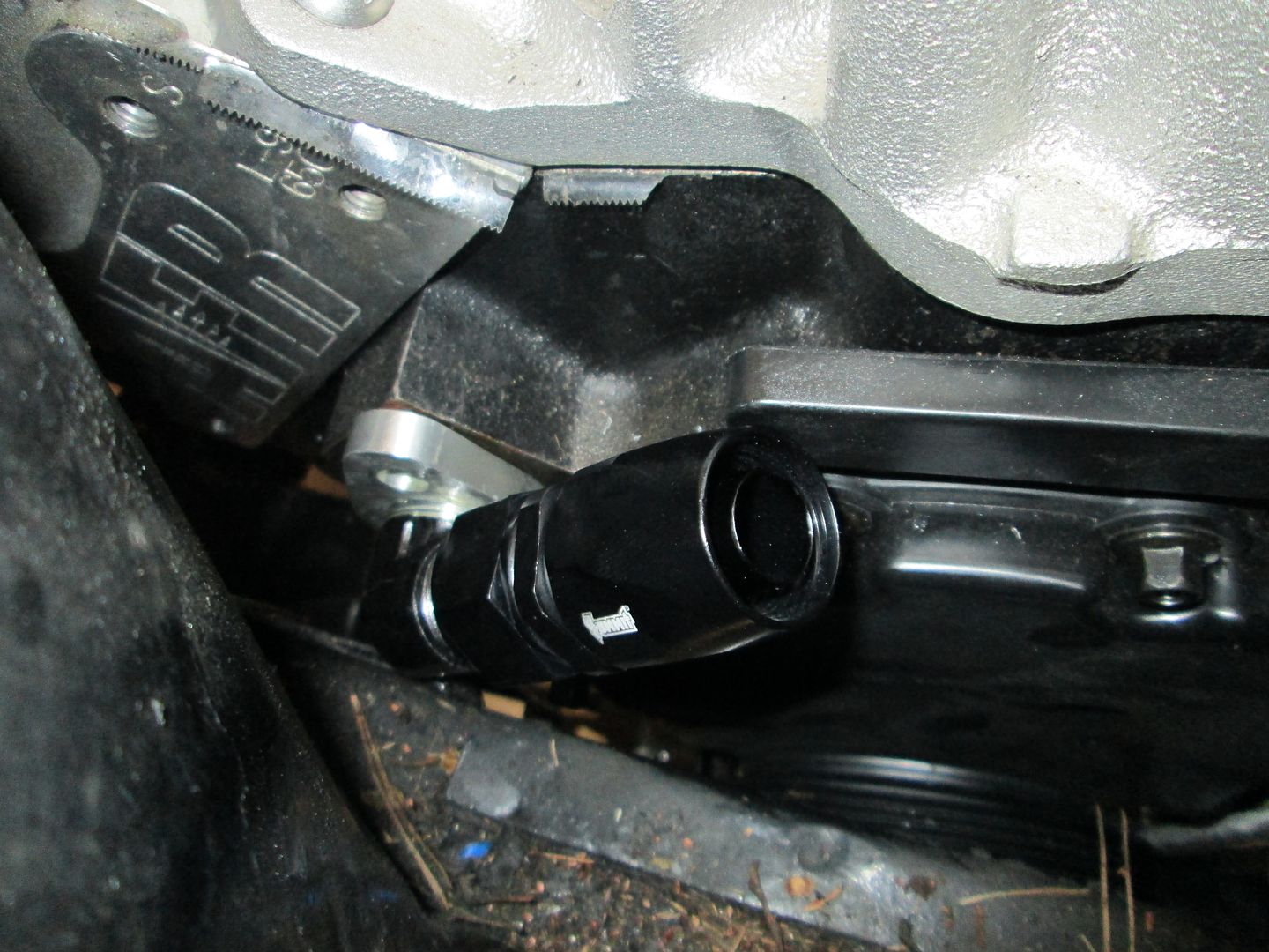
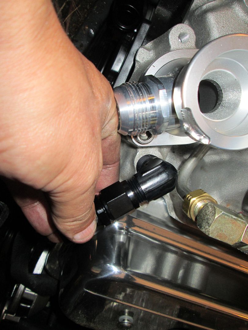
Then I went to work on the mods needed for the coolant hoses at the block. Here is one of the fittings and it clearly needs to be shorter if it is to clear the frame rail:
So I trim the threaded end down and then use a pipe die to extend the threads on the fitting:
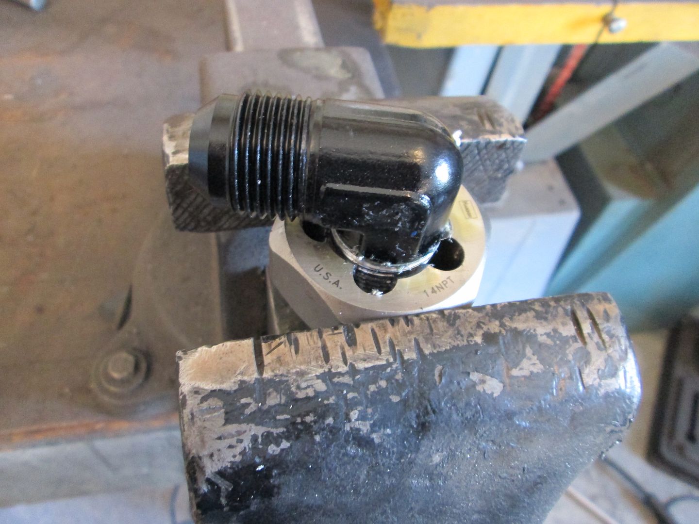
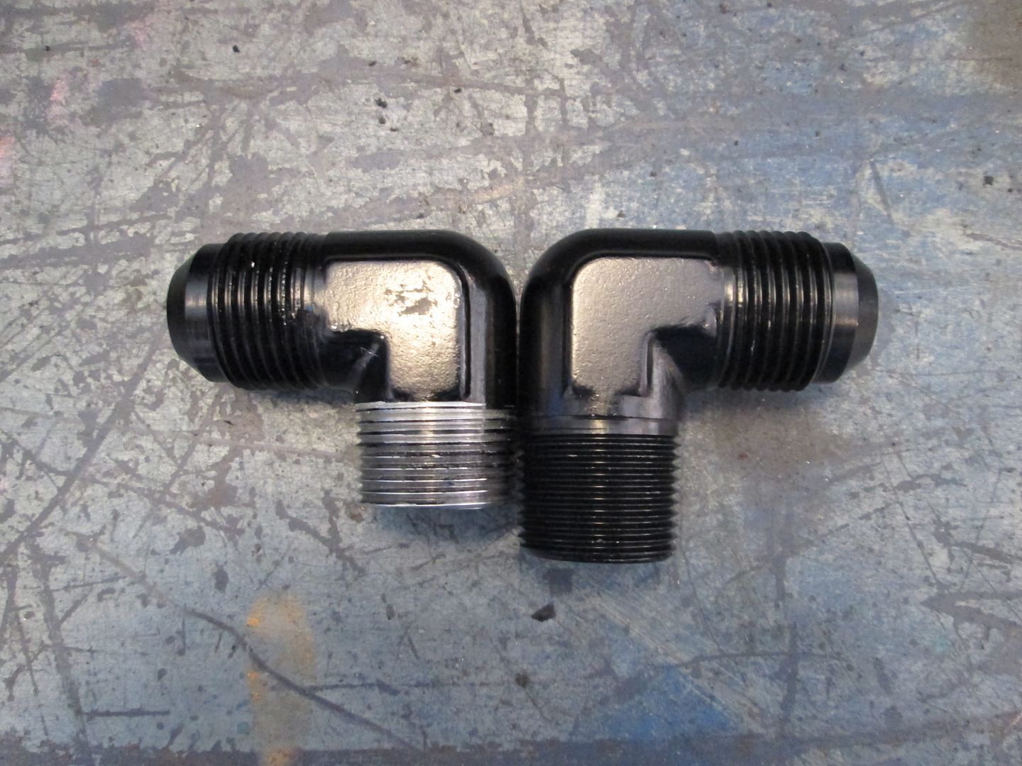
Its getting closer, just needs to be a little shorter:
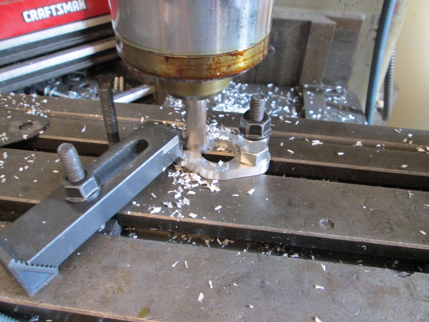
The fitting above will thread into some aluminum plates (water pump spacers), but one of them also needs modified to make it much thinner. So it spends some time on the mill:
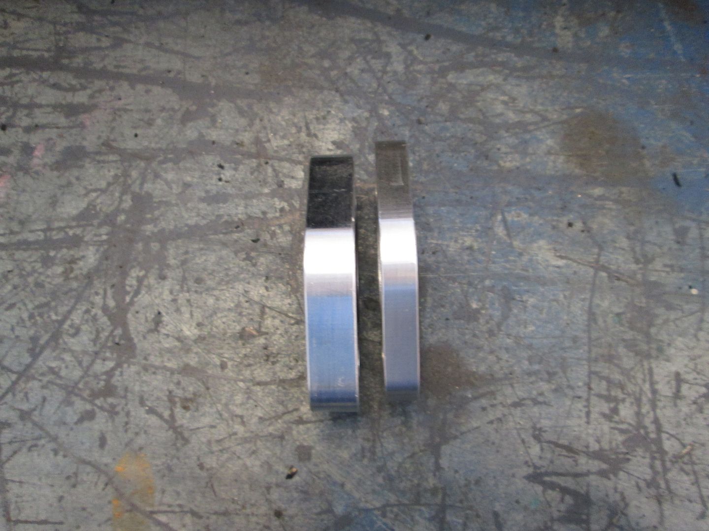
Comparison between the two now:
Tap the center hole for the fitting:
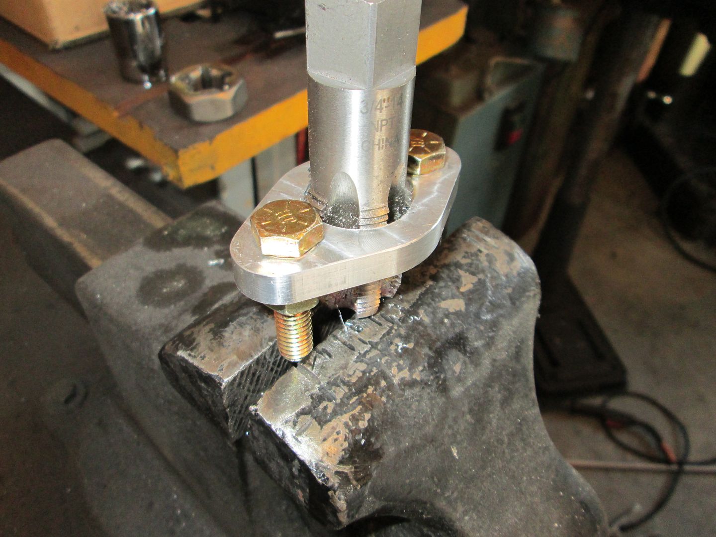
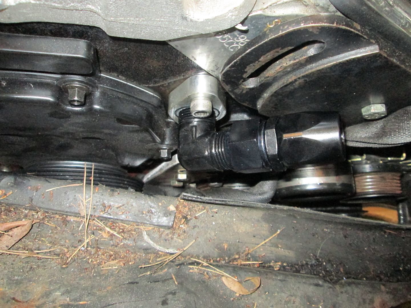
Here the modified fitting is sitting in place with the hose end attached:
The other one fits with only having to thread the plate:
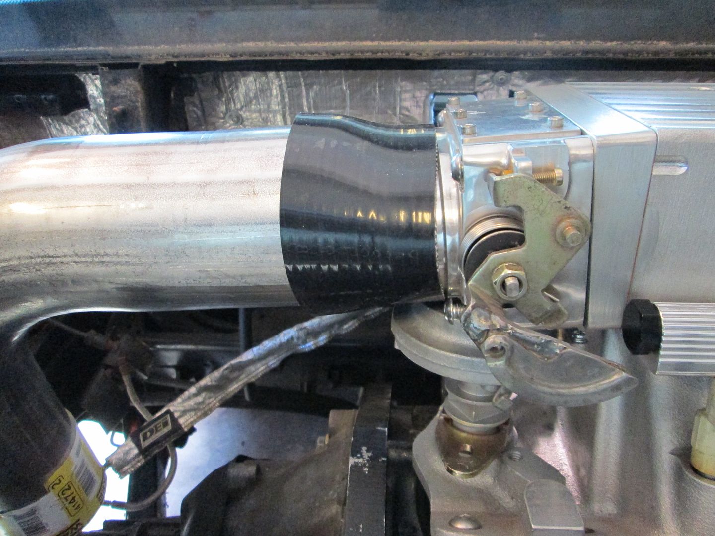
Here is a mockup of the cold air intake. I will likely oval the tube so the round to oval transition happens in the tube and not the coupler:
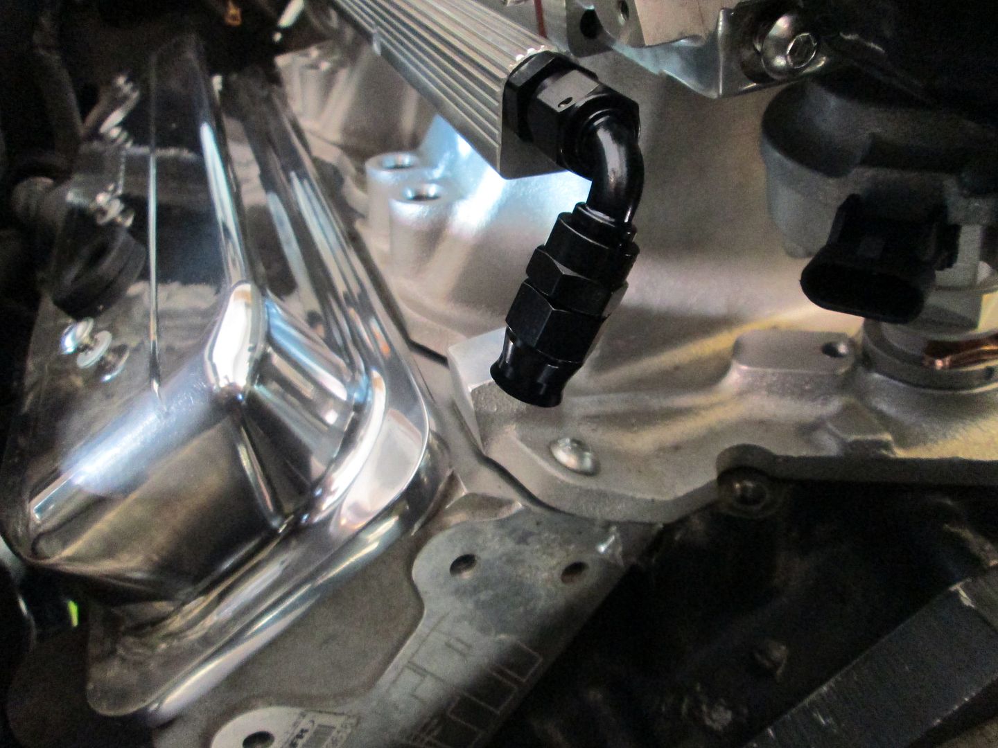
Fuel line fitting:
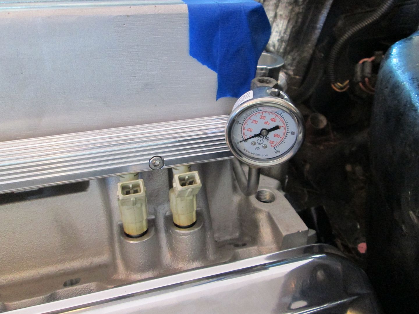
Fuel pressure gauge:
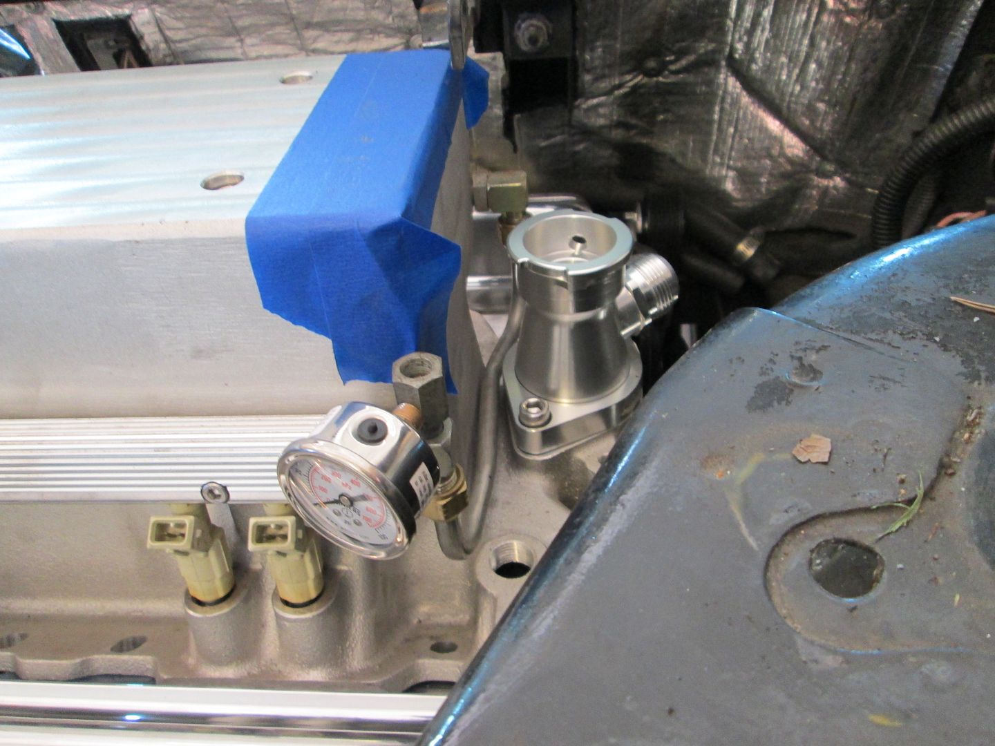
Themostat housing:
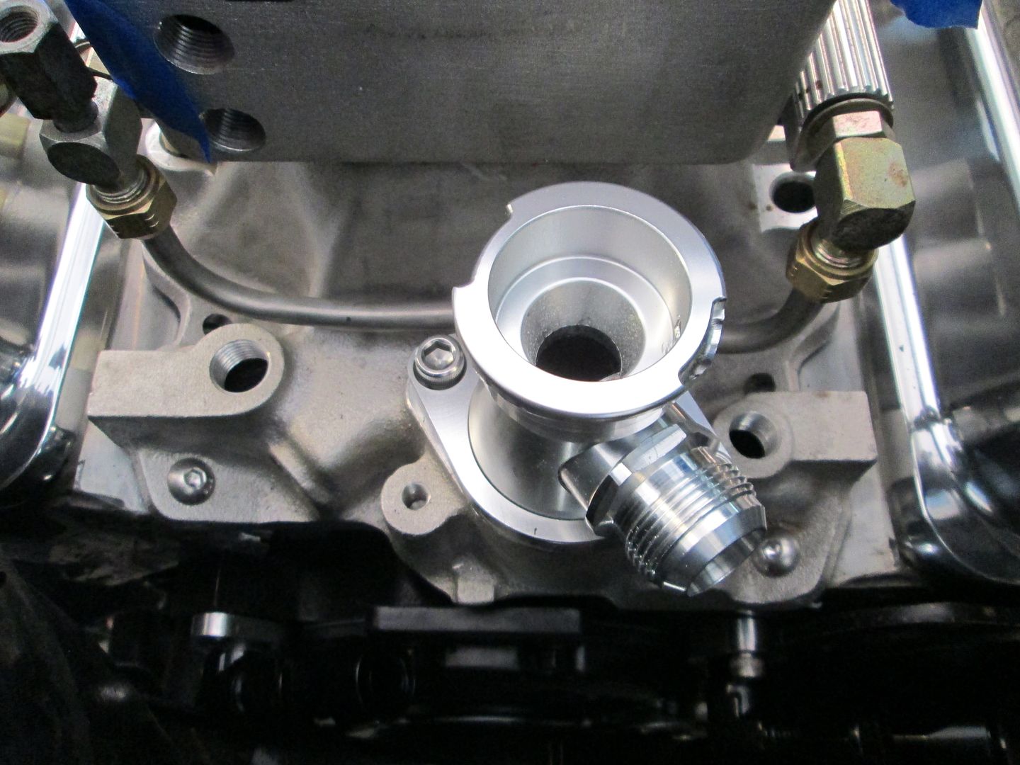
The heater hose will either come out here (after I drill/tap a hole):
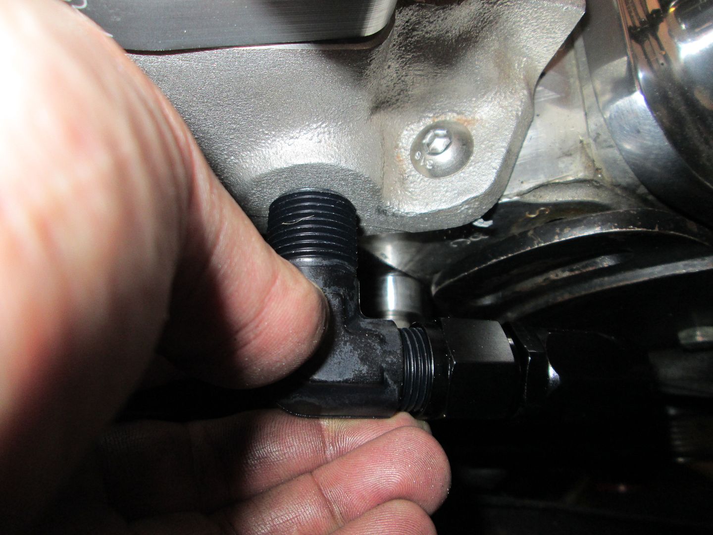
Or here if I get a smaller fitting (to use the existing hole):
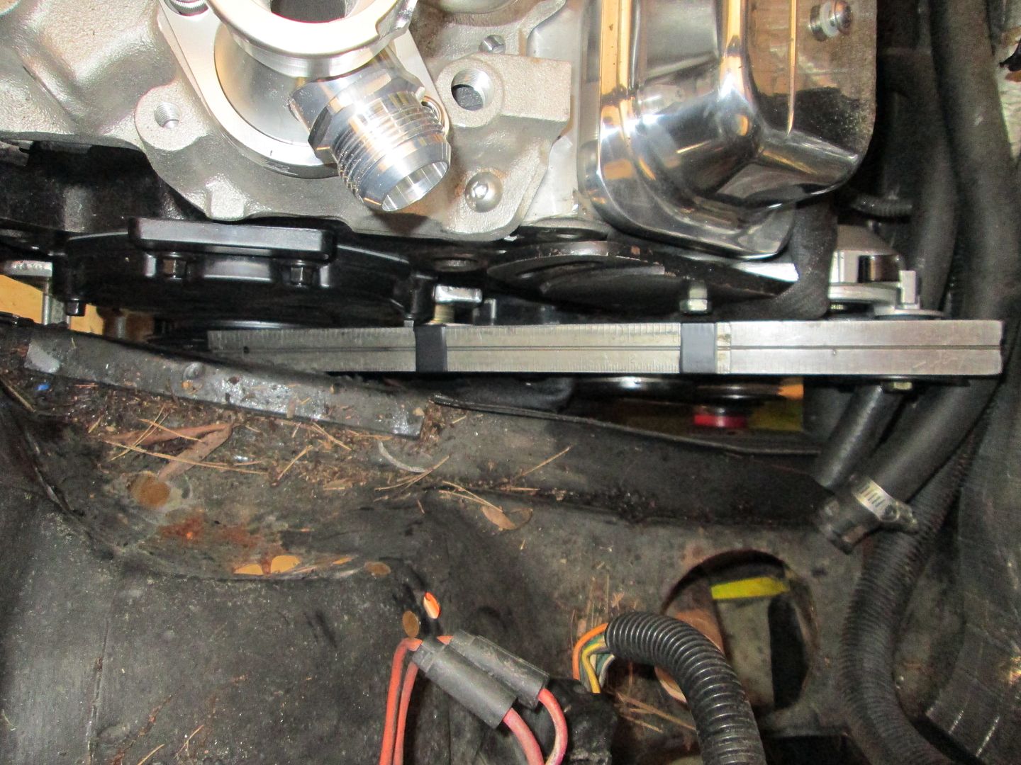
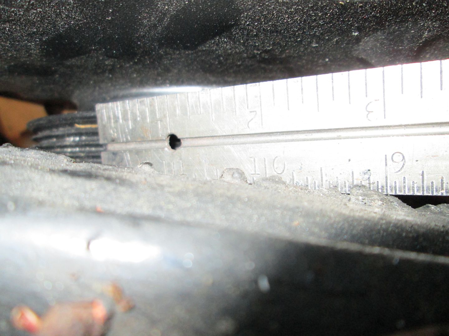
Mockup of the belt clearance... I will need to notch the current notch some (it doesn't go high enough to clear the angled belt:
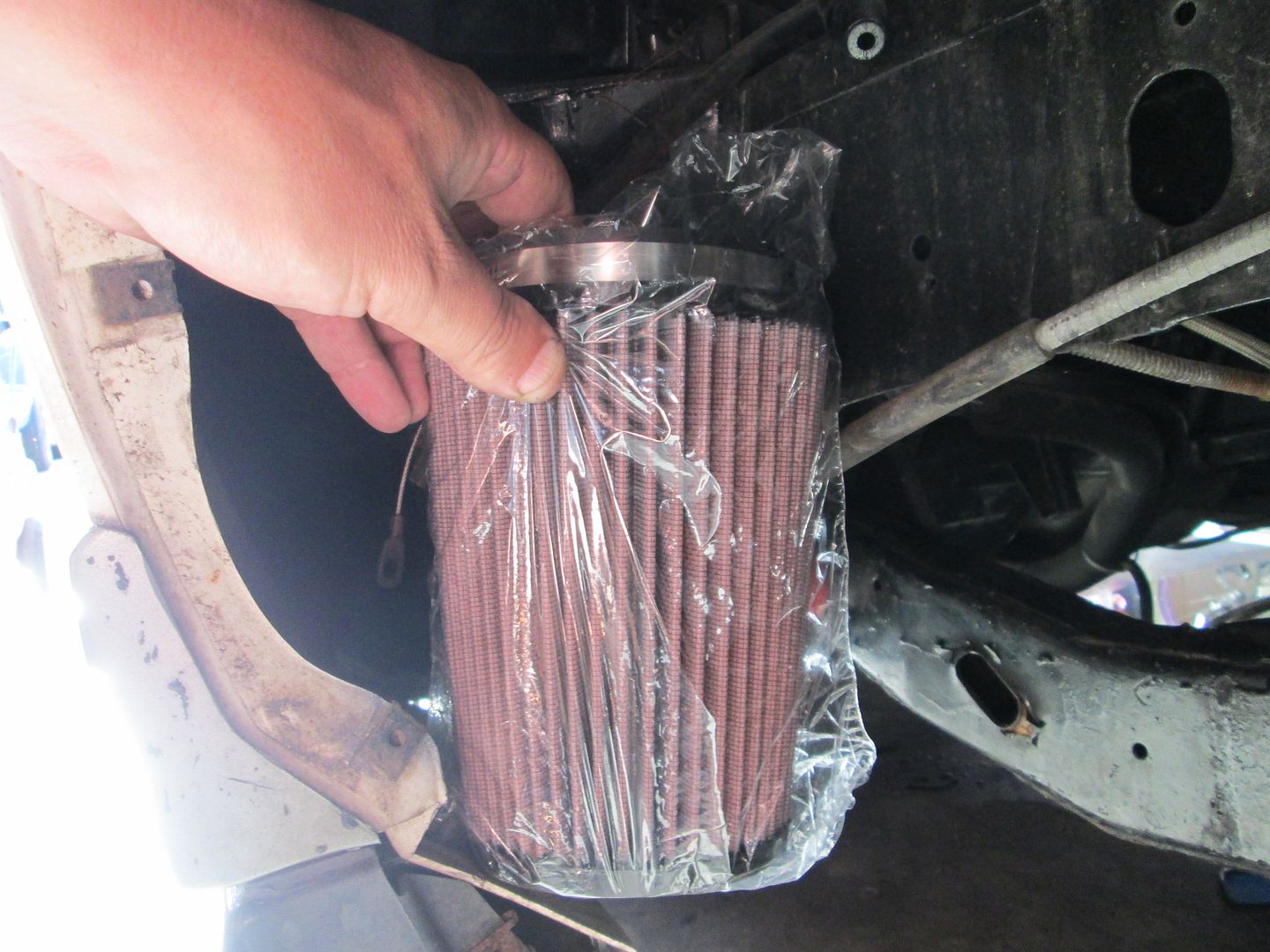
Here is the air filter and its approximate home:
|
|
|
|
fieroguru
|
AUG 17, 07:02 PM
|
|
Finished the preliminary engine placement tests today. Removed the spring and put the upright/strut back into position and raised it till the strut bottomed out or it hit something. Good news is that on both sides while clearance is very tight, the strut bottoms out before the lower a-arms make contact with the transmission or the front engine mount.
Fully compressed:
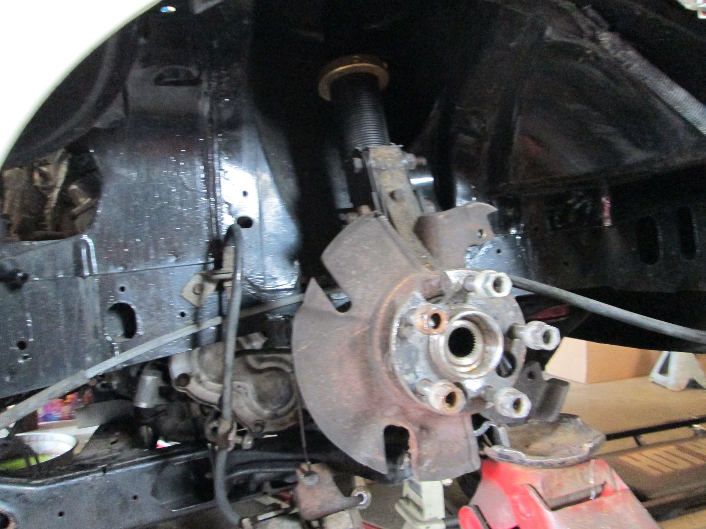
Very small gap between the transmission and the a-arm:
Pretty much the same gap on the passenger side as well (I was able to pass a piece of paper through the gap):

I scribed the location of the mounts on the cradle, so I could replicate the placement. Then it was time to remove the drivetrain and get it back on the fixture. Used the marks to position it and made sure it was square and level in both directions. Once that was done, I started working on the front transmission mount.
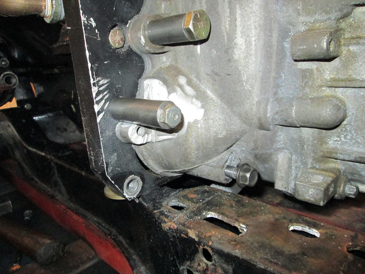
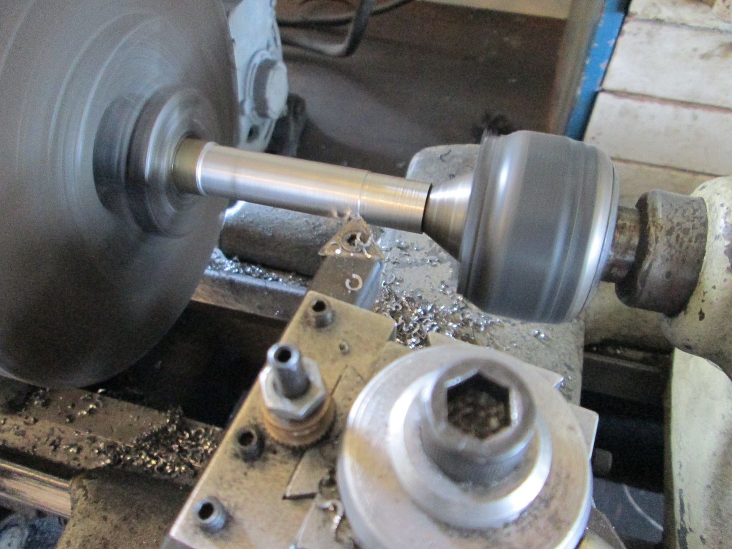
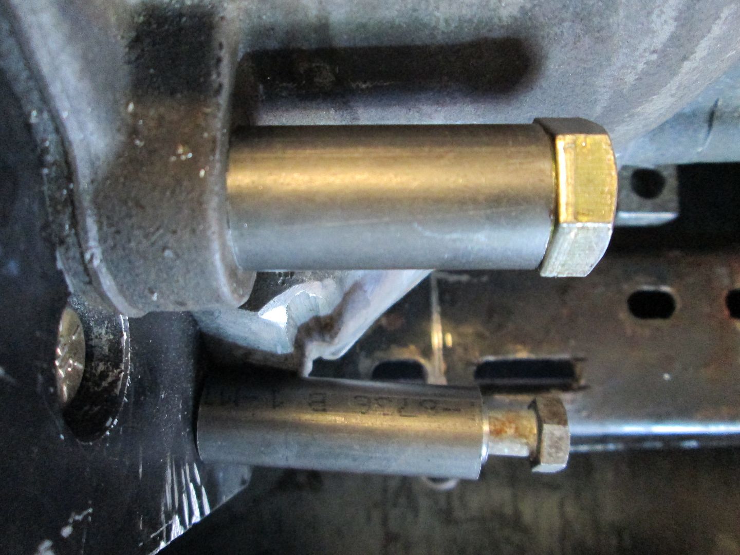
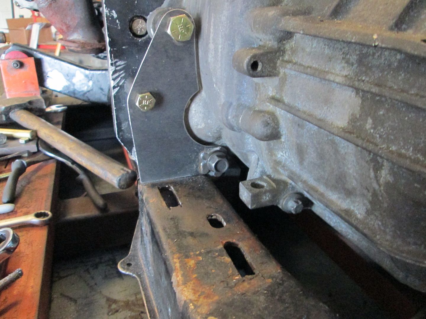
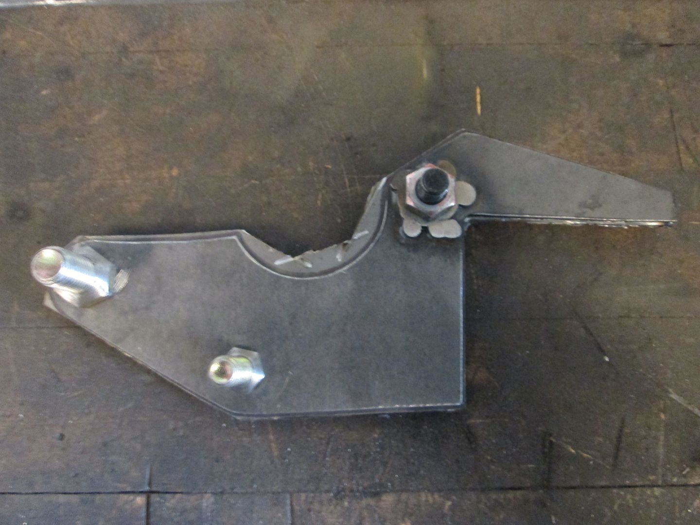
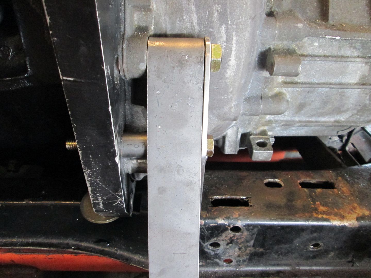
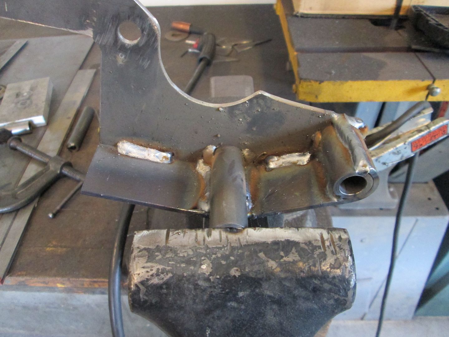
I like to use a minimum of 3 bolt holes for my mounts and decided to use these 3 holes. One is a transmission hole, one is the top starter hole on the Archie adapter plate and the last hole is a bellhousing bolt hole. None of the holes are in the same plane, so I made some spacers from 3/4" tube with 1/8" wall. This is a good fit for the upper bellhousing bolt (now 1/2"), but the started bolt is 3/8" so I turned down a sleeve for an aftermarket sway bar link for a bushing:

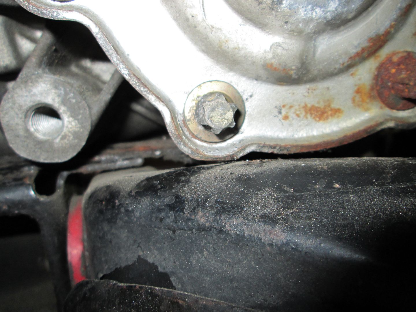
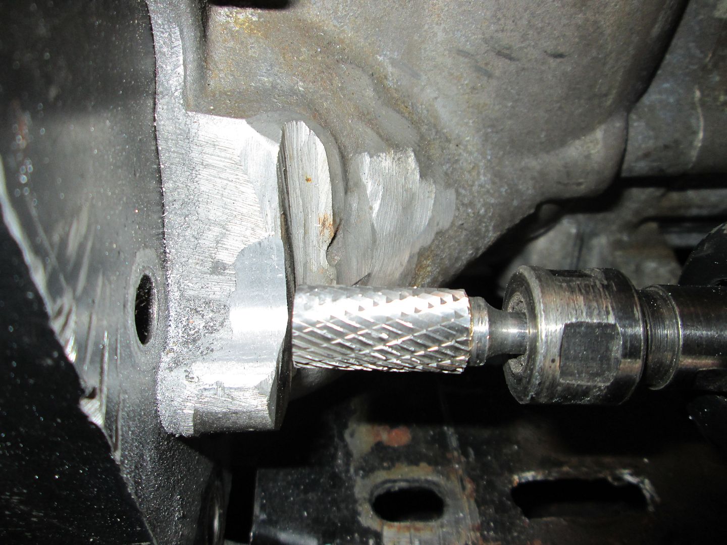
Before the starter bolt spacer could be installed, I had to clearance the transmission slightly with my die grinder. This area had been previously clearanced by someone else... I only did the smooth shiny part. This area will be covered by the mount so it will be hidden from view:
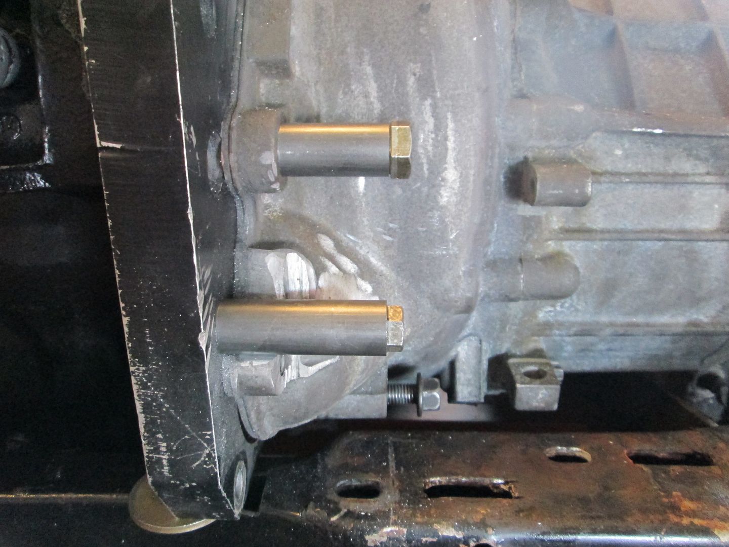
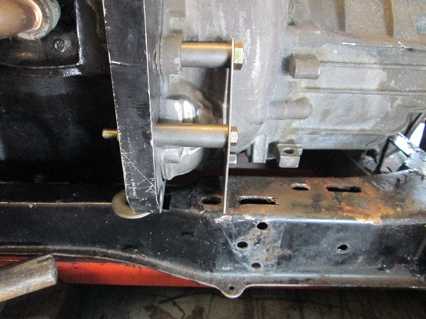
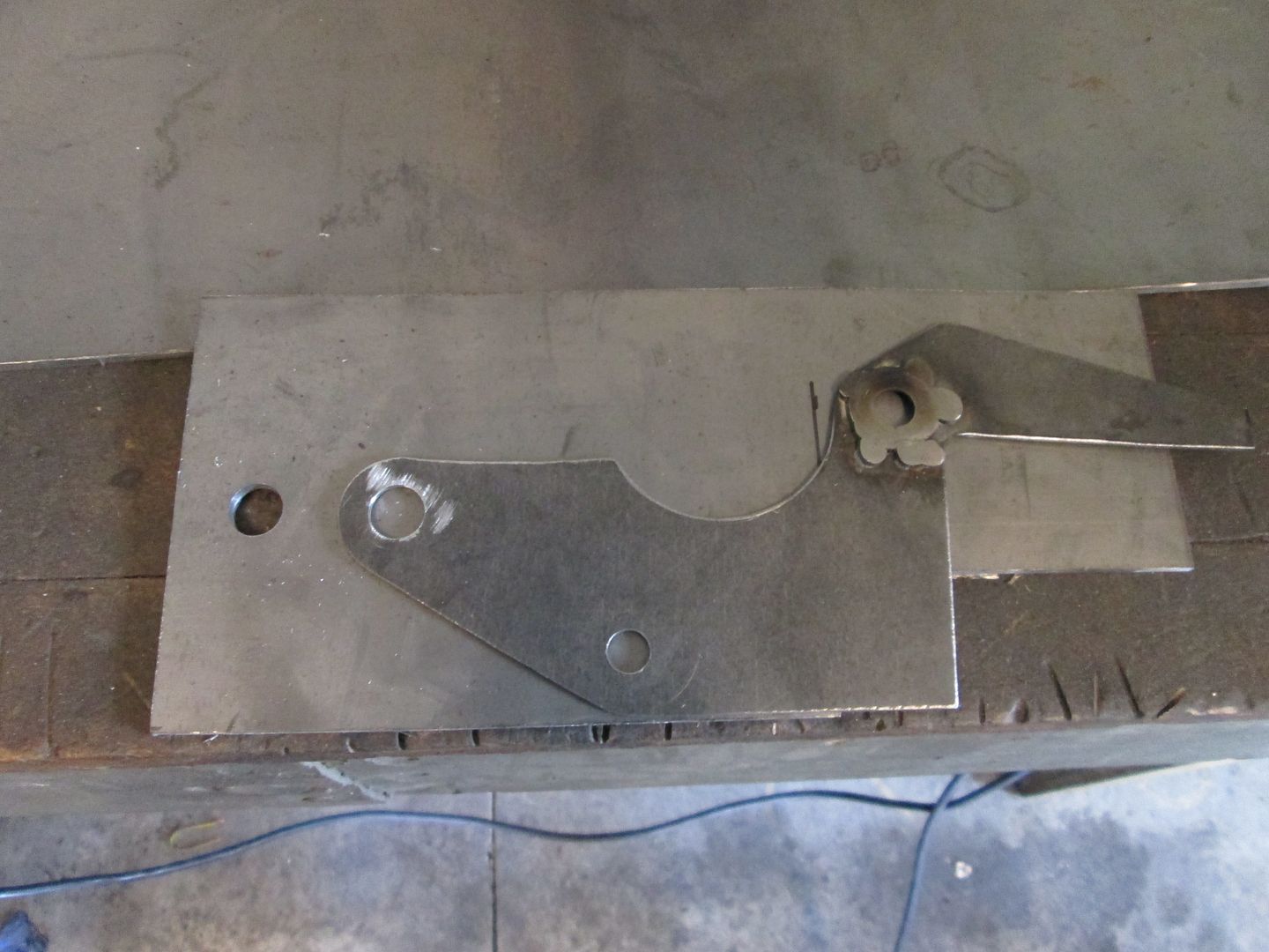
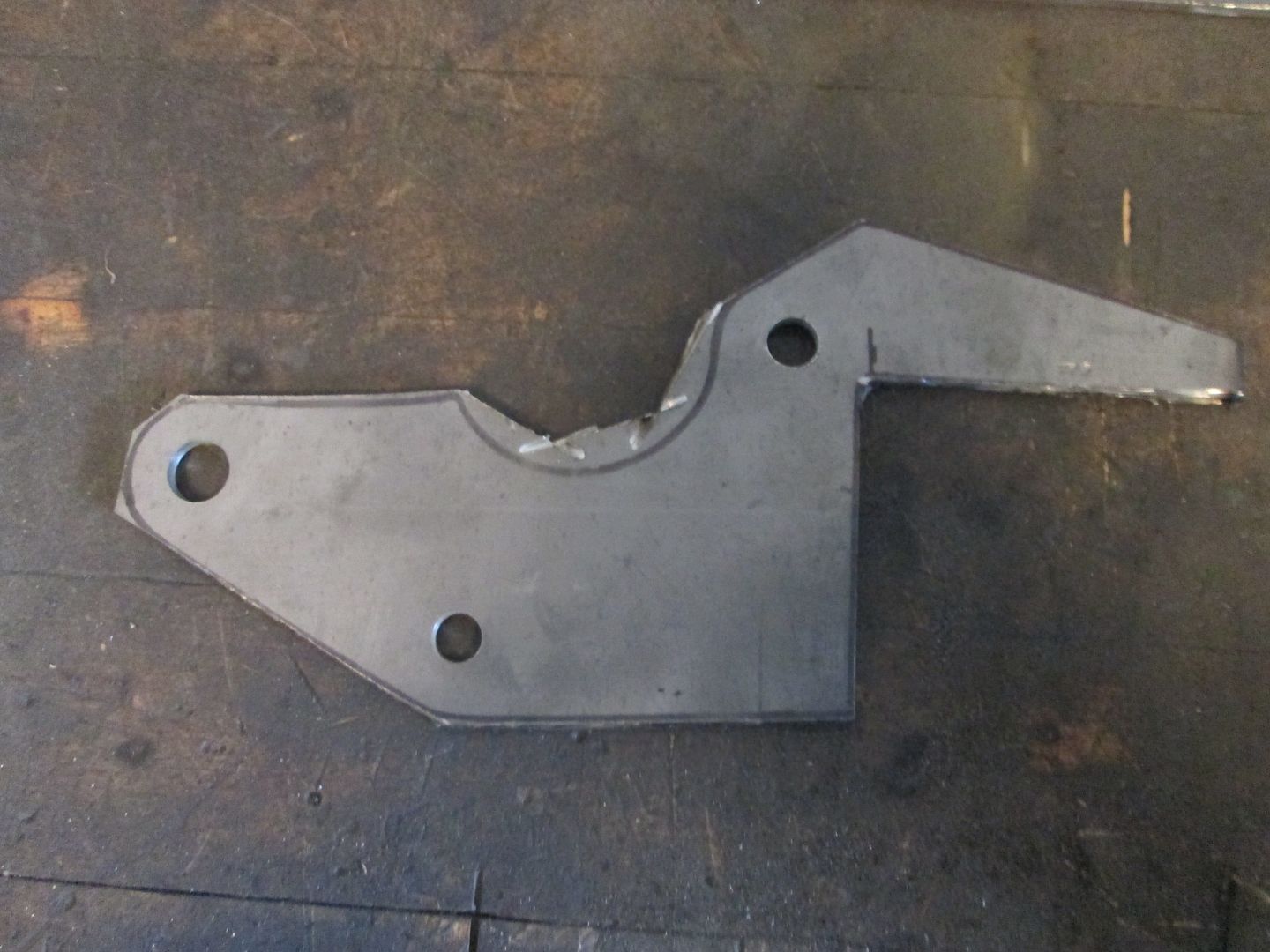
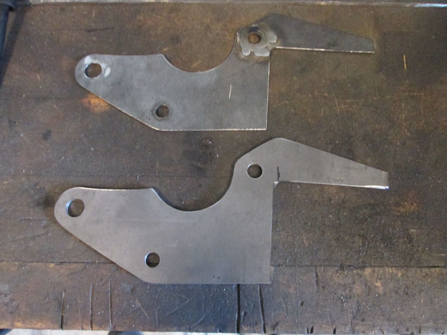
Here is the 16ga template I used for mockup and the spacers. This template will be transferred to 1/8" steel plate and cut to the same shape for the final mount:
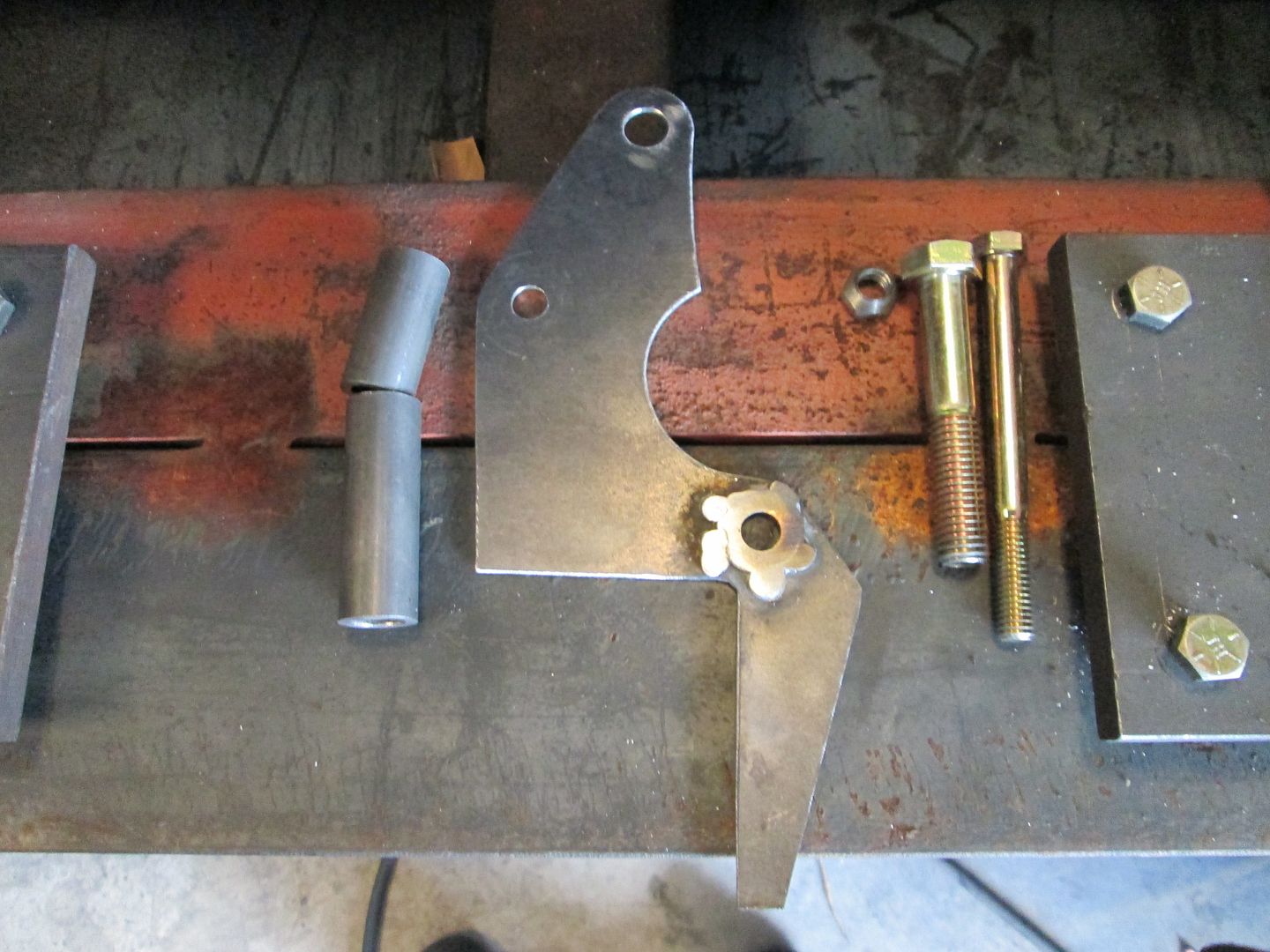
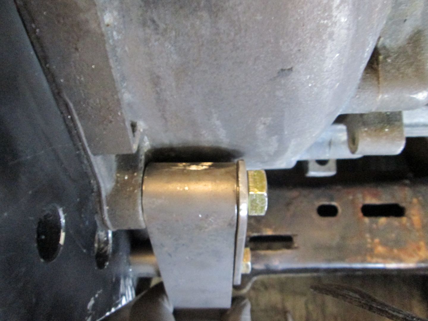
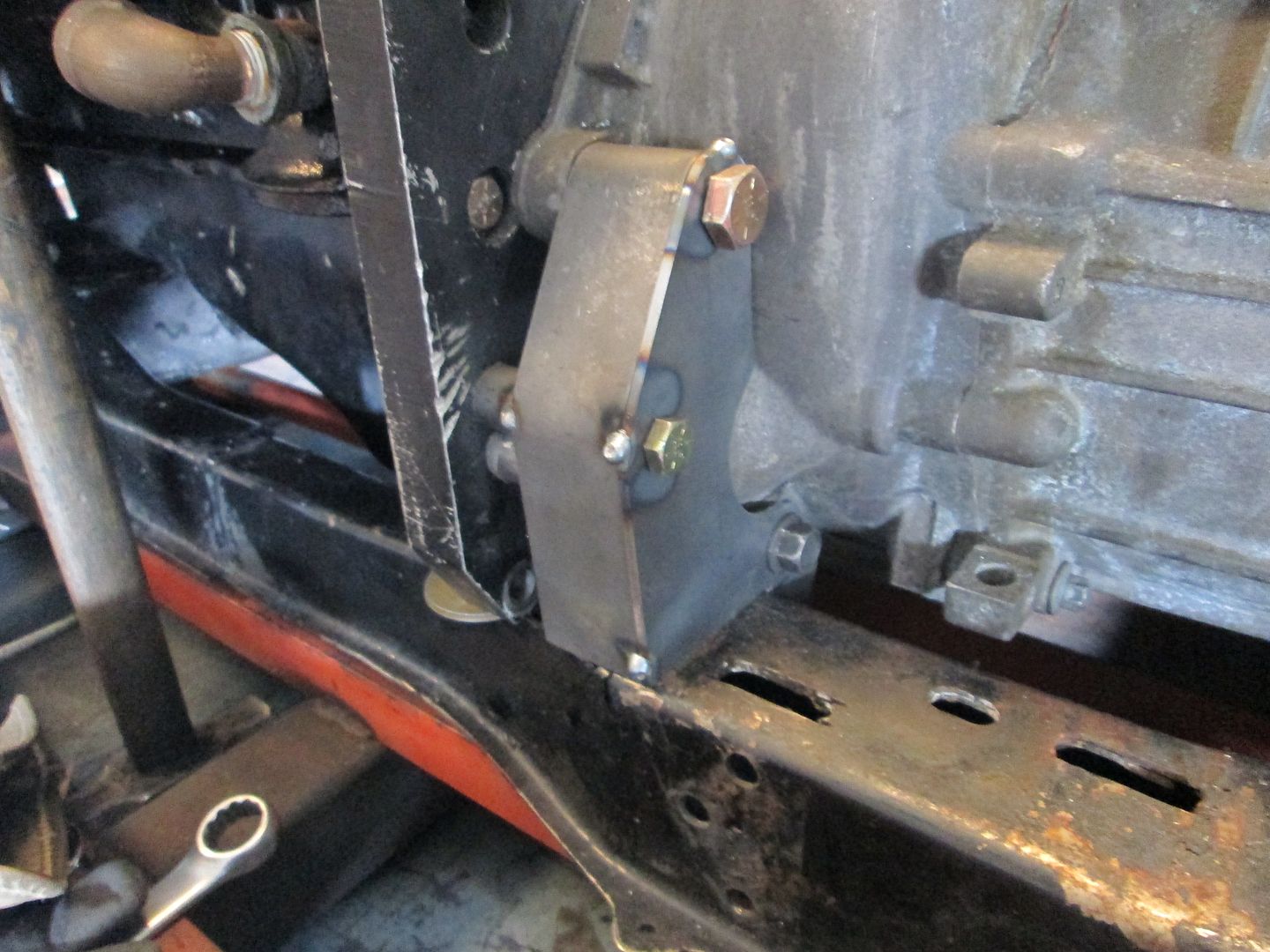
Notice the nice uniform gap between the bracket and the transmission case... I am anal like that:
There will be 1/8" plates that fill the gap between the spacers and down to the cradle. This will triangulate everything and result in a very strong/stiff mount made from 1/8" steel. The added steel plates will also completely hide the previous mods to the transmission case for the previous mounts:
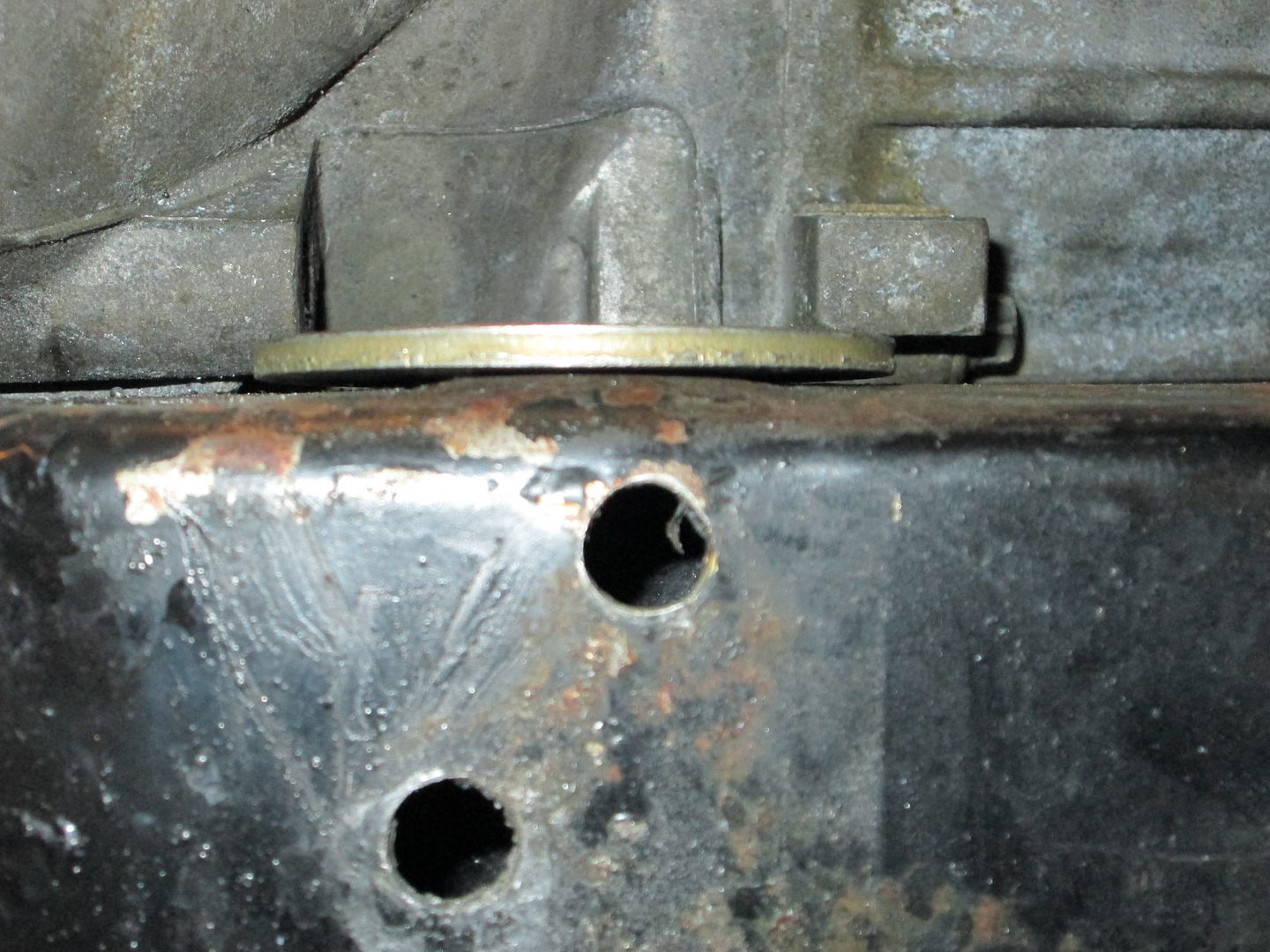
This mount will be welded directly to the front cradle rail to help spread out the load. The previous mount used 2 bolts and the cradle rail is bowed up where the drivetrain torque was too much for the metal around the 2 holes to properly hold. While this mount will be welded to the cradle, there will be a set of bolts for all mounts that secure the drivetrain in the same direction - remove the bolts and the drivetrain can be freely shifted to the passenger side for removal and lifting.
Sunday I hope to get this mount finished in 1/8" steel and start the mockup/template process for the rear one.
|
|
|
|
Trinten
|
AUG 17, 07:22 PM
|
|
I'm running out of laudatory words to use!
Though the discovery of my cradle showing stress from the torque makes me extremely glad about the timing of this project. Nightmares of what could have happened if that broke loose...
Thank you for the update!
|
|
|
|
Fierfly
|
AUG 17, 07:48 PM
|
|
|
I wish PFF had a 'like' button.
|
|
|
|
fieroguru
|
AUG 17, 07:56 PM
|
|
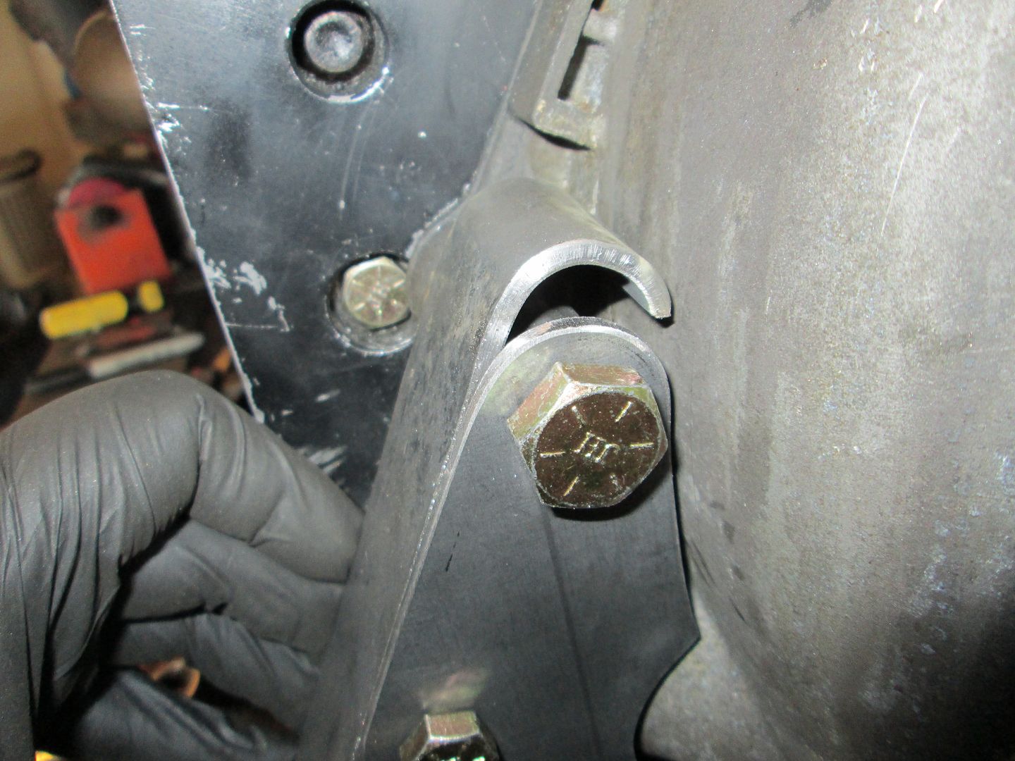
Here is a visual of the bent portion. The washer should be flat, but the center is bulged up where it was trying to pull through the enlarged bolt slot.
Your engine had 381 rwtq, so at the flywheel its pushing about 426 ft-lb (assuming a 12% driveline loss). With the F23 in first gear the axle torque (shared between the two axles) is 6008 ft-lbs... That is A LOT of torque for your mounts to withstand in the event you can hold traction in 1st gear.
For comparison, my LS4/F40 is 325 rwtq, so it is about 364 ft-lb at the flywheel and 4871 ft-lbs at the axles.
|
|
|
|
fieroguru
|
AUG 18, 01:01 PM
|
|
The front tranmission mount is nearly complete (just need to smooth the welds on the outside and finish welding it on the inside) and I thought it would be helpful to show a little bit more of the mount making process.
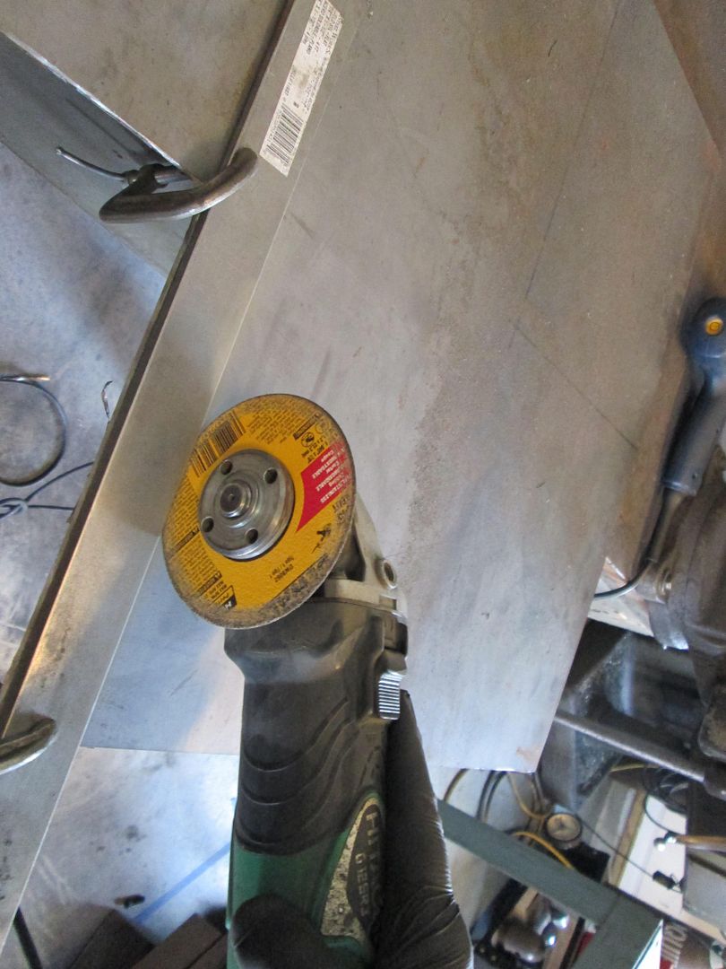
Starting with the template, I grab some 1/8" sheet and cut out a section of if for the piece I need:
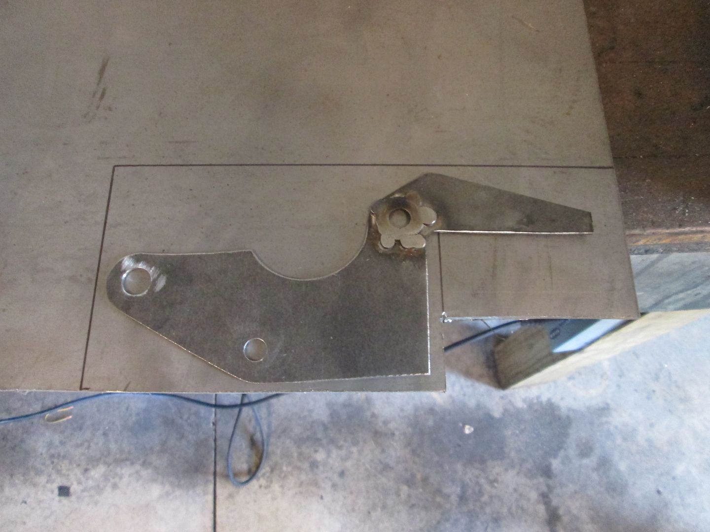
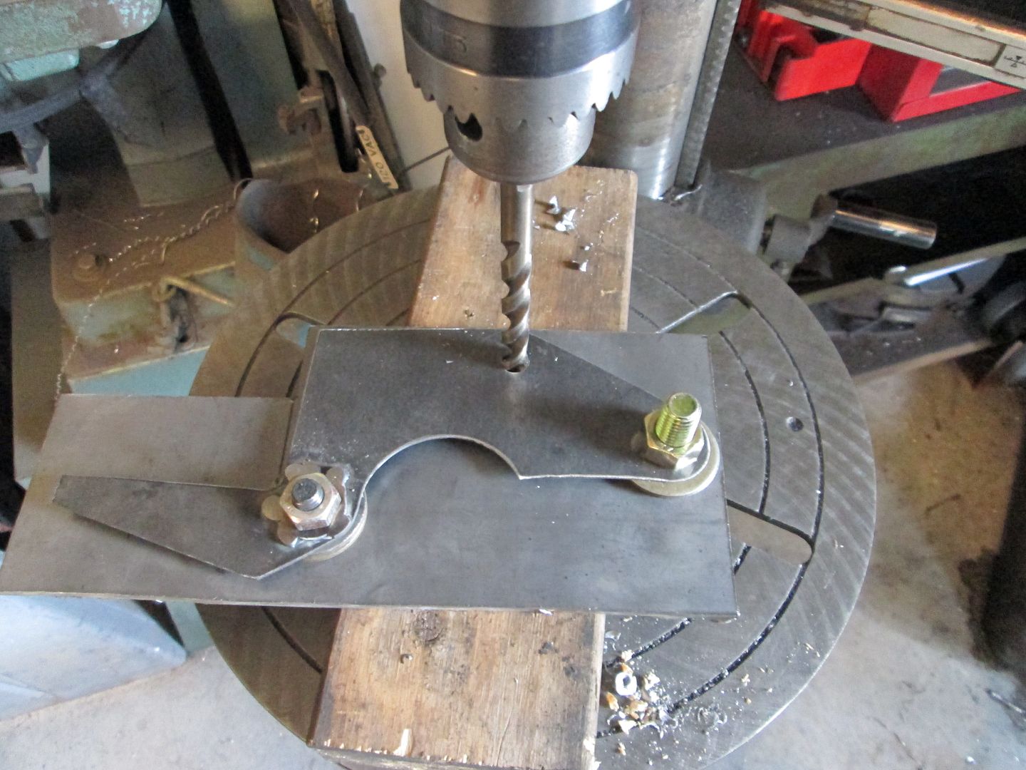
With the template sitting on the steel, I mark the first hole and drill it to the size of the bolt (keep the holes as tight as possible).
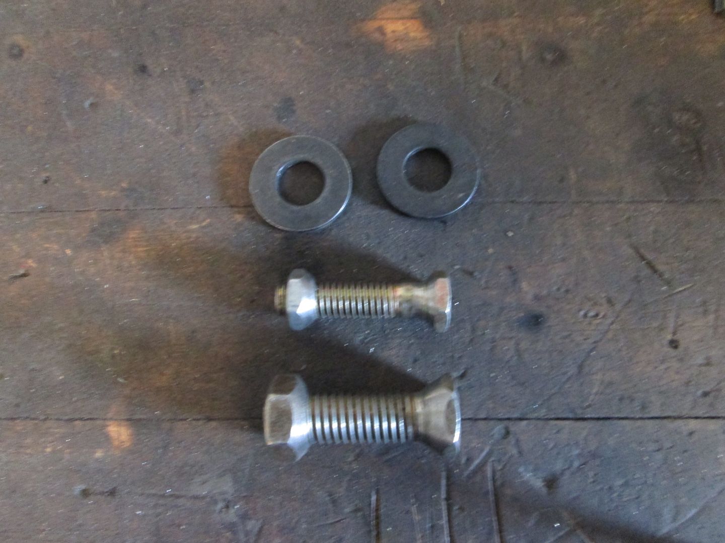
Once the hole it drilled, now tightly bolt the template to the steel plate and use 2 washers to keep the two separated. The separation allows the drill bit to center on the template as it drills the 1/8" plate. Drill another hole.

Then add a bolt to the new hole with the needed spacers and drill the next hole. By doing it way you keep the template secure and have a precise transfer of the bolt hole pattern from the template to the steel.
Now remove the spacers and bolt the two back together, then take a sharpie and mark the needed shape.
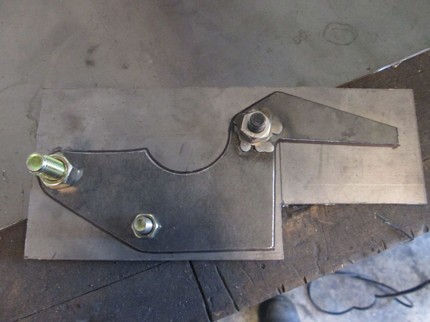
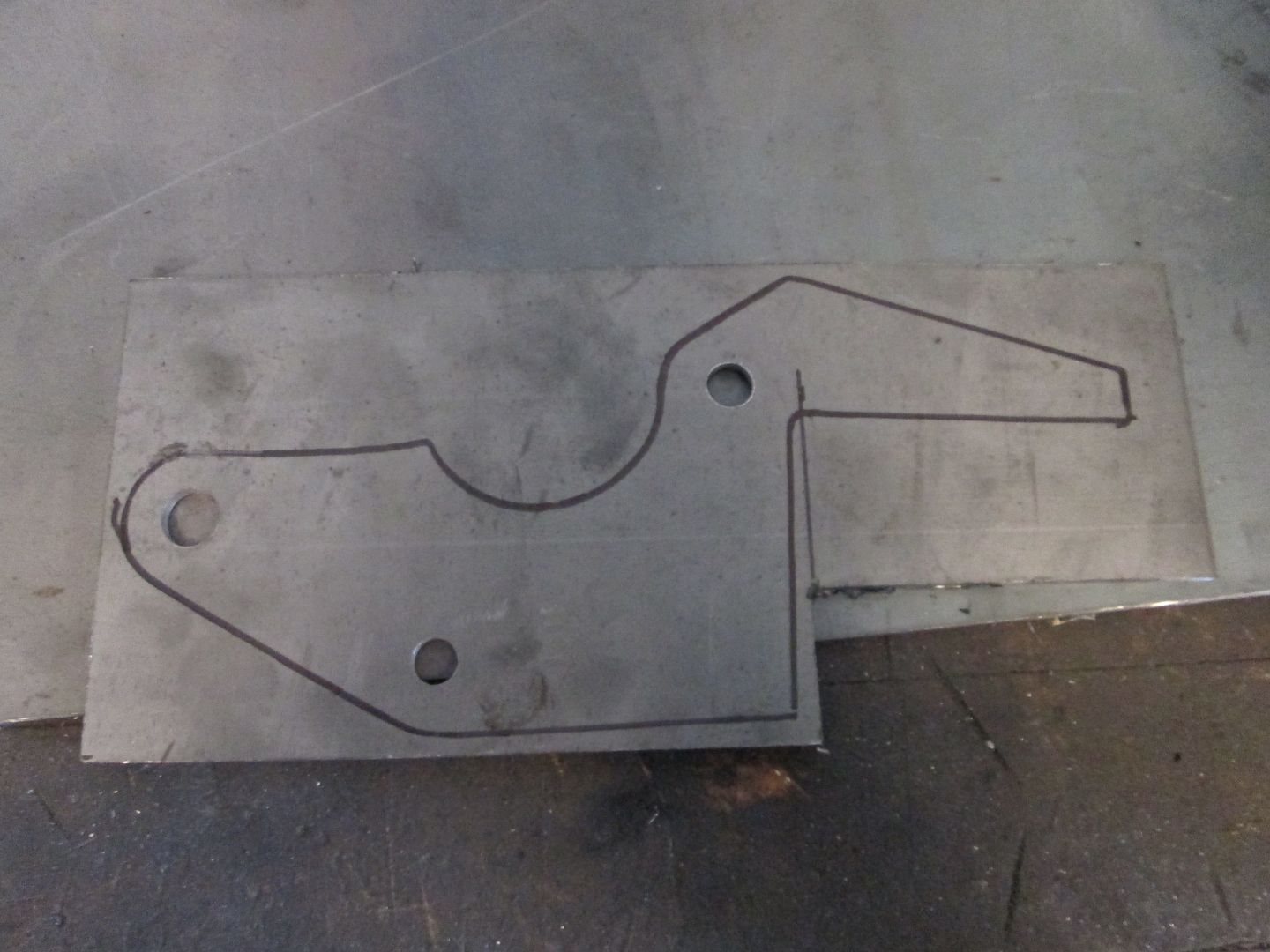
As you cut the shape out, cut in the middle of the sharpie mark and try to leave a little of the mark for finishing.
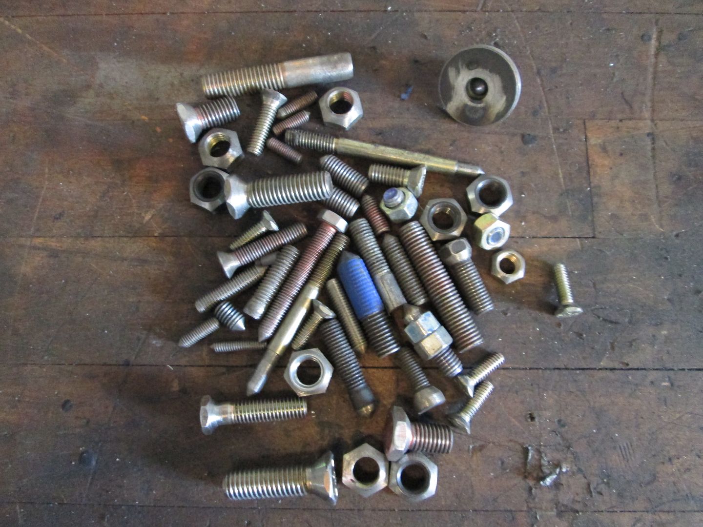
Once the rough cutout is done, bolt the two pieces together again, but now add washers to the holes that have smooth radii. If the washers with the right OD have too large of an ID to center on the hole, chuck up the bolt in the drill press and use the hand held grinder to taper the head or nut so they will self center to larger holes. Here are a bunch of modified bolts I have used over the years. The ones with the point are for transferring hole centers for making the templates, the tapered nuts and heads are for centering washers for shaping in larger holes.
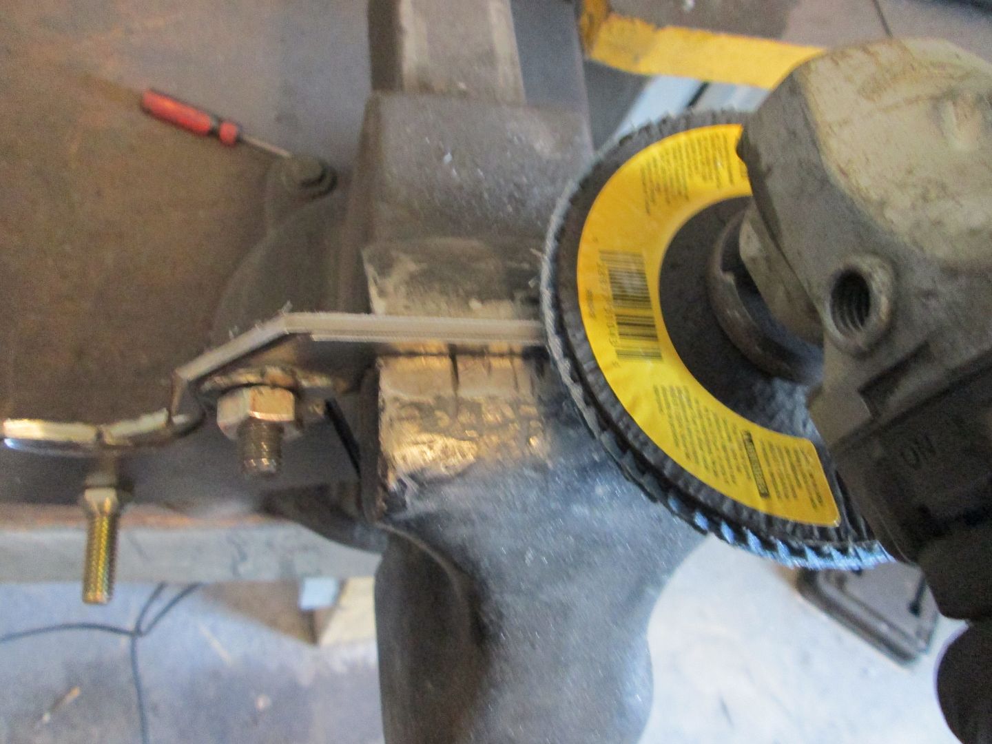
Then use a grinder with a flapper disk (36 grit) and slowly shape the plate to the shape of the template. Go slow you just want to scratch the template surface and the washers are you round the edges. With some work you will now have a copy of the template.
Next I use a belt sander to help flatten any straight surface (but a flat file works as well) and smooth out the edges.

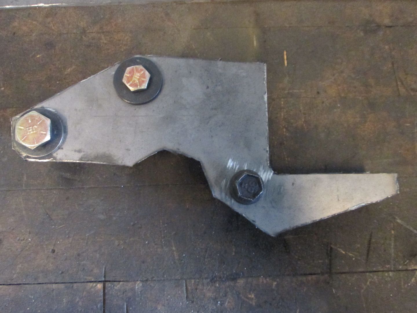
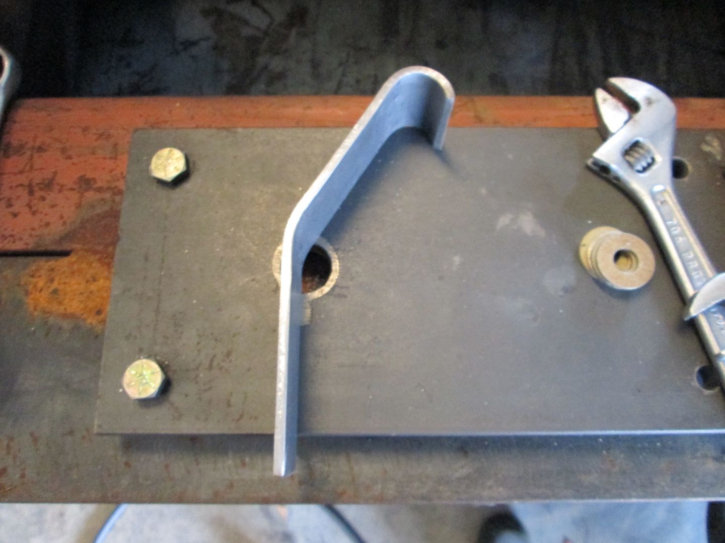
Here the 1/8" steel bracket is now done.
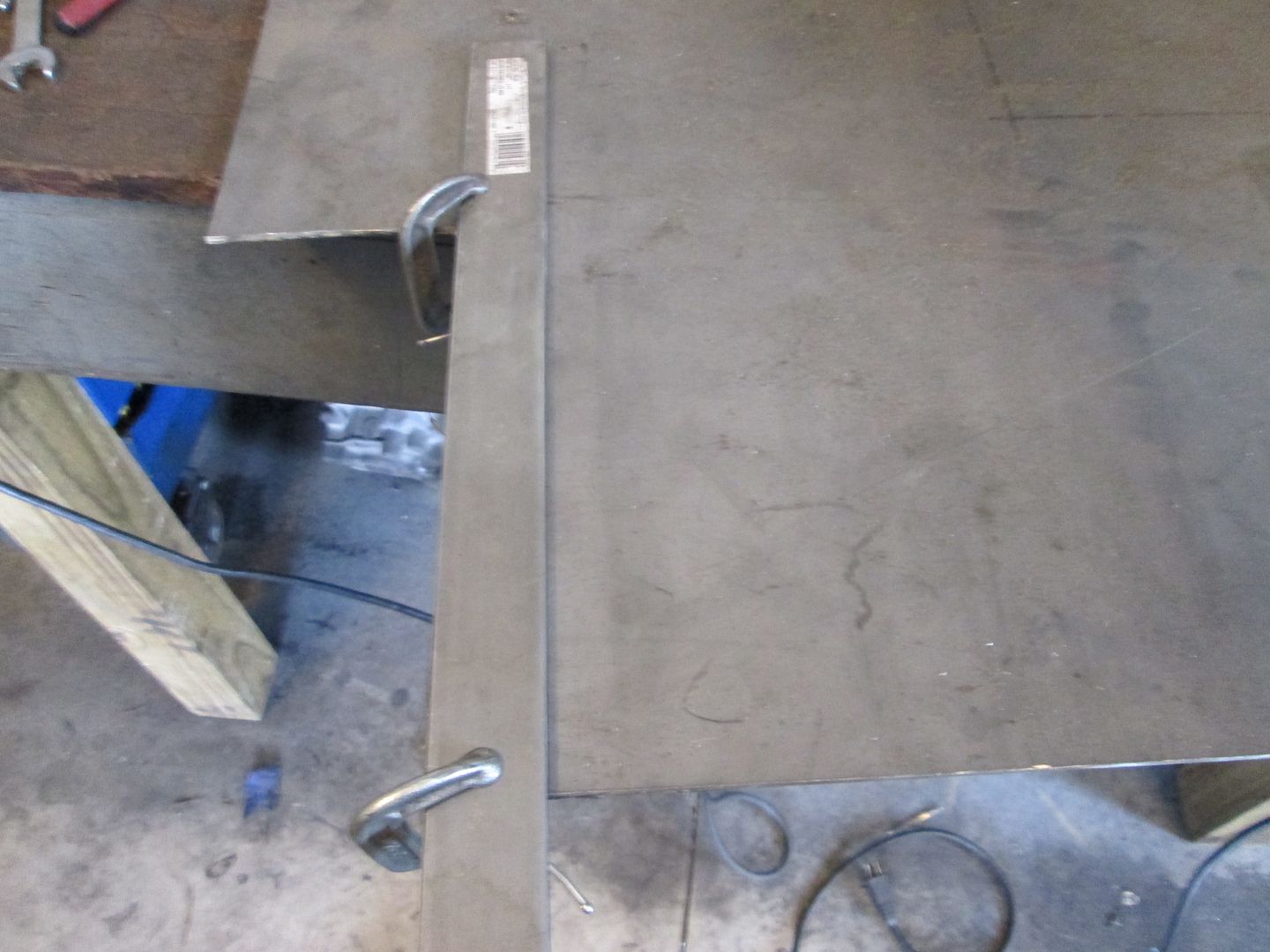
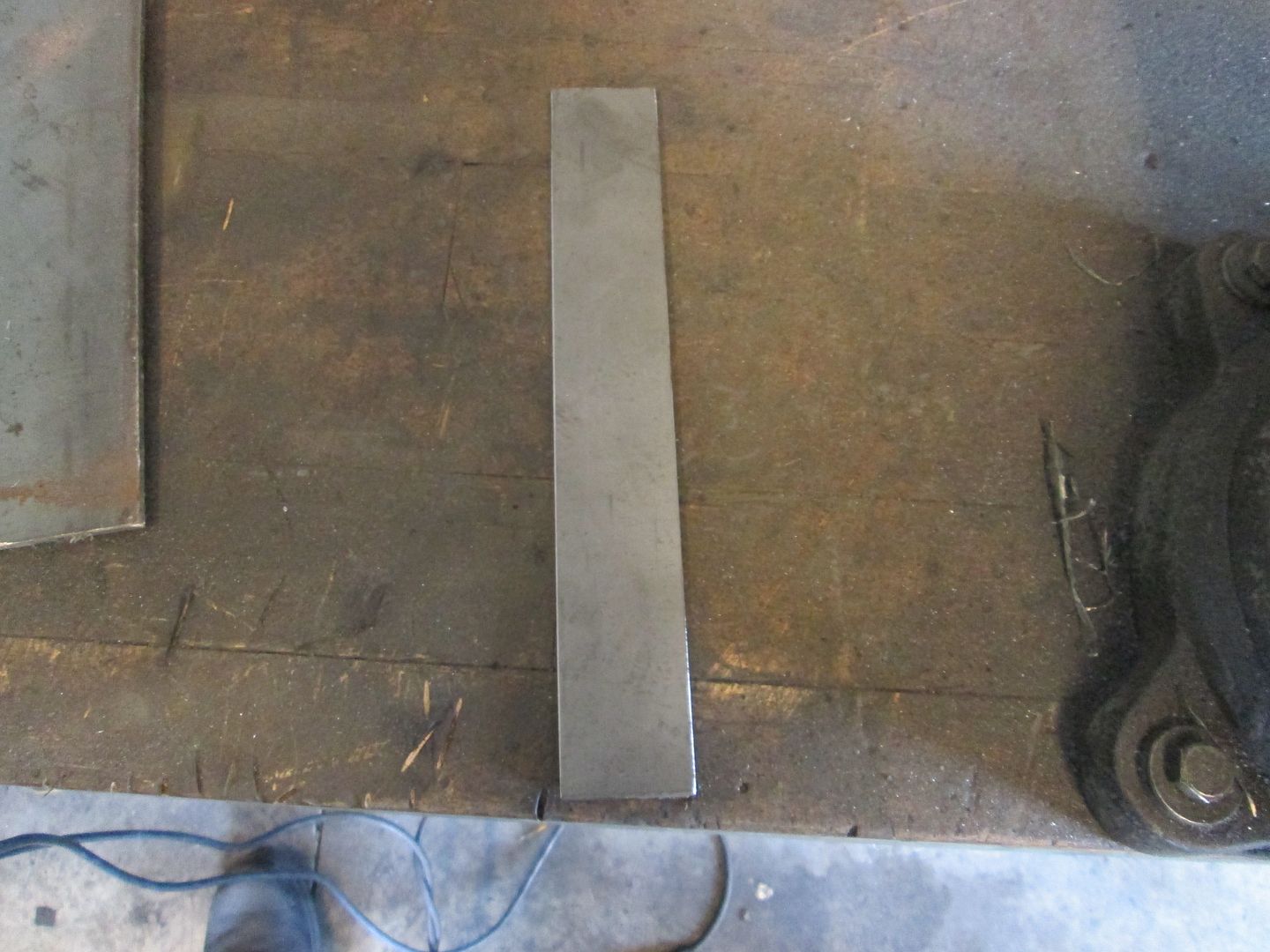
I wanted to add some 1/8" plate to the firewall side of the bracket to stiffen it up and hide the previous grinder work on the transmission, so I cut a long strip of 1/8" material 1 1/2" wide. When I want to make long cuts that are straight, I use another piece of steel as a guide and clamp it to the metal to be cut.
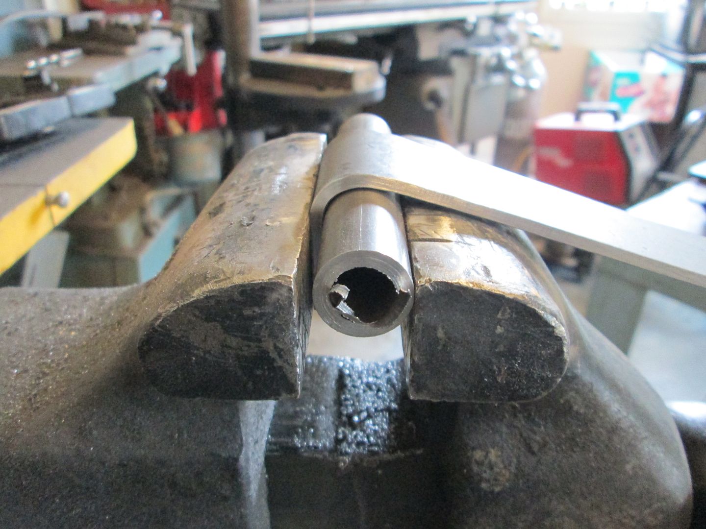
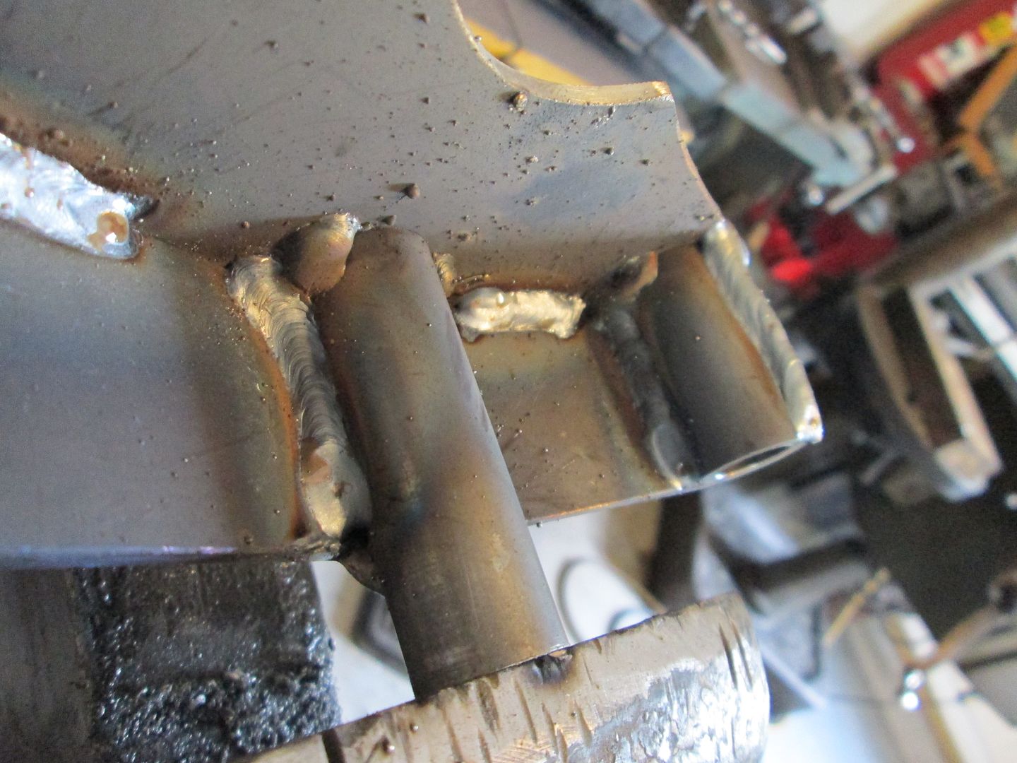
Now here is where I get a little fancy... I want this 1/8" plate to curve around the top spacer sleeve. To do this I grab another piece of stock used to make the spacer, clamp it on the vice and start pulling it over the tube. Several hits with the hand held mini sledge works to persuade it to bend tighter.

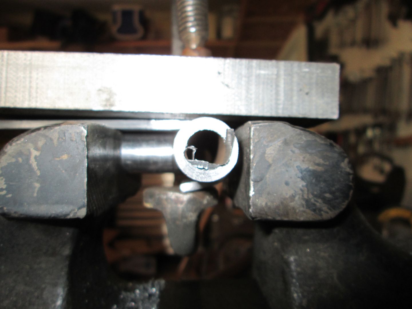
To go even tighter still, I clamp it in the vice using a socket to hold the tube tightly in the groove. Then use a large c-clamp to pull the short leg further around the tube. Once I am happy with it, I cut off the excess length of the leg and test fit the piece.
Then I slide the 1 1/2" plate into place and test the fit:
Then use the same process to make the 2nd bend around the other spacer and trim the bottom to the needed length:

Then I tacked the spacers to the original bracket plate on the inside, then tacked the outer plate as well. Then went back and fully welded the two together. I didn't focus on making a nice looking weld, just a hot deep weld with good penetration as it will all be ground down anyway.
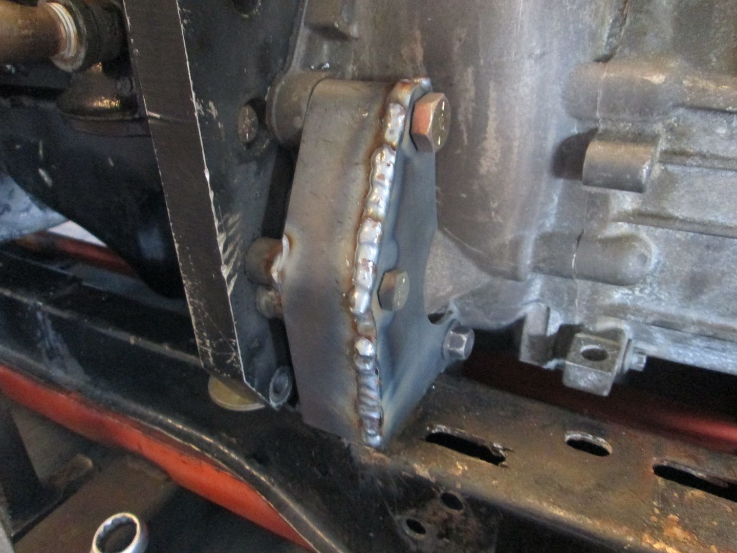
Backside is welded:
Last step is to grind the outer weld smooth, but the wife has a headache and would like for me to hold off on the grinding for a while. So I am going to mow the grass for a few hours.[This message has been edited by fieroguru (edited 08-18-2013).]
|
|
|
|
Raydar
|
AUG 18, 01:14 PM
|
|
|
|
|
FieroMaster88
|
AUG 18, 01:59 PM
|
|
|
|
|
Trinten
|
AUG 18, 02:07 PM
|
|

And you did all that today, and got the post put together, and it's still early in the afternoon. ... you can really make a guy feel lazy sometimes! 
With your bending setup, using the socket as a spacer on the pipe, is the pipe flattened out there? I would be worried about the pipe working/rolling free on the flat face of the socket when the wedging/bending force is being applied - or I could be missing something obvious that didn't translate in the picture/description.
|
|
|
|
fieroguru
|
AUG 18, 04:52 PM
|
|
| quote | Originally posted by Raydar:
Pure artistry. |
|
| quote | Originally posted by FieroMaster88:
 |
|
Thanks! My parents owned an ornamental iron business in the mid 70's and it must have made some impression on me at a very young age. I vaguely remember being there while they were working when I was young, and they shut it down when I was 3-4. Kinda strange that my adult hobby ended up being my parents first business... now that I think of it, my mom has only seen the bed I made for Sara and I, she has never seen any of the brackets/mounts I have made for my swaps...
| quote | Originally posted by Trinten:
And you did all that today, and got the post put together, and it's still early in the afternoon. ... you can really make a guy feel lazy sometimes!
|
|
So I guess I shouldn't tell you that I didn't even step foot in the garage till 10 AM...
| quote | Originally posted by Trinten:
With your bending setup, using the socket as a spacer on the pipe, is the pipe flattened out there? I would be worried about the pipe working/rolling free on the flat face of the socket when the wedging/bending force is being applied - or I could be missing something obvious that didn't translate in the picture/description. |
|
There is just enough pressure on the socket to hold everything in the vice, and the tube is 1/8" wall and quite stiff. The clamping/bending is happening with the large C-clamp, not with the vice at this point.[This message has been edited by fieroguru (edited 08-18-2013).]
|
|
|
|