
 
     |
| Blooze Own: An F355 Six Speed N* Build Thread (Page 14/126) |

|
Bloozberry
|
JUN 08, 10:02 PM
|
|
Mercy me... a Murci? Have you posted images of it here yet on PFF? What's it got for an engine? As for total engine costs I keep a detailed record of all my expenses to help the insurance appraiser come up with a replacement value for the car, should the need ever arise. The engine, engine parts, and machining to date (not including flywheel, and PCM tune) have cost me about $5150. Really not bad at all.
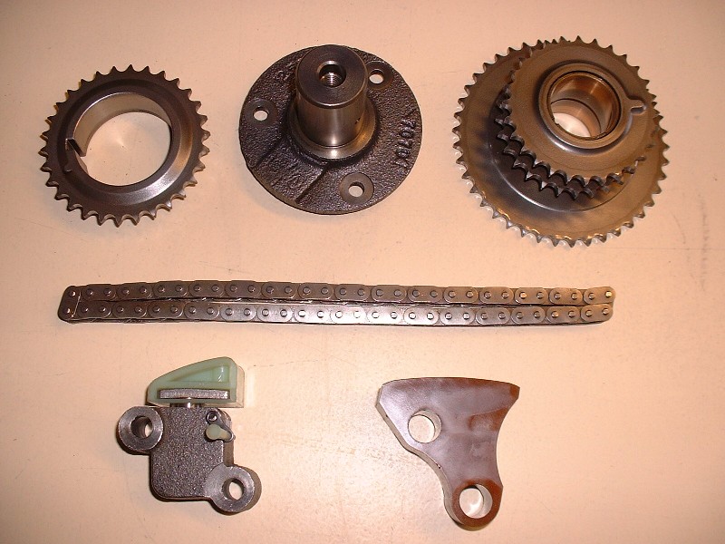
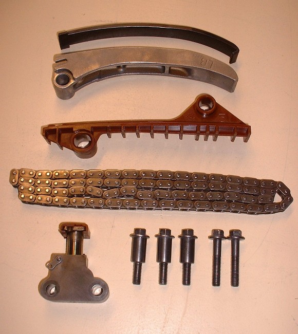
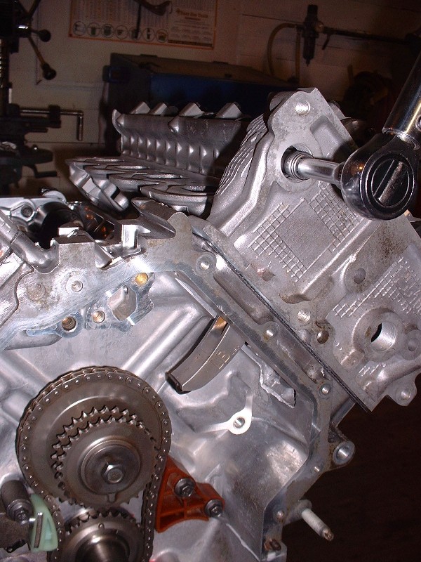
OK, so with the starter out of the way, I moved on to the valve timing components. It was a lot more intimidating and time consuming to read through the process than it was actually doing it. Once all the parts were cleaned up and inspected, I opted to keep all of the original timing components except the primary chain tensioner. If you've been following from the beginning, you'll remember why. So here now are the components that form the primary timing chain assembly from top left to bottom right: crank sprocket, intermediate sprocket set journal assembly, intermediate sprocket set, chain, tensioner, and guide.
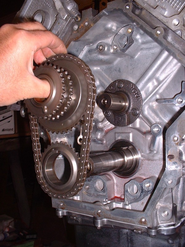
The first step is bolting on the intermediate sprocket journal assembly. It’s a no-brainer. Interestingly though, it gets fed pressurized oil from a hole in the back-side, and directs the oil to the sprocket set via rifle-drilled holes in the journal surface. Three bolts hold it in place.

Next up is to install the crank sprocket, intermediate sprocket set and the chain all in one shot. Before you do that though, you have to align a pair of dots on the two sprocket sets so that the dot on the crank sprocket is pointing straight up and the dot on the intermediate sprockets is straight down. Again, it’s not rocket science or brain surgery. Both sprocket sets just slip right onto their respective shafts without any fuss. (The intermediate sprocket set is actually machined from a solid piece so you don't have to worry about aligning them to each other).
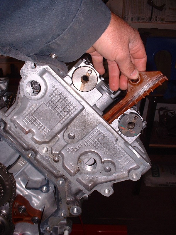
There’s a fair bit of slack in the chain at this point, so you want to make sure that the chain is tight on the side that gets the guide, and loose on the side that gets the tensioner. Here’s me installing the guide and torquing it to 18 lbft.
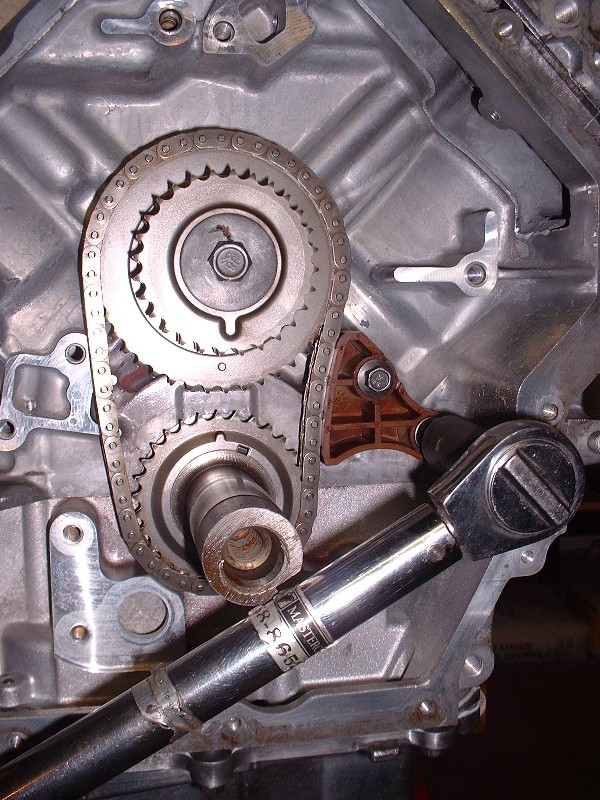
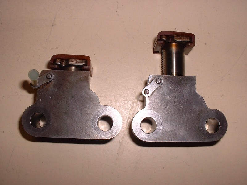
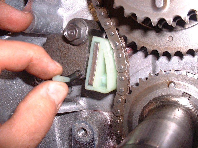
The last component to be installed is the tensioner. When you remove the tensioner on the teardown phase, it springs to its fully extended position. To reinstall it, you have to rotate a little spring loaded lever on the side of the tensioner, push the piston back into the block, and stick a peg in the hole in the little lever. The peg keeps the piston from shooting back out. Here’s a picture showing how much travel there is in these little suckers. (These are actually secondary timing chain tensioners, but the primary tensioner is similar, as you'll see in the next photos.)
So here’s the brand new primary tensioner being installed. Again, just two bolts tightened to 18 lbft.
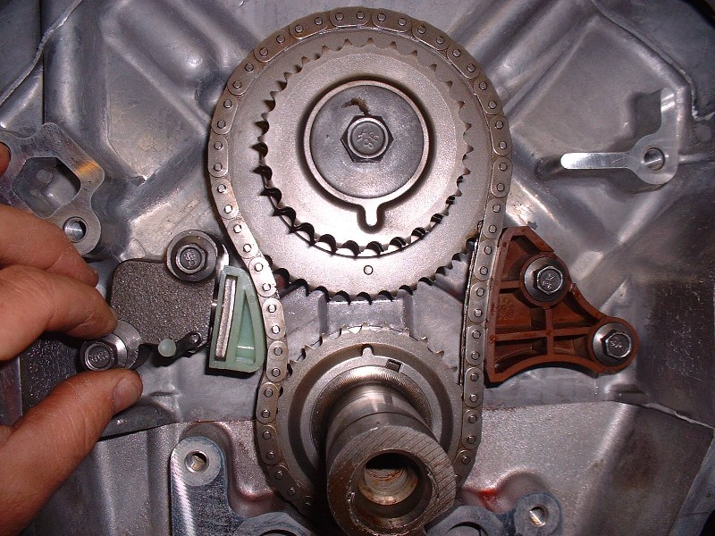
And finally, once you make certain that the little dots on the two sprockets are perfectly aligned, you pull the peg and let the tensioner take up the slack in the chain. Too easy. The cam chains on the other hand are a little more work. That's next.
|
|
|
|
Bloozberry
|
JUN 10, 10:18 PM
|
|
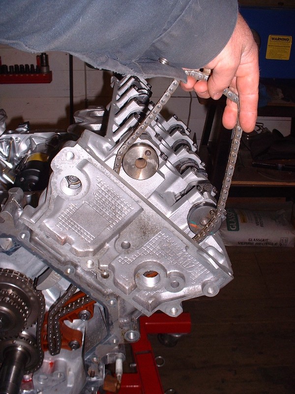
Here are the main components of the secondary timing chain system from top to bottom: replaceable upper chain guide shoe; upper chain guide; lower chain guide; chain; and tensioner.
The first step is to install the shoe on the metal upper chain guide and slip the guide through the top opening of the chain case (this is the guide that will have the tensioner pushing its backside).
On the front (or left, or even) cylinder bank, this guide is mounted above the chain and is secured in place with one pivot bolt that’s reachable through one of the holes that’s been bored and tapped in the front of the chain case like this:
The lower chain guide on this bank is made of plastic and it goes in through the top like the upper one, except it has two bolts that secure it in place.
Once that’s done, you slip the chain through the top of the case as well, feeding between the two guides, and hang it over the ends of the cams like so:
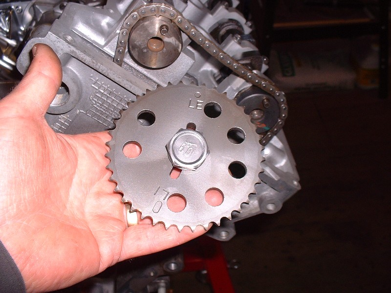
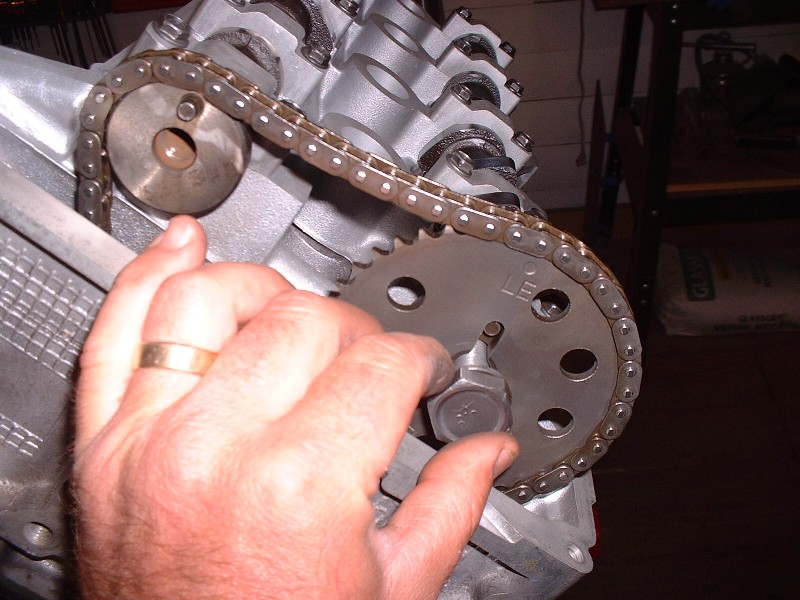
Even though the Northstar wasn’t used in any longitudinal applications at the time this ’97 was built, GM still called the different banks LEFT and RIGHT. So for the Fiero application, the left bank is the front bank, which are also the even numbered cylinders. You need to know this when you go to stick on the cam sprockets, which are next. The intake and exhaust sprockets on the left (front) bank are identical but they go on in different orientations. Here you can see that the locating pin on the camshaft slips into either of two slots depending on which cam it’s destined for (ie left intake cam (LI) or left exhaust cam (LE).
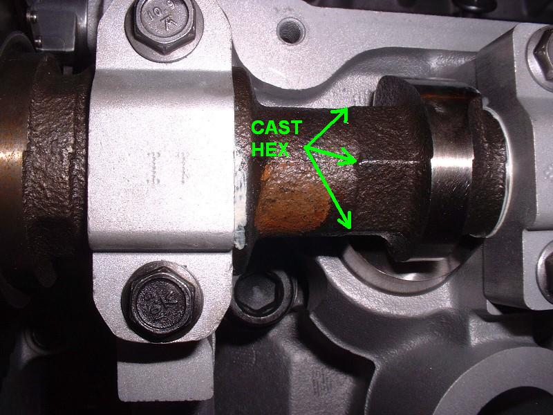
Before you can slip them on though, you’ve got to rotate the camshafts so the pin on the end of them is at 90* to the valve cover mounting surface. Because the cams are under a fair bit of tension from the valve springs, GM had the fore-thought to cast a hex onto the cams so you can turn them with a wrench… that was handy.
Next you slip the chain around the inner of the two primary sprockets down below, then slip the chain onto the exhaust cam sprocket in such a way that when the sprocket is installed on the exhaust cam, that there's no slack on the chain segment lying across the plastic lower guide. The chain should fit just right so if there’s any slack, double check that the dots on the primary sprocket set are perfectly aligned, and that the exhaust camshaft pin is at exactly 90* and turn either one as necessary.
Once that’s done, then slip the intake cam sprocket onto the chain so that when it’s installed on the intake cam, that there’s no slack on the chain segment between the intake and exhaust sprockets. To do this, you may need to reposition one or both cams a little using the wrench because if either cam pin isn’t perfectly at 90* you’ll find it impossible to install the chain without it sagging between the sprockets.

At this point, all the slack in the chain should be on the chain segment between the intake sprocket and the primary sprocket down below. That’s because the chain tensioner is what will eventually tighten up that segment… but not yet.

The next step is to install the rear/right/odd bank chain set. It’s similar but not exactly the same as the front/left/even bank[This message has been edited by Bloozberry (edited 07-13-2010).]
|
|
|
|
Tony Kania
|
JUN 11, 12:51 AM
|
|
As I said earlier, just amazing! 
| quote | Originally posted by Bloozberry:
Mercy me... a Murci? Have you posted images of it here yet on PFF? What's it got for an engine? As for total engine costs I keep a detailed record of all my expenses to help the insurance appraiser come up with a replacement value for the car, should the need ever arise. The engine, engine parts, and machining to date (not including flywheel, and PCM tune) have cost me about $5150. Really not bad at all.
] |
|
I have witnessed said Murci.  I will let the owner explain her, but what a car! She definately has curb appeal. The lines are really proportionate, and not at all boxey or out of place. I have pics, but will post only if Dratts says it is cool. I will let the owner explain her, but what a car! She definately has curb appeal. The lines are really proportionate, and not at all boxey or out of place. I have pics, but will post only if Dratts says it is cool.  Oh, please let me post them? Oh, please let me post them? 
And Dratts, I will be at FieroKing's tomorrow. Maybe it won't snow this time? 
EDIT: As to not take up Blooze's space, I will post a thread in the General section. I have some very appealing pics of your car. [This message has been edited by Tony Kania (edited 06-11-2010).]
|
|
|
|
dratts
|
JUN 11, 11:23 AM
|
|
|
Hey Tony, Sure, post away. It's got a 350 tbi vortec in it for now. It's at midtown motors ruight now getting a new interior. I'd post more but I don't want to distract from bloozes fantastic story. I'm learning more than I'll ever need to know about N*s but it's always nice to know what's under your hood.
|
|
|
|
cptsnoopy
|
JUN 11, 06:32 PM
|
|
Blooz makes it look so easy I am surprised we don't have a rash of N* rebuild/installs being posted...
Charlie
|
|
|
|
Bloozberry
|
JUN 12, 09:37 PM
|
|
Tony, thanks for posting those pics of Dratts car... that is one awesome looking ride. Dratts, that thing looks all Italian, but with that 350 TBI in it I'll bet it sounds all Detroit! Nothing one of your Northstar engines couldn't solve though. Charlie and I will walk you through it.
Anyways, I must admit when I went to install the rear bank timing chain parts, I started to doubt myself. In my head, I imagined the installation would be the mirror image of the front bank’s set-up, but came across my first hurdle when I went to install the upper guide. It wouldn’t fit no matter how I turned, squeezed, or willed it into place.
But then it struck me… if the chain guides were installed as the mirror image of the front bank (ie with both tensioned guides at the top) then the front bank would work properly but the rear would have the crank’s power being applied to the slackened segment of the chain. That wouldn't work well... remember the chain is only pulled, not pushed by the crank. So for the whole thing to work properly, the rear bank’s hardware would have to be installed as though it were removed from the front bank, lock, stock and barrel, and simply rotated around the crank's axis like the hands of a clock. (I have no idea whether that makes sense to anyone except me, but at least all the pieces fit!)
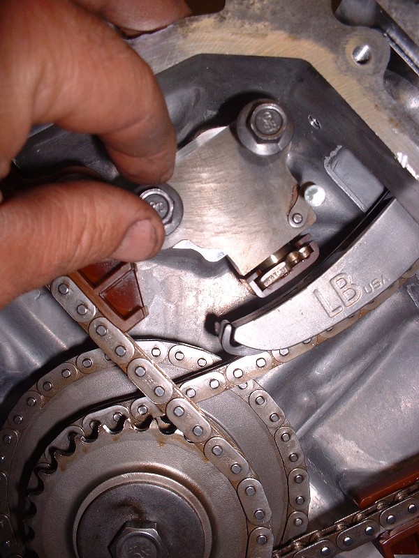
So once the upper and lower guides were in, the next step was installing the cam sprockets, as before. Except that one of the rear (right) bank sprockets has a pin on it that none of the others do. It pays to notice the little things because no mention of this is made in the Service Manual. The pin is part of the camshaft position sensor circuit. The sensor gets installed on the side of the head where the exhaust cam is (at least that's where the hole is!), so it became pretty obvious which sprocket had to go where.

The rest of the installation is similar to the front bank. Once the chain is sorted out and the slack is on the proper side of each sprocket, the tensioners for both sides are installed and the little release pins are pulled. Notice the big “LB” for Left Bank (or lost bonehead).
To keep the road grime out, the access holes for the chain guide bolts are then plugged with threaded plastic bungs. They have an o-ring on the backside that seals up tight against the cylinder head.
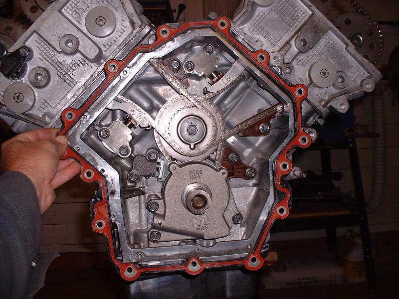
So when it’s all said and done, this is what it’s supposed to look like. Each chain has a stationary guide (on the powered leg of the chain) and a pivoting guide with a tensioner holding it tight against the return-leg of the chain. It looks busy, but it's really quite simple. Personally, I had expected it to be somewhat confusing to set up the timing chains after reading about the process and having seen other people’s threads, but it turned out to be straight-forward.

|
|
|
|
stickpony
|
JUN 12, 11:23 PM
|
|
| quote | Originally posted by 17Car:
Looking good, nice to see some progress on the project.
You have more guts (and money) than I do to rebuild a Northstar. Seeing how complex it is makes me wonder if I should have went with a 3800, I'll feel different when my swap is done.
Did you consider a set of CHRFabs cams? I believe that they are only about $500 for a set. Beats $700 a piece and it's an upgrade, but I will be interested in how your refurbished cams hold up.
Edit: Hooray! I own my first page ever!
|
|
agreed... its much cheaper to get a crate engine off ebay these days than rebuild an N*... i understand his angle though, as building it yourself is peace of mind, since you KNOW it will be done right, as long as one knows what one is doing
|
|
|
|
Bloozberry
|
JUN 17, 09:07 PM
|
|
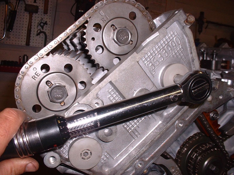
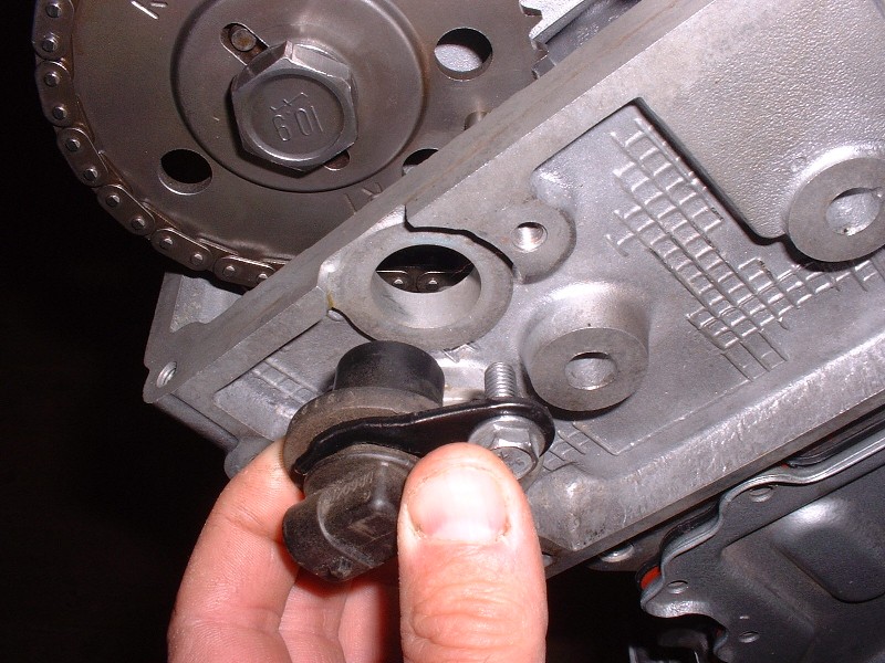
I’m back after a short break working on a ’67 GTO convertible… almost done. So after the chains were in place, I installed the camshaft position sensor in the hole next to the rear head exhaust cam sprocket. It senses the passing of the little metal pin on that sprocket for timing purposes. Like all of the the M6 bolts, the sensor hold down bolt goes on with 89 in-lb of torque. The difference with this little guy however is that it goes right through to the innards of the chain case so it needs a little dab of RTV on the threads to keep it from leaking.
The last thing before the chain case can be buttoned up is the oil pump. I ordered a new one on spec as cheap insurance even though the old one looked OK. They're a pretty robust pump. I was surprised that the new pump came with a drive sleeve, because I can’t see why this part would need to be replaced. I used the new one anyways… it just slips onto the crankshaft.
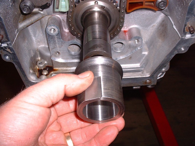
To get the new pump on, you simply line up the flats on the drive sleeve with the mating flats on the pump rotor. It too just slips on. Surprisingly, there are no O-rings or other seals between the inlet and outlet ports of the pump, and the mating surfaces of the block.

To hold the pump in place there are three screws that must be tightened in a particular sequence and then turned an extra 35*, and you’re done.

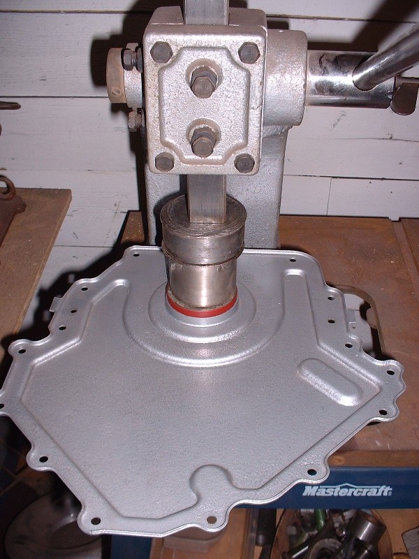
Before the chain case cover can go on, there’s a couple things you have to do. The first is to replace the front crank seal in the cover. Getting the old one out was a cinch… I just used my arbor press and pressed it from the front side, out through the back side. If you haven’t got a press, then a few carefully placed hammer blows with a punch would do the trick.
Getting the new one in wasn’t as easy. No matter what I did, the seal always seemed to get started cockeyed. I worked at it for fifteen minutes trying to get it to start all the way around to no avail. It’s as if the seal was a smidgen too large for the hole. So I decided to use my Dremel with a small sanding drum and chamfered the edges of the hole in the cover. Once that was done, the seal pressed straight in.
The second thing to do before the cover goes on is to use a straight razor and slice off any engine sealant that oozed out or is protruding from the case-half split line at the front of the engine. Then you’ve got to place another dab of fresh sealant in the same two spots.
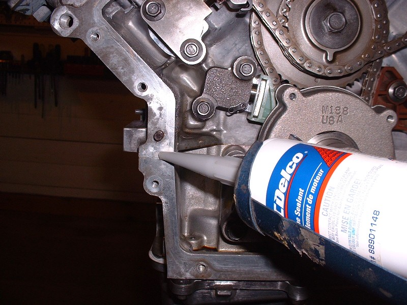
The third thing is to put a new cover gasket in place. It’s got two holes that line up with corresponding alignment pins so there’s no need to try to hold everything in place. The new seal came with the master engine rebuild kit. It’s made of a hard composite material that’s got an orange neoprene-like seal impregnated in it on both sides.
Finally the cover gets put in place… forever sealing up the beautiful mechanical artwork underneath. My cover was a little pitted so rather than filling the pits with body filler, I sandblasted it, primed it, and sprayed it with a Tremclad silver paint that gives a “hammered” look to it once dry. I didn’t want to waste too much time on a part that will not be seen.
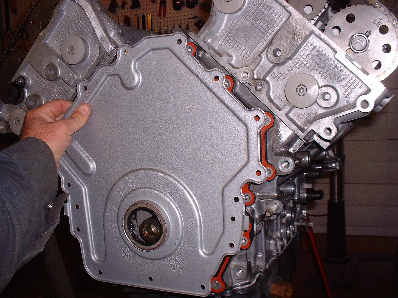
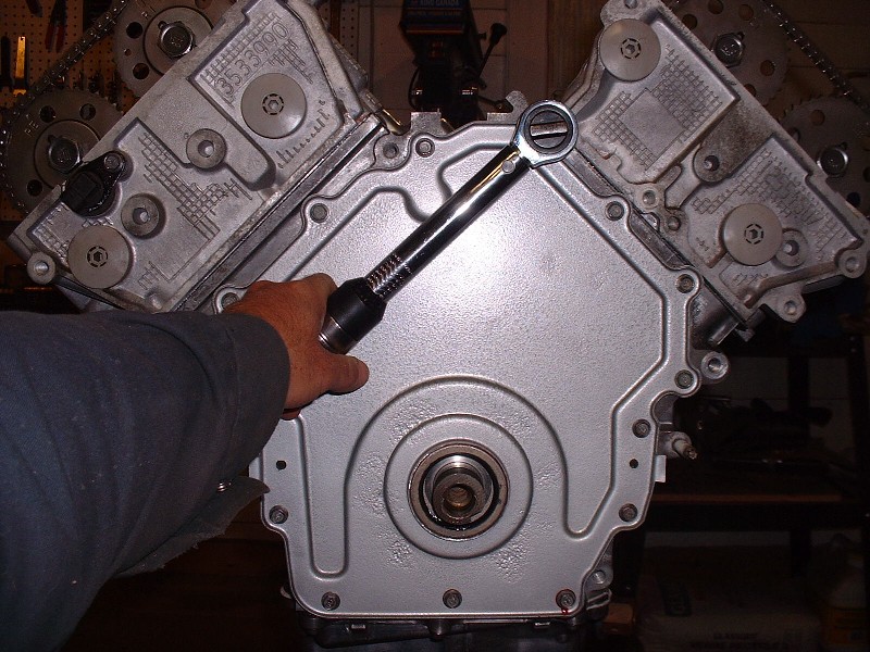
The cover gets torqued on (you guessed it) to 89 in-lbs starting at the bolt I’m torquing in this picture, and going around successively to the next bolt in a clockwise direction until you’ve done all fifteen. Then, if you’re smart, you go over them one more time. The service manual states that a thread locking compound must be used on these so I used the high temp red Locktite left over from my head bolt inserts.
|
|
|
|
aaronkoch
|
JUN 18, 12:17 AM
|
|
|
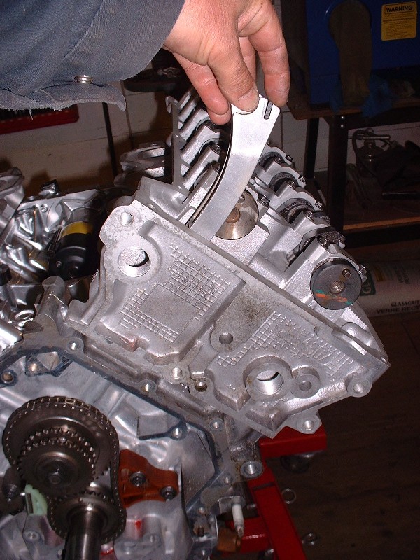
Man, in that last pic you really get an idea for how MASSIVE those engines are.. Just insanely big. (physical dimensions wise)
|
|
|
|
Nashco
|
JUN 18, 08:32 AM
|
|
| quote | Originally posted by Bloozberry:
I didn’t want to waste too much time on a part that will not be seen. |
|
Given the amount of time you put into that starter, that's kind of funny that you'd say this about the timing cover. Maybe the starter taught you a lesson? 
Thanks for the documentation, I enjoy reading/seeing it!
Bryce
|
|
|
|