|
| LS4 / F40 swap - fieroguru (Page 137/216) |

|
fieroguru
|
MAY 28, 02:23 PM
|
|
|

|
motoracer838
|
MAY 28, 03:04 PM
|
|
| quote | Originally posted by fieroguru:
The only thing I would add is to swap to a LS2 or LS3 timing cover. The LS4 cam sensor is in an odd ball location, so if you ditch the LS4 ecm, then swap the timing cover as well.
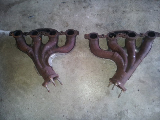
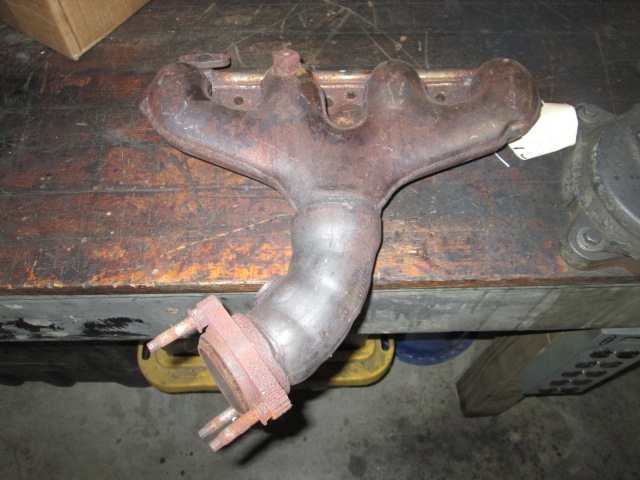
You might want to consider some of the earlier exhaust manifolds as a lower cost option to the LS7. These are OEM stainless as well. I would cut them off before the bend, but that is just me.
Most of my more recent developments for the LS4/F40 are in this thread...
http://www.fiero.nl/forum/Forum1/HTML/094411.html
|
|
Thanks for the tip on the timing cover, about the cam, I'll take a look at something better once I see how much money I've spent getting there.
LS1 manifolds are an option, I have a set on my 98 C5 parts car, the trouble is it still moves under it's own power, disabling before I'm ready to take it apart will make it a major pain to move.
It's been a while since I looked in on that thread, I remember that joker fishing for info on the water pump... 
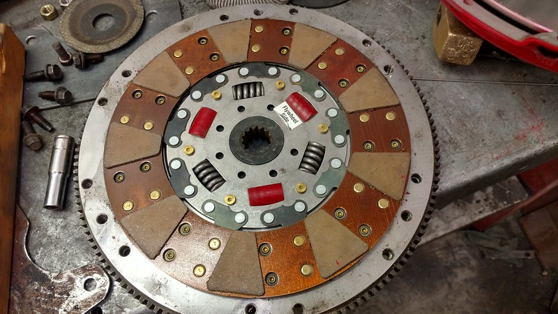
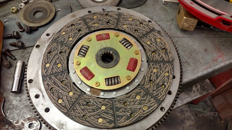
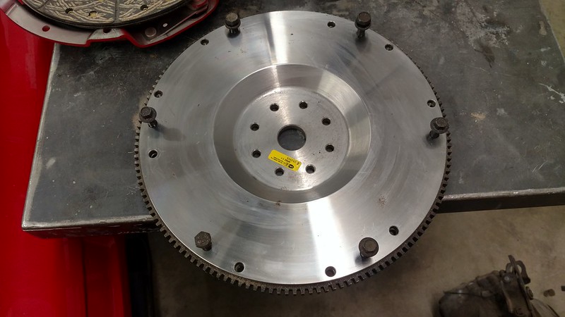
At this point I think the flywheel I have can be made to work, need to call McCleod to find out if the clutch they supplied to CHRF is up to the task, if memory serves the disc is 9 11/16", need to take a look.
Joe[This message has been edited by motoracer838 (edited 05-28-2018).]
|
|

|
motoracer838
|
MAY 28, 05:01 PM
|
|
|
|
|
fieroguru
|
MAY 28, 07:49 PM
|
|
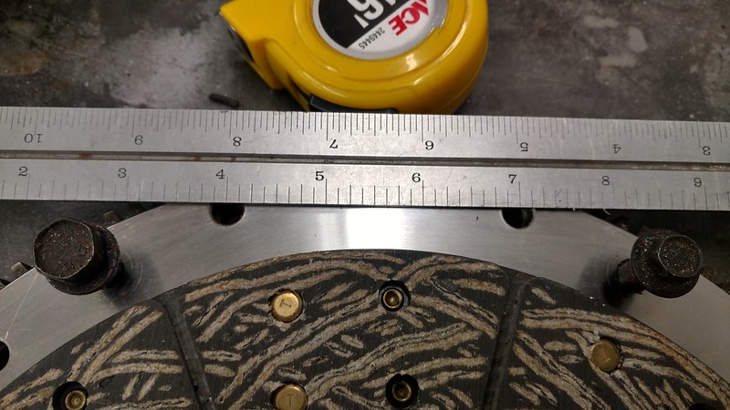
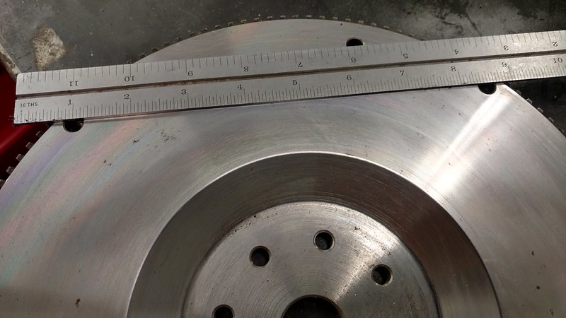
It is close, but might not be "exactly" right. The Ford hole centers are 3.010" for each pair and adjacent bolts are 7.578" between pairs.
The Ford pressure plate also uses a dowel pin between the bolt pairs to center and align the pressure plate. Most of the GM stuff just uses the bolt shank to keep the pressure plate aligned.
|
|

|
motoracer838
|
MAY 28, 09:27 PM
|
|
The funny thing is that it has 3 holes for dowels, but they're oddly located and on a smaller circle than either of the patterns... need to get my hands on a Ranger pressure plate to check it and transfer the dowel location if needed.
The McCleod clutch I have looks to be of their super street series, rated at 550 hp, but (there's always a but...) they have no listing for this size clutch, smallest they show is 10.5" I'll know more tomorrow.
I can relate to not wanting to take the car down for mods, once I got the Indy Hauler up and running, I came up with some really cool ideas for it that would have left it sitting in the shop for years (think C5 Vette with a Blazer skin) that won't do, it's way too much fun to drive as it is, so I came up with a plan to make smaller changes to sharpen it focus, like the front end rework last November, next up this winter is an upgraded engine and rear axle. Yes, I have to many projects...
Joe
|
|
|
|
fieroguru
|
JUN 16, 03:37 PM
|
|
My day job has been far to busy for me to take time off and long haul the 2018 Hot Rod Power Tour... so I decided to earmark the funds for that trip on getting the LS4/F40 Fiero painted...
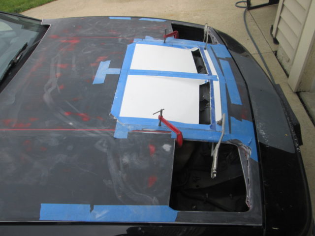
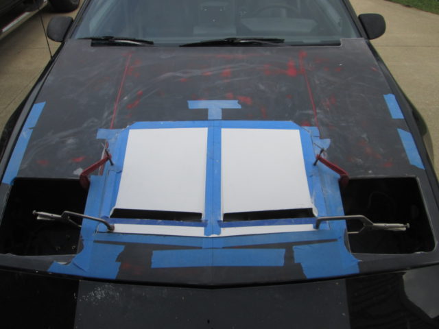
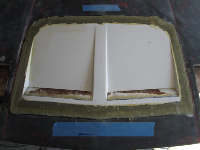
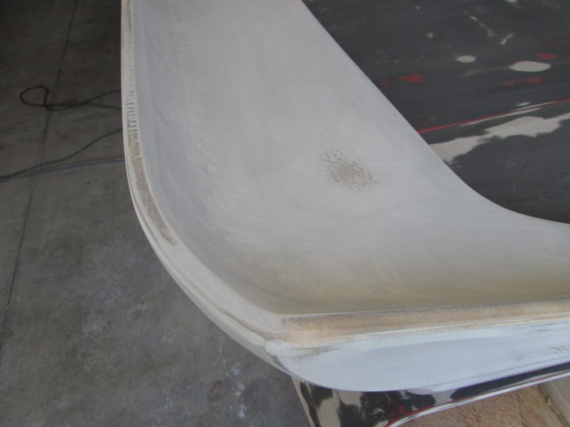
Last year I picked up an entire set of 88 Coupe panels so I can sand and modify the parts while still enjoying my Fiero. I also picked up a mustang convertible whale-tail wing, IMSA side scoops from Sage, TA fender vents from someone on the forum and a mustang STM front hood vent from The Driver. I was able to get the hood decklid sanded, and installed the TA fender vents into the fenders, but that is as far as I got before storing everything in the basement for the winter.
I pulled out the spare hood and STM hood vent and started cutting and fitting. Here is the test fit and final location. The sides of the hood vents start at the center of the headlight covers and flow backwards from there. The vent insert was cut to follow the body lines of the hood, but I cut the side to make them square and 26 1/4" wide to match the leading edge width (this helps with bonding strips). In this picture I have already cut the vents open to make them parallel to the face of the hood and open a little further back.
Here are all the cuts on the hood and the bonding strips (from the hood scraps of SMC). If you notice, nearly all the bonding strips will be hidden by the fiero hood structure. Hindsight 20/20, I could have made the opening in the front a little smaller (I add some pieces back in later).
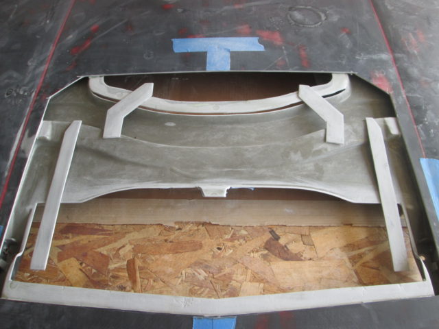
Bonding strips glued in place with SMC Vette Panel Adhesive. Note, had I not trimmed down the sides of the insert to be 26 1/4" wide from front to back, then there would not have been a lip left at the rear for the bonding strip.
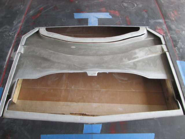
I glued the vent insert onto the bonding strips with SMC Vette Panel Adhesive and let dry. Then I came back with a flapper disk, beveled the seam, applied the first application of fiberglass with SMC resin, and 3 layers of mat with the first piece being about 1/2" wide and progressively wider.
Sanded the first application with 40 grit on the DA and then applied the top layer that is about 2" wide:
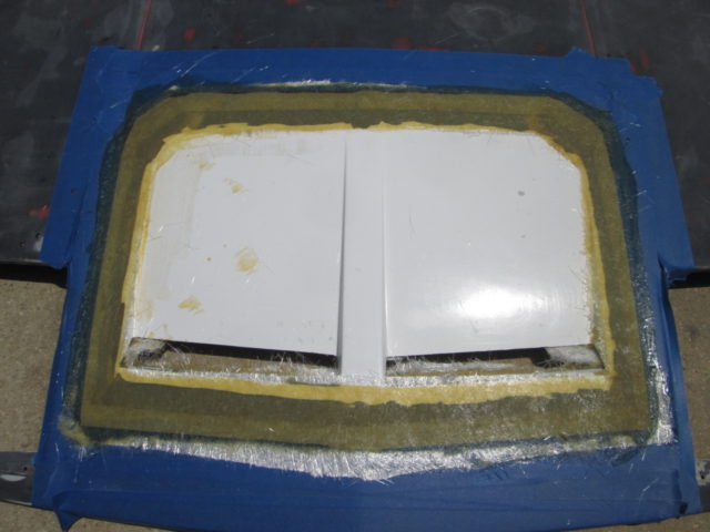
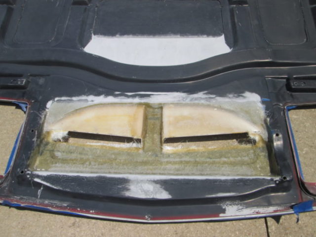
I also did some work to the bottom side. I added in a couple more sections of the original structure I cut out to help close off as many gaps and help reinforce the hood vent to the hood structure. Still more work to be done here, but it is starting to take shape.
While waiting for panel adhesive or resin to dry, I jumped back and forth between the STM hood vent and mustang rear wing. The biggest issue with the rear wing was the different contour between the decklid on the mustang and Fiero - there was nearly a 1/4" gap in some areas. The Fiero one is much flatter. I used the DA to remove material from the mounting bases of the wing which got things a lot closer. Then I finished off the modification by using 2 layers of mat as the base and 2 additional layers in areas that needed more build up. Lots or resin, put some wax paper over the decklid, and quickly bolted the wing down tight to squish everything together and make a new base to the wing. I did each side separately to stay ahead of the resin cure time...
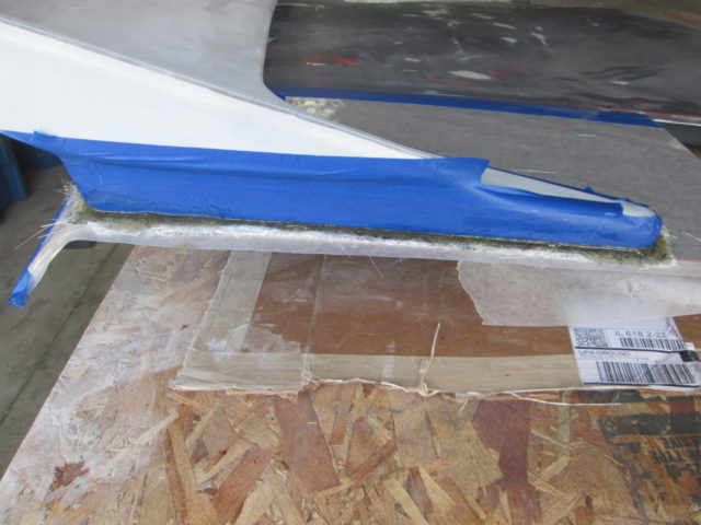
I let it cure for about an hour before doing the other side. Then let it it cure the rest of the afternoon and over night. Block of wood with some 60 grit paper and I sanded back all the excess around the base. Overall the fit is now quite good.
Then I used assorted methods to flatten out the side of the wing, the top lip of the wing and a couple of high spots on the top surface of the wing.
Have I mentioned one of my least favorite activities is sanding...[This message has been edited by fieroguru (edited 06-16-2018).]
|
|
|
|
Jncomutt
|
JUL 04, 10:41 AM
|
|
|
Any chance you have dimensions on your pedal mount plate/bracket? I know its quite a simple piece, but I was looking to fab something up similar ahead of time at work, and won't have the car with me.
|
|
|
|
fieroguru
|
JUL 04, 06:59 PM
|
|
| quote | Originally posted by Jncomutt:
Any chance you have dimensions on your pedal mount plate/bracket? I know its quite a simple piece, but I was looking to fab something up similar ahead of time at work, and won't have the car with me. |
|
Sorry, it was so simple to make, I never took the time to detail it in the drawing. Next time I have it out I detail the bracket.
|
|
|
|
fieroguru
|
JUL 04, 07:55 PM
|
|
Been working on expanding my tool capabilities...
Picked up a 12" combo miter saw and aluminum and steel blades.
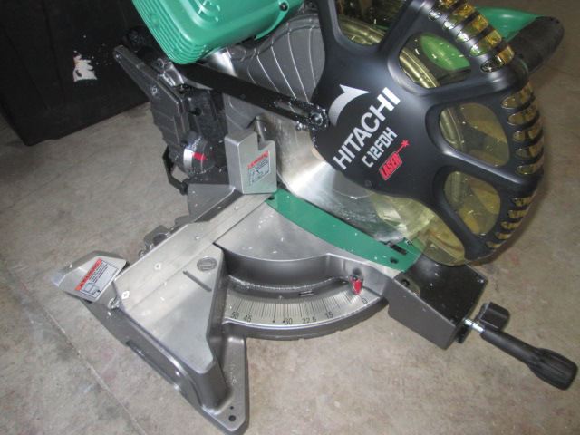
I am rough on power tools and have had good luck with Hitachi grinders and 1/2" drill, so I figured I would give their saw a shot. It is being clearanced at Lowes and the online price is $50 cheaper than at the store (even when you buy on-line & pickup at the store), so it was $199+ tax. I think I am going to drill and tap the bed so I can use the same hold down clamps the mill uses for holding the metal bits for cutting. I did some adjustments to the stop at 90 degrees and squared up the back rests get get everything dialed in. Then I cut some PVC pipe, and put it in the lathe, pretty happy with the precision of the cut overall.
I also picked up a 7" head spacer for the mill.
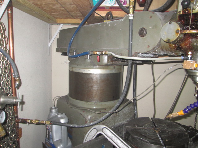
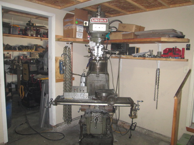
With this spacer, I now have 24 1/4" between the spindle and the table. To drill the coolant passages for the LS water manifold, the part is roughly 12" long and I need to drill two 10 1/2" holes, so I needed 22 1/2" clear and the 17 1/4" I had before the spacer was an issue. Now I can drill those holes entirely on the mill vs. doing the first 6" on the mill and finishing the process with the 1/2" hand drill and drill shaft bushings.
|
|
|
|
Syn
|
JUL 05, 04:54 PM
|
|
|
Is anyone else having issue with the pictures loading?
|
|
|
|