|
| LS4 / F40 swap - fieroguru (Page 13/216) |

|
Isolde
|
MAR 02, 06:39 PM
|
|
| quote | Originally posted by fieroguru:
You can't mill the crank side. The original spacer has a recessed pocket for the crank flange to slide into, then it steps down to allow for the crankshaft flange extension on the other side. The crank flange is somewhere around .380" deep and the spacer was .417 thick (not counting the flange extension). If you take material off the back side, the crank flange will bottom out before the spacer is seated. Take it off the front side and there will only be a couple of thousandth's of material left...
The use of the pilot bearing based flywheel flange isn't anything new, GM has used them before. |
|
Adding the pocket is easy to machine. Even with the sunken taper. I could do that in a couple of hours, no sweat.
The alternative is lathing the male side to keep it's register, then lathing the taper down a matching 0.200"
Either way, the result is the same.
Point is, eventually, you'll find it's necessary to keep BOTH registers. I learned the hard way.
|
|
|
|
fieroguru
|
MAR 02, 07:58 PM
|
|
| quote | Originally posted by Isolde:
Adding the pocket is easy to machine. Even with the sunken taper. I could do that in a couple of hours, no sweat.
The alternative is lathing the male side to keep it's register, then lathing the taper down a matching 0.200"
Either way, the result is the same.
Point is, eventually, you'll find it's necessary to keep BOTH registers. I learned the hard way. |
|
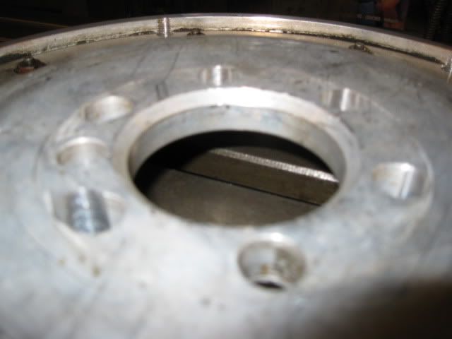
The ID of the GM crank spacer is within .002" of the OD on the extension shaft. Regardless of which side the material is removed from, once the spacer thickness is less than about .380", the remaining material is only .001" thick and will rely on the crankshaft snout for all its support. With the .200 spacer thickness, the remaining portion of the crankshaft flange is only protruding about .156" and due to the .001" thick sleeve very little support happens any further out. My flywheel has a clearance taper on the back side that is .133" deep, so only the portion of the cranshaft protruding more than .133" or about .023" is available to actually support the flywheel. With that little of overlap, in the event the crankshaft bolts sheared off, the flywheel will not be contained within the bellhousing... that was my concern.
So instead of relying on this .023" of overlap, I chose to extend the crank flange surface another .273" via the pilot hole in the crankshaft. This is the same practice GM used with the 2.5's in all their various applications (GM and otherwise). The crankshafts had a removable pilot bushing that contained the flywheel flange (not the bolt pattern, just the lip for the flywheel to center upon) and depending on the application and flywheel used, these bushings changed. If it was good enough for GM, then I do not think the concept is fundamentally flawed.
Once I have everything bolted down and properly torqued, then I will take the time to dial indicate the flywheel assembly to ensure any run out is in the acceptable range. Once that passes, then I will have it checked for the proper neutral balance and balanced if needed. If I run into issue with either of these steps, then I will just send the whole flywheel package off to be remade as a single custom aluminum flywheel and eliminate the need for the flexplate and spacer entirely.
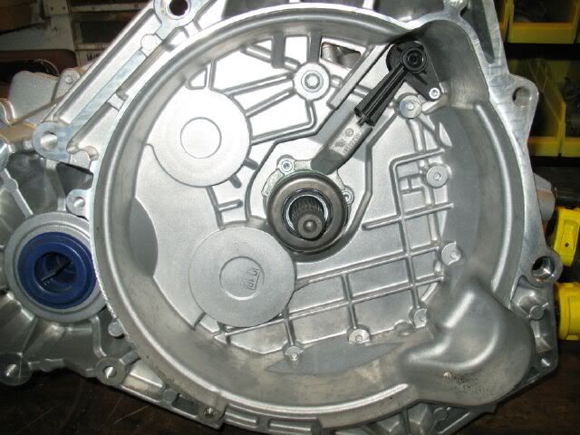
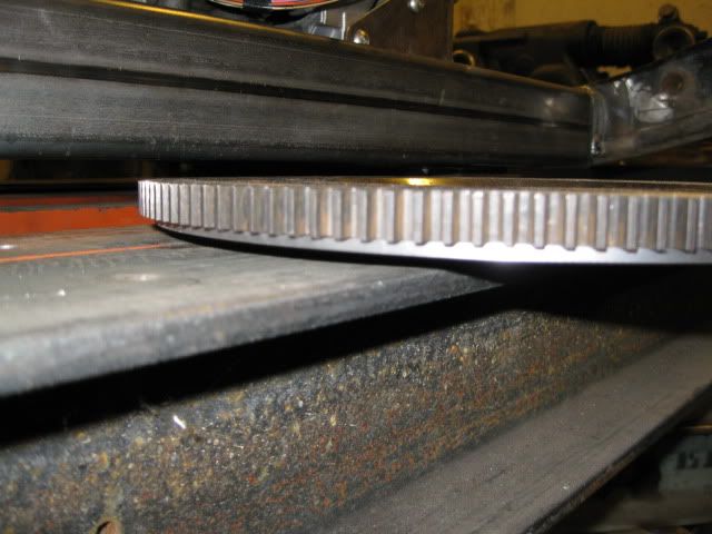
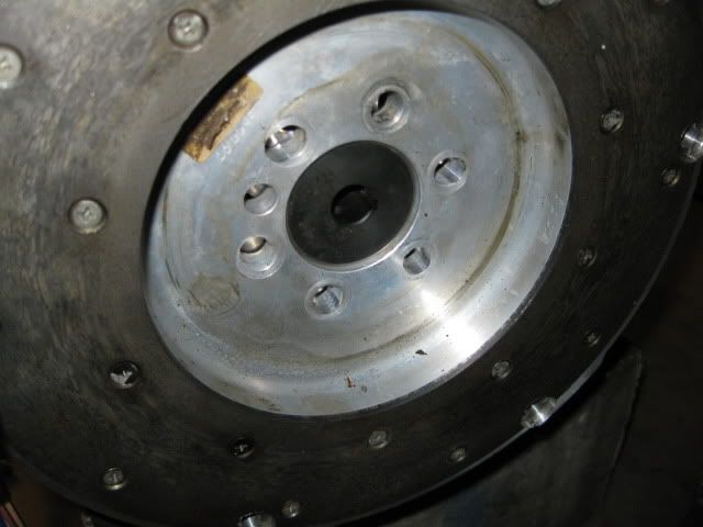
Here is a pic of the backside of my flywheel:
And with it installed on the pilot bushing:
|
|
|
|
dobey
|
MAR 02, 08:38 PM
|
|
Nice shiny new parts! Even those exhaust gaskets look good.
I don't think I ever asked, but are you opening up the heads any? I know you were wanting to rev the engine pretty high, but I don't think you're changing the lifters since you want to keep the DoD, and they limit you to about 6200 RPM. But I was still wondering if you're doing any port work on the heads to let them breathe a little better.
|
|
|
|
fieroguru
|
MAR 03, 11:44 AM
|
|
| quote | Originally posted by dobey:
I don't think I ever asked, but are you opening up the heads any? I know you were wanting to rev the engine pretty high, but I don't think you're changing the lifters since you want to keep the DoD, and they limit you to about 6200 RPM. But I was still wondering if you're doing any port work on the heads to let them breathe a little better. |
|
I am planning to keep the heads stock for now. After it is up and running/tuned and dyno'd I may look into having them CNC ported and milled to bump the compression. As for the DoD lifters, I plan to see how tough/fragile they really are and plan to set my rev limiter around 6800 rpm. Once I frag one, I will probably just convert engine from DoD to VVT with some conventional lifters and play with that setup, but supposedly the VVT hardware will not clear the LS4 water pump. I think there is room to space the water pump away from the block some, but do not know how much room that setup would actually need.
|
|
|
|
fieroguru
|
MAR 03, 05:52 PM
|
|
The flywheel bolts came in today!
I was able to rough mockup the flywheel/clutch/pressure plate assembly today. The spacers are 1" in length and with the recesssed boss, they are .865" above the clutch face on the flywheel. Stock is .820" and I will probably be shooting for .750" once I mill them down. But they are close enough to start the mockup process:
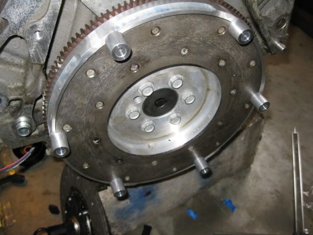

The face of the flywheel is about 1.675" from the bellhousing face and the splines on the clutch disk start at the clutch face and protrude further into the transmission. Since the splines on the transmission start at 1.502" and go further into the transmission, the splines should extend .173" past the spline hub on the clutch disk... this leaves plenty of room for fine tuning the depth of the flywheel w/o worry of spline engagement less than 100%.
The depth of the F40 bellhousing is about 3.505" and the pressure plate is currently protruding 3.635" from the bellhousing of the engine. So, right now the flywheel/clutch/pressure plate assy is about .130" too tall to fit within the transmission. Once the spacers are milled down, I will gain .115" of clearance taking the interferance down to .015". I want to have at least .0625" (1/16") clearance between the presssure plate and the transmission case so the .200" spacer needs to be cut down another .078" to allow the pressure plate to fit... and that will be a fairly simple fix. Pulling the flywheel .078" closer to the engine will still leave the splines of the input shaft protruding .095" past the clutch hub and still retain 100% spline engagement.
The pressure plate fingers are currently protruding 3.332". Milling the spacers and making the crank spacer thinner will make them somewhere around 3.0 to 3.1". The HTOB range of motion is from 2.675" to 3.582 with the midpoint of travel being 3.129"... so everthing looks like it will work just fine.
Now I need to make the spacer thinner, mill the pressure plate spacers and put it all back together to ensure everything clears.[This message has been edited by fieroguru (edited 03-03-2011).]
|
|
|
|
Isolde
|
MAR 03, 10:21 PM
|
|
|
So, is it correct to think you're relying on your black-looking pilot bushing adapter thing INSTEAD of that lip you milled off?
|
|
|
|
fieroguru
|
MAR 04, 06:38 AM
|
|
| quote | Originally posted by Isolde:
So, is it correct to think you're relying on your black-looking pilot bushing adapter thing INSTEAD of that lip you milled off? |
|
For the most part, yes. Making the spacer thinner slides the flywheel more on the crank and less on the pilot bushing, but the vast majority of the flywheel thickness is on the pilot bushing.[This message has been edited by fieroguru (edited 03-04-2011).]
|
|
|
|
fieroguru
|
MAR 05, 08:09 PM
|
|
|
|
|
fieroguru
|
MAR 06, 06:45 PM
|
|
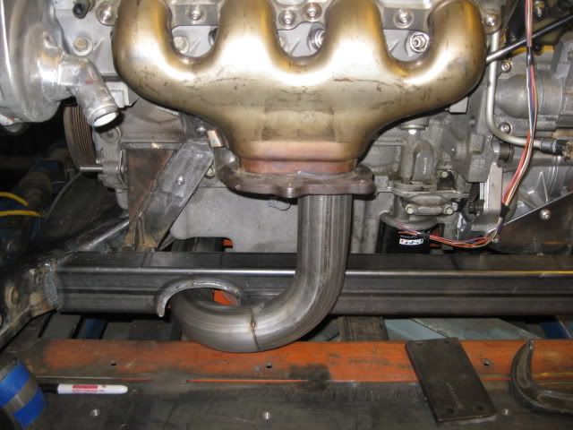
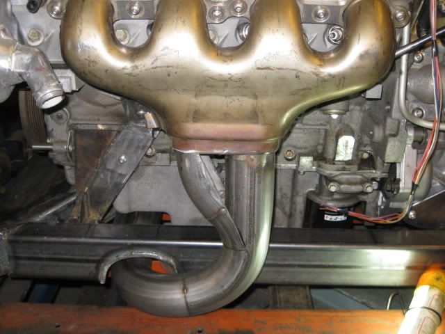
Gotta love hacking up perfectly good manifolds:

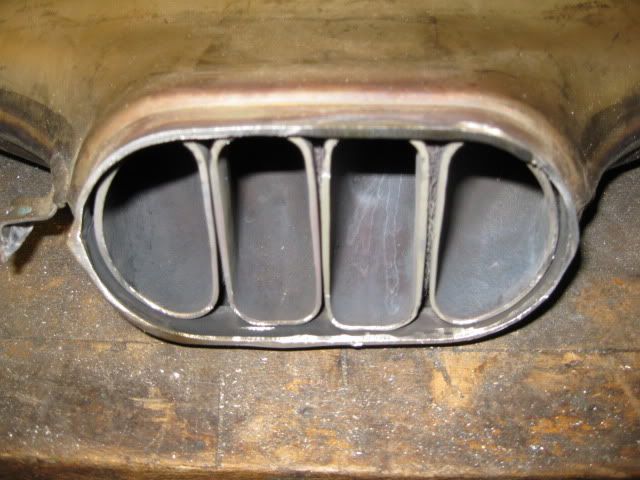
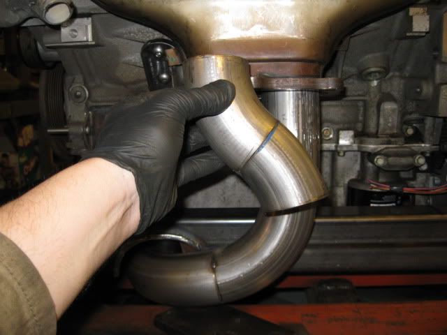
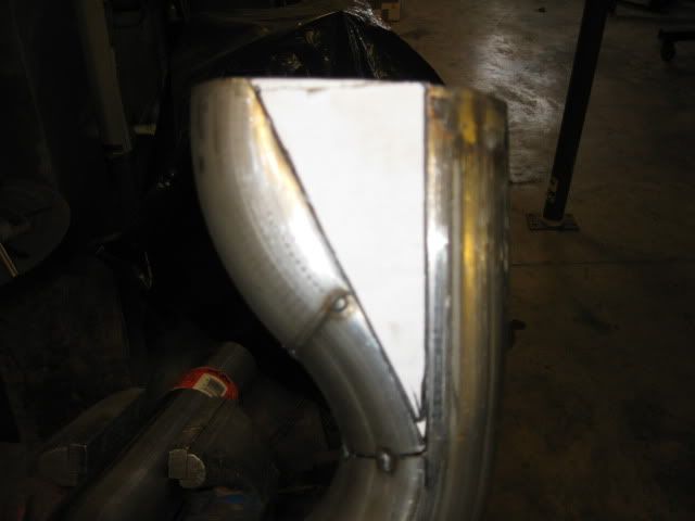
Test fitting the sections:

Template for the triangles:
I took some of the stainless 16ga exhaust tubing, flattened it and sheared it to make the triangles and then tacked them in place:
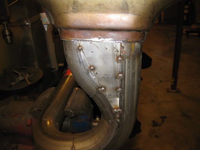
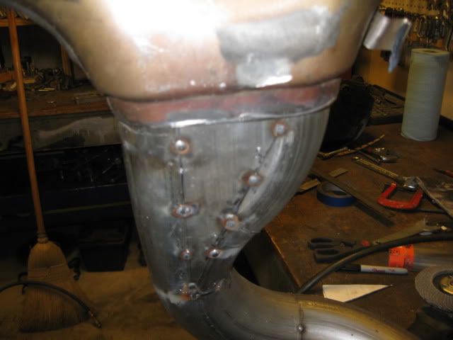
Now the front side just needs to be fully welded and smoothed:
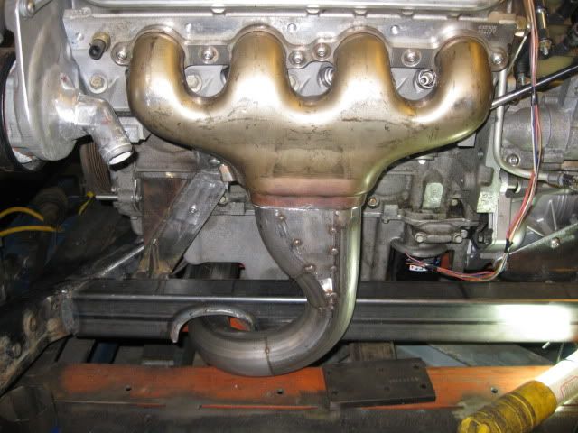
In case you are wondering why I didn't use the factory bolt on flanges... mainly because the other half of the flanges cost $74 + the cost of the copper gaskets ($20) and the only aftermarket flanges available are mild steel. I want a 100% stainless exhaust and removing the flanges will save some weight and clean up the overall look.
|
|
|
|
dobey
|
MAR 06, 08:48 PM
|
|
| quote | Originally posted by fieroguru:
In case you are wondering why I didn't use the factory bolt on flanges... mainly because the other half of the flanges cost $74 + the cost of the copper gaskets ($20) and the only aftermarket flanges available are mild steel. I want a 100% stainless exhaust and removing the flanges will save some weight and clean up the overall look. |
|
I'm a bit surprised you didn't just make a flange for the piping side, and buy only the gaskets. But looking good. Can't wait until I'm tacking up the exhaust for mine. 
|
|
|
|