
 
     |
| LS4 / F40 swap - fieroguru (Page 100/216) |

|
fieroguru
|
SEP 12, 07:33 PM
|
|
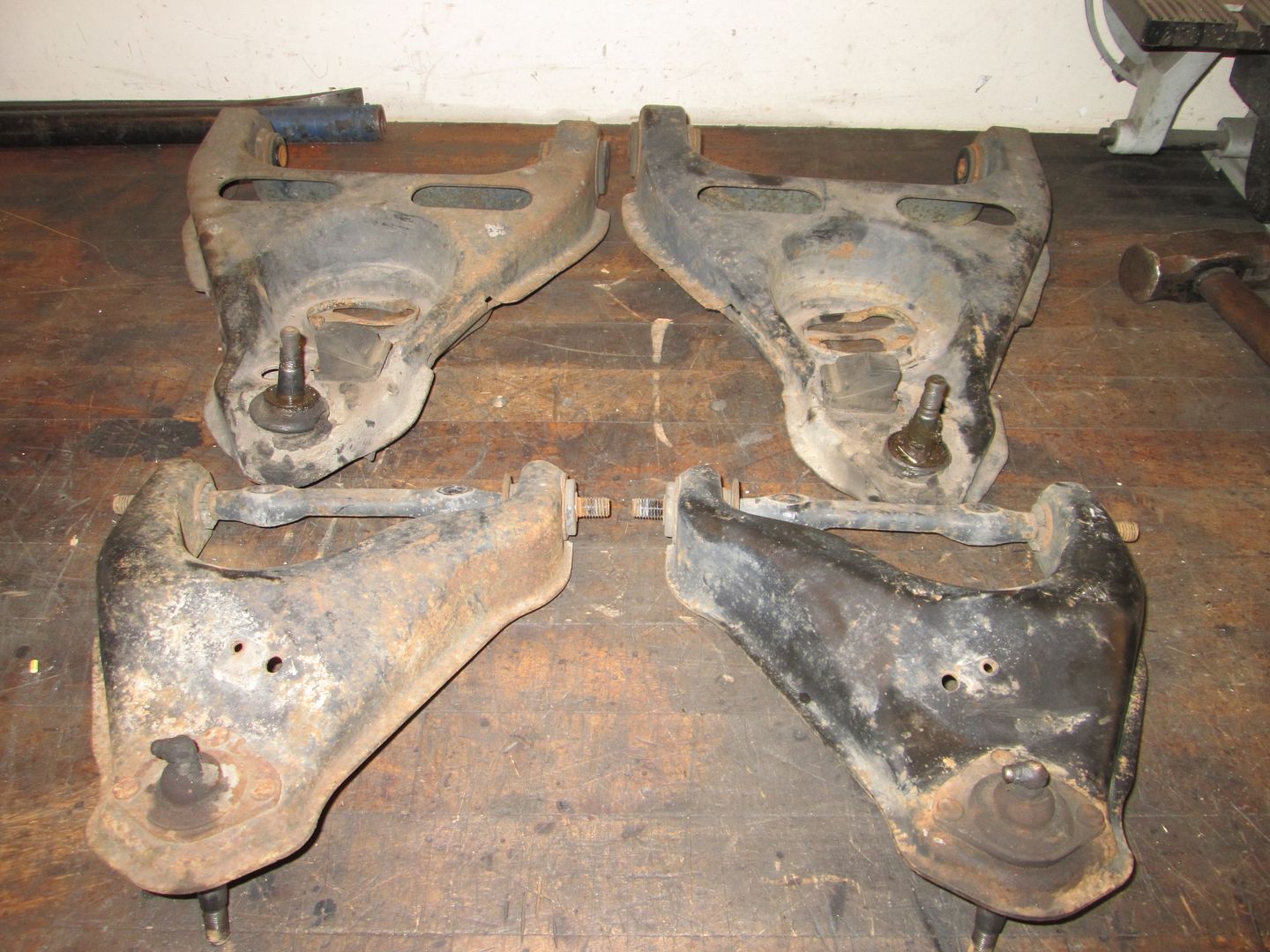
Tore the DS suspension apart this evening:
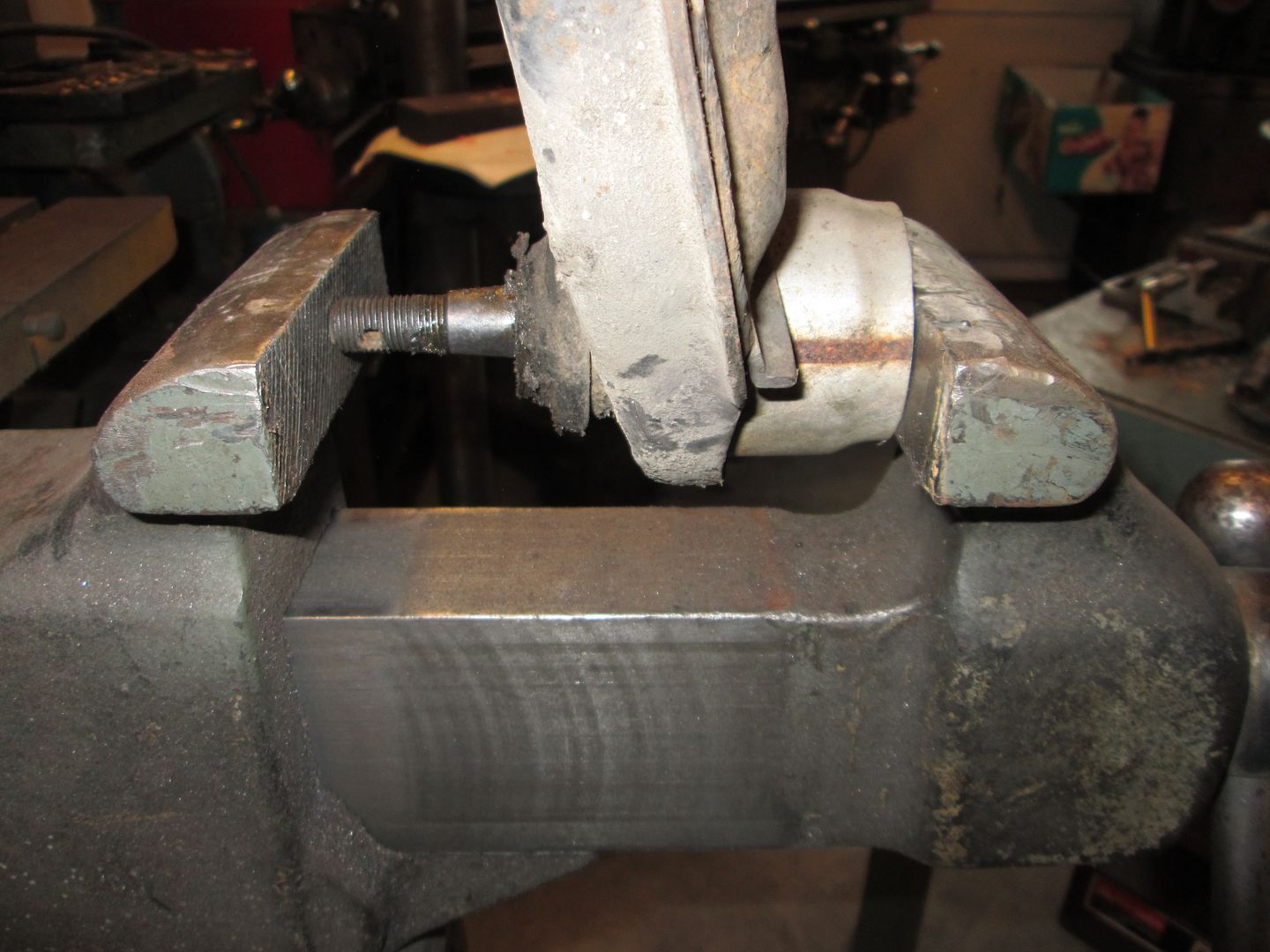
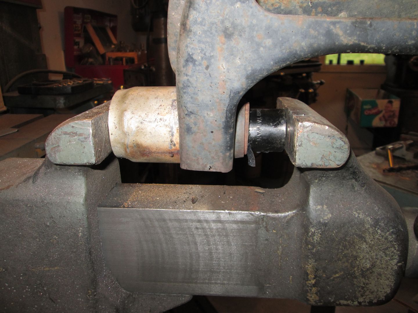
To press the lower ball joints out, I used a short section of exhaust pipe and my vice:
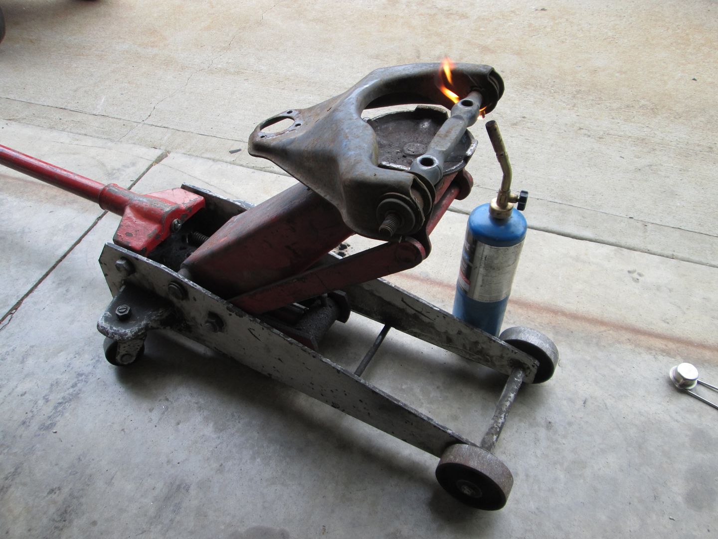
To remove the rubber bushings w/o much smoke or mess. Use a propane torch to heat the bushing sleeve while moving the heat around the sleeve about 3 minutes:
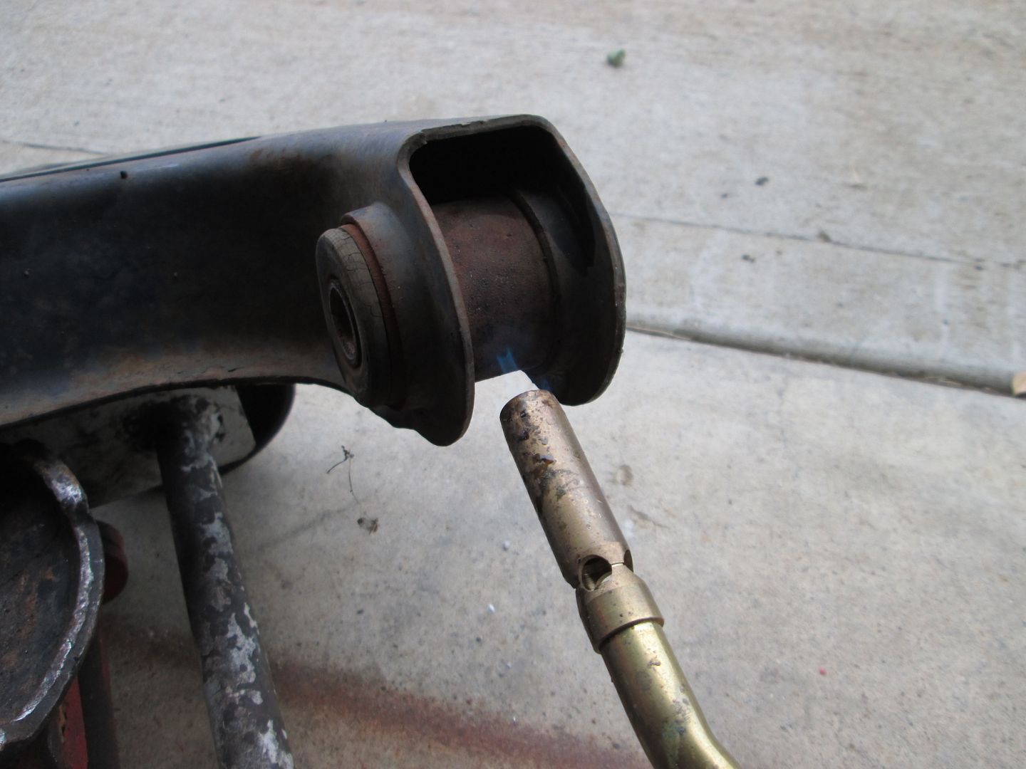
You want to hear the bushing start popping and see the large flange end start pulling away from the sleeve like this:
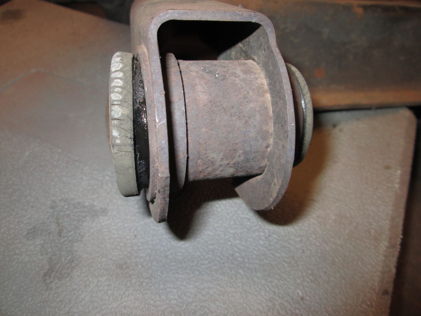
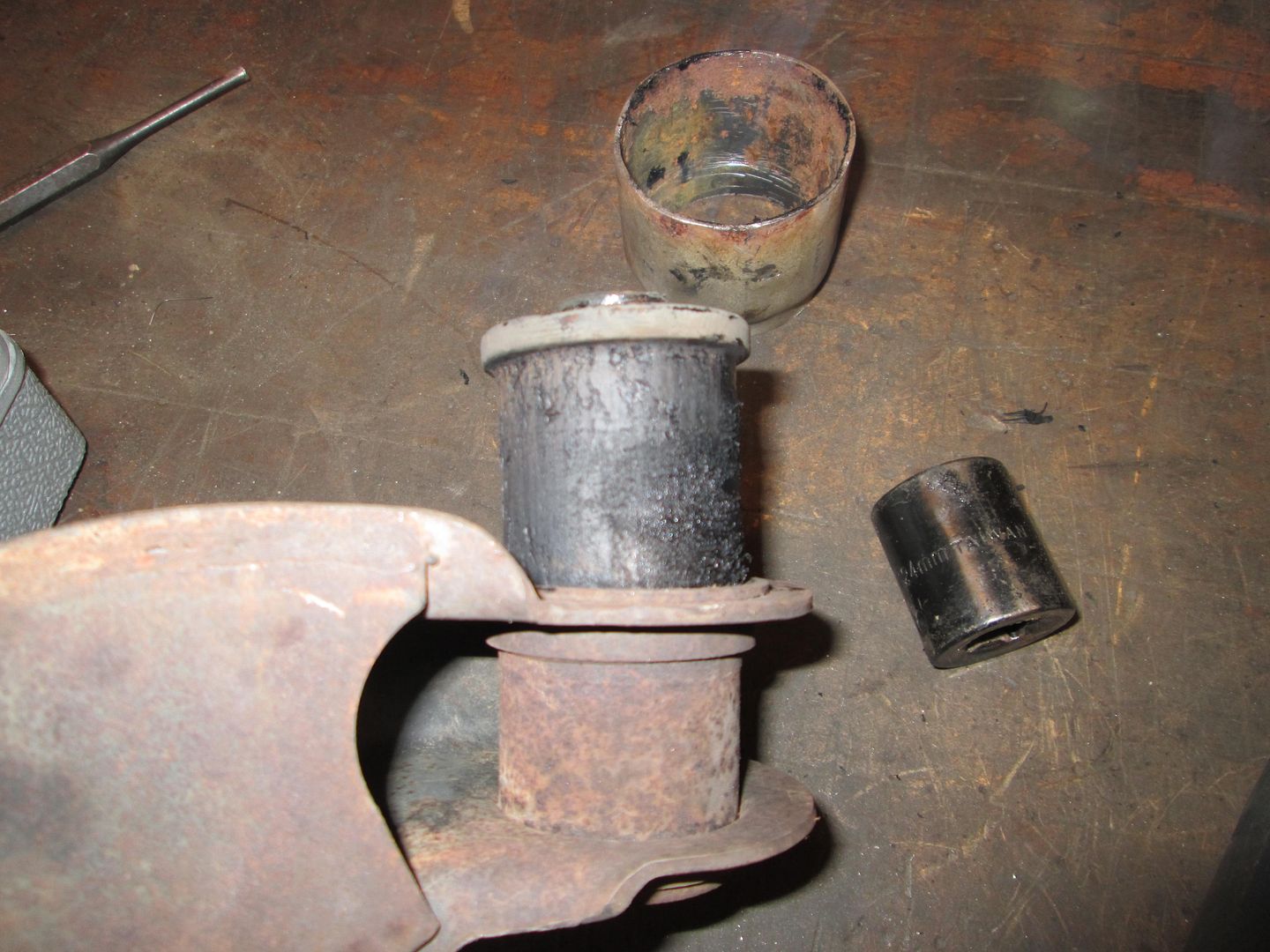
Now back to the vice with the same piece of exhaust pipe on the large end and a decent size socket on the other. Use the vice to press the bushing out. It slides out w/o much fuss since the majority of the outer surface has started to melt:
The removed bushing looks like this:
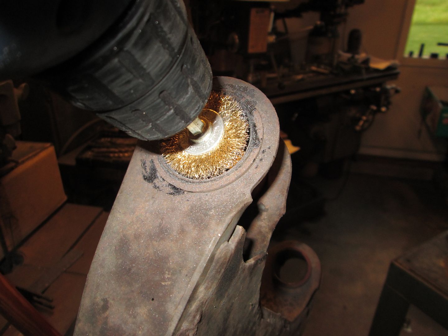
Then use a round wire brush on a drill to clean the ID of the sleeves:

On the upper a-arm, just grind down the tops of the rivets and pop out the ball joint. I ran out of propane before getting the rubber bushings off. So this is how I left it for this evening:

|
|
|
|
Will
|
SEP 13, 07:35 AM
|
|
| quote | Originally posted by fieroguru:
To remove the rubber bushings w/o much smoke or mess. Use a propane torch to heat the bushing sleeve while moving the heat around the sleeve about 3 minutes:
You want to hear the bushing start popping and see the large flange end start pulling away from the sleeve like this:
Now back to the vice with the same piece of exhaust pipe on the large end and a decent size socket on the other. Use the vice to press the bushing out. It slides out w/o much fuss since the majority of the outer surface has started to melt:
|
|
My experience has been that if you keep the heat on it, the bushing walks itself right out of the sleeve and you don't have to push on it at all.
|
|
|
|
Will
|
SEP 13, 07:39 AM
|
|
Looks closer to 1.5" OD... still too big.
I have the design for weld in shells to replace the stock bushing sleeves, but any bearing over 1.187 OD doesn't leave enough wall thickness to maintain strength.
|
|
|
|
fieroguru
|
SEP 13, 08:43 AM
|
|
| quote | Originally posted by Will:
My experience has been that if you keep the heat on it, the bushing walks itself right out of the sleeve and you don't have to push on it at all. |
|
I used to do it that way as well. Only downsides is it takes longer and produces a lot more smoke and fumes. This way is faster with less smoke/fumes (3 minutes to heat, 1 minute to press out)... just need to have a large enough vice.
For the upper control arms, I will just heat them till they slide out on their own as the cross shaft doesn't leave much room to press them out.
| quote | Originally posted by Will:
Looks closer to 1.5" OD... still too big.
I have the design for weld in shells to replace the stock bushing sleeves, but any bearing over 1.187 OD doesn't leave enough wall thickness to maintain strength. |
|
The smallest ones they have are 2" OD with the 3/16" sleeve. They do have one that has a .480" center hole and is 1.600" wide. You could likely use them for the control arms if you cut the stock bushing sleeve end off and radius it to fit the larger sleeve and weld it together.
http://currieenterprises.re...ub_cr_id=32380332462[This message has been edited by fieroguru (edited 09-13-2014).]
|
|
|
|
fieroguru
|
SEP 13, 07:32 PM
|
|
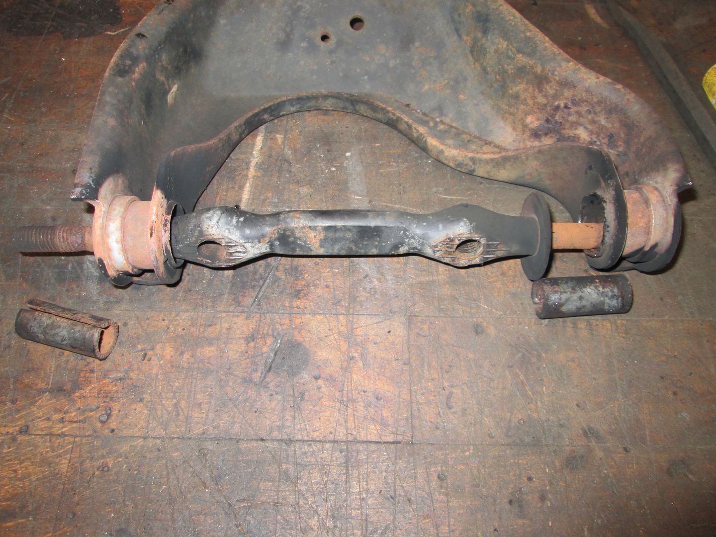
Super busy day...
Here are a couple of pictures of the upper a-arm bushings. They were in need of replacement!
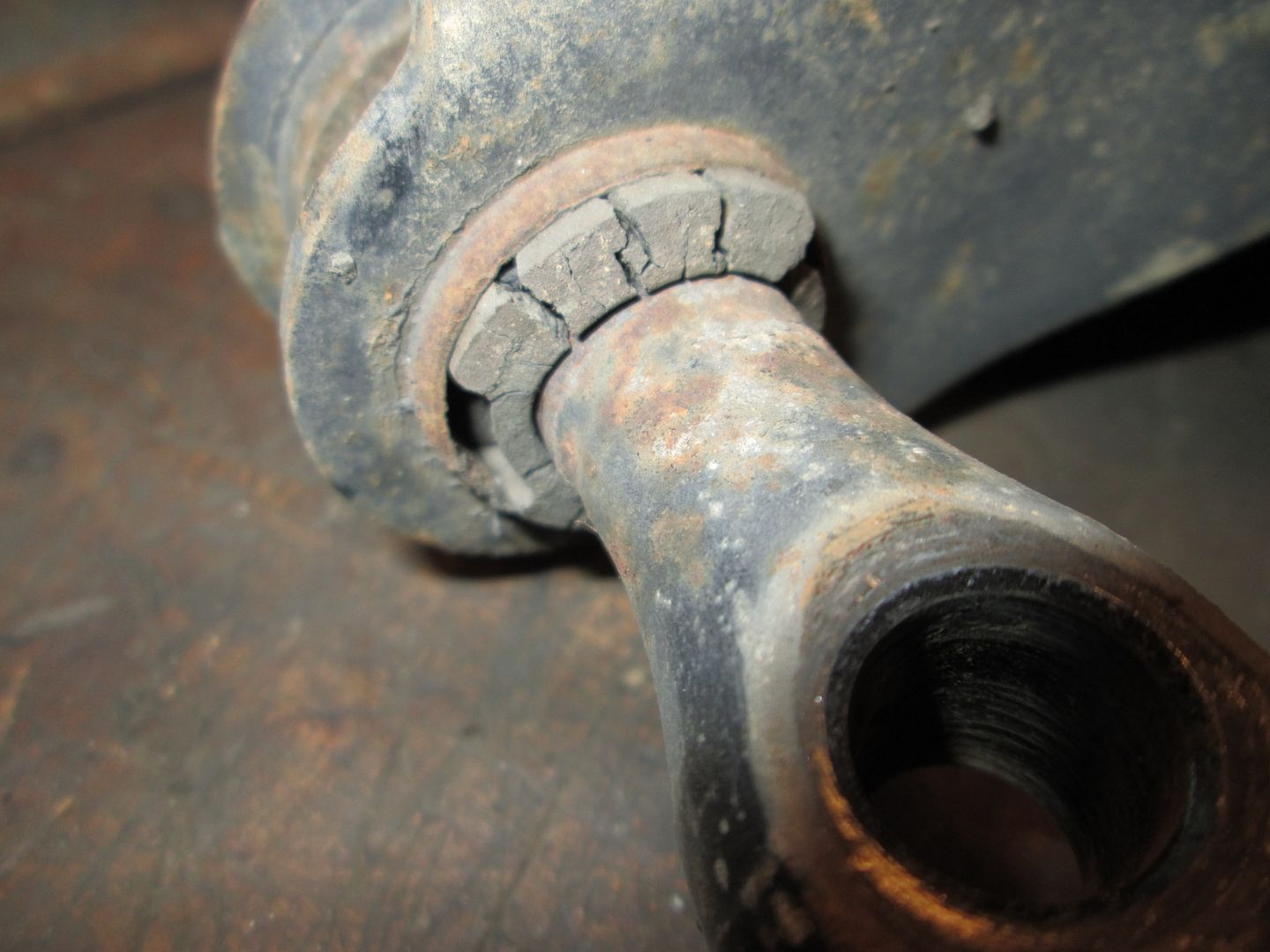

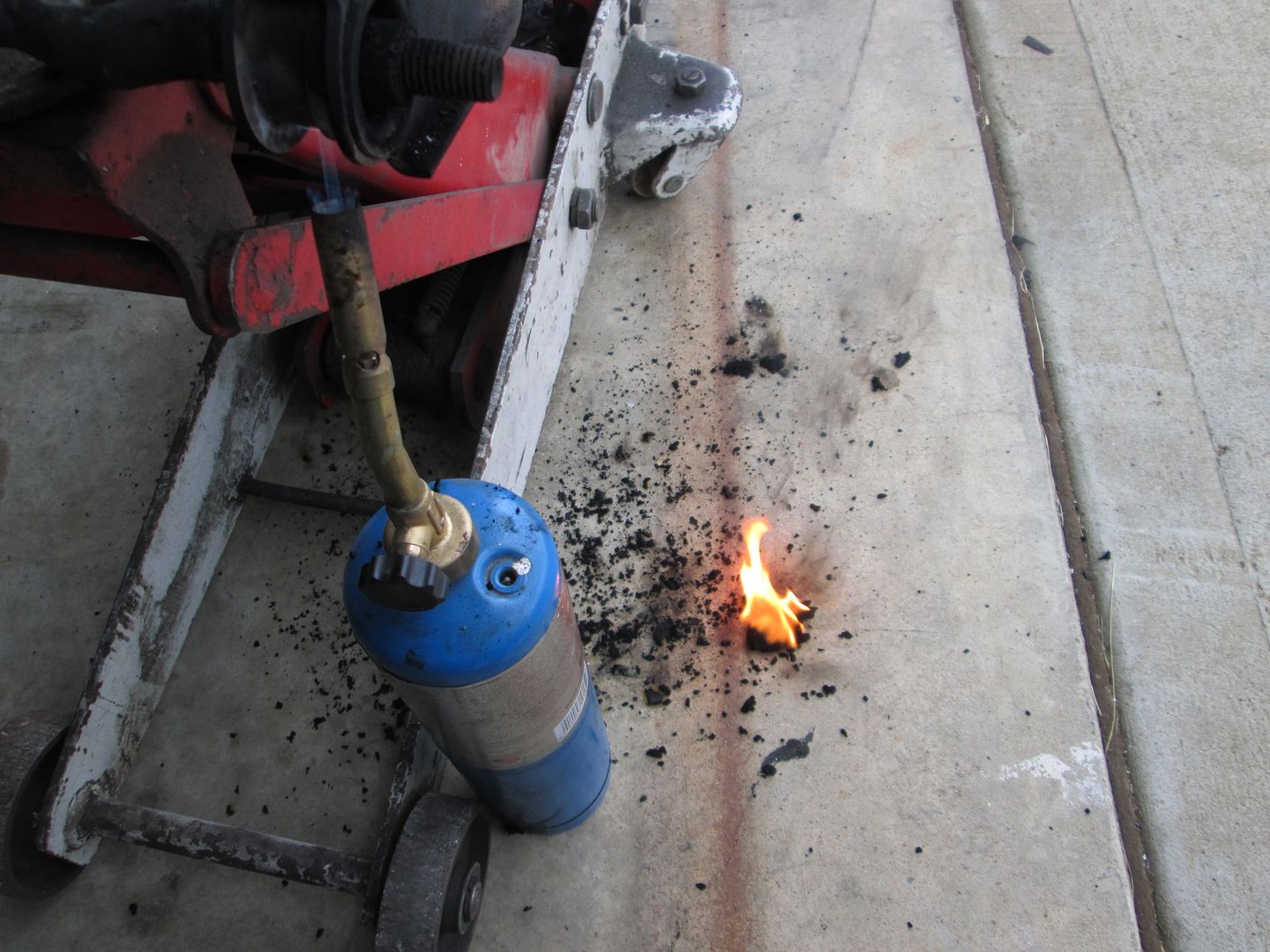
Set the upper a-arms on the jack, set the propane bottle under it and let it burn for about 10 minutes. Lots of smoke/fire, but got the bushings out.
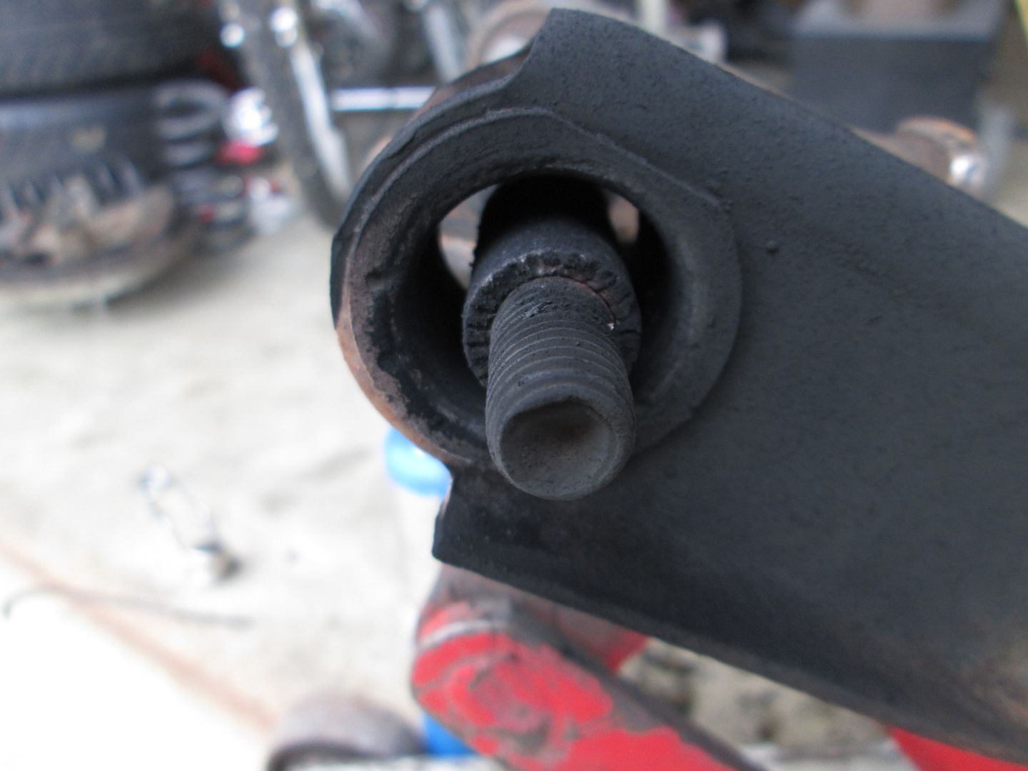
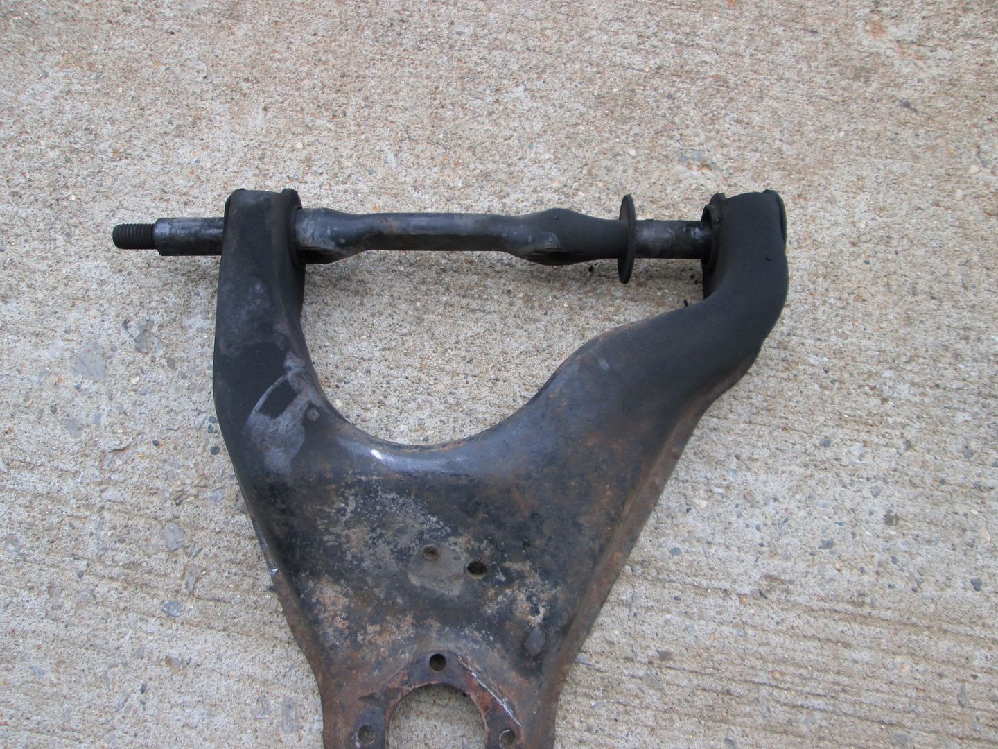
The bushing sleeves were stuck, so I took a chisel and used it to open the seam and spread the sleeve so it would slide off.

Then I wired brushed the upper and lower control arms, washed them in the kitchen sink with dawn, and baked them in the oven at 300 to make sure they were dry.
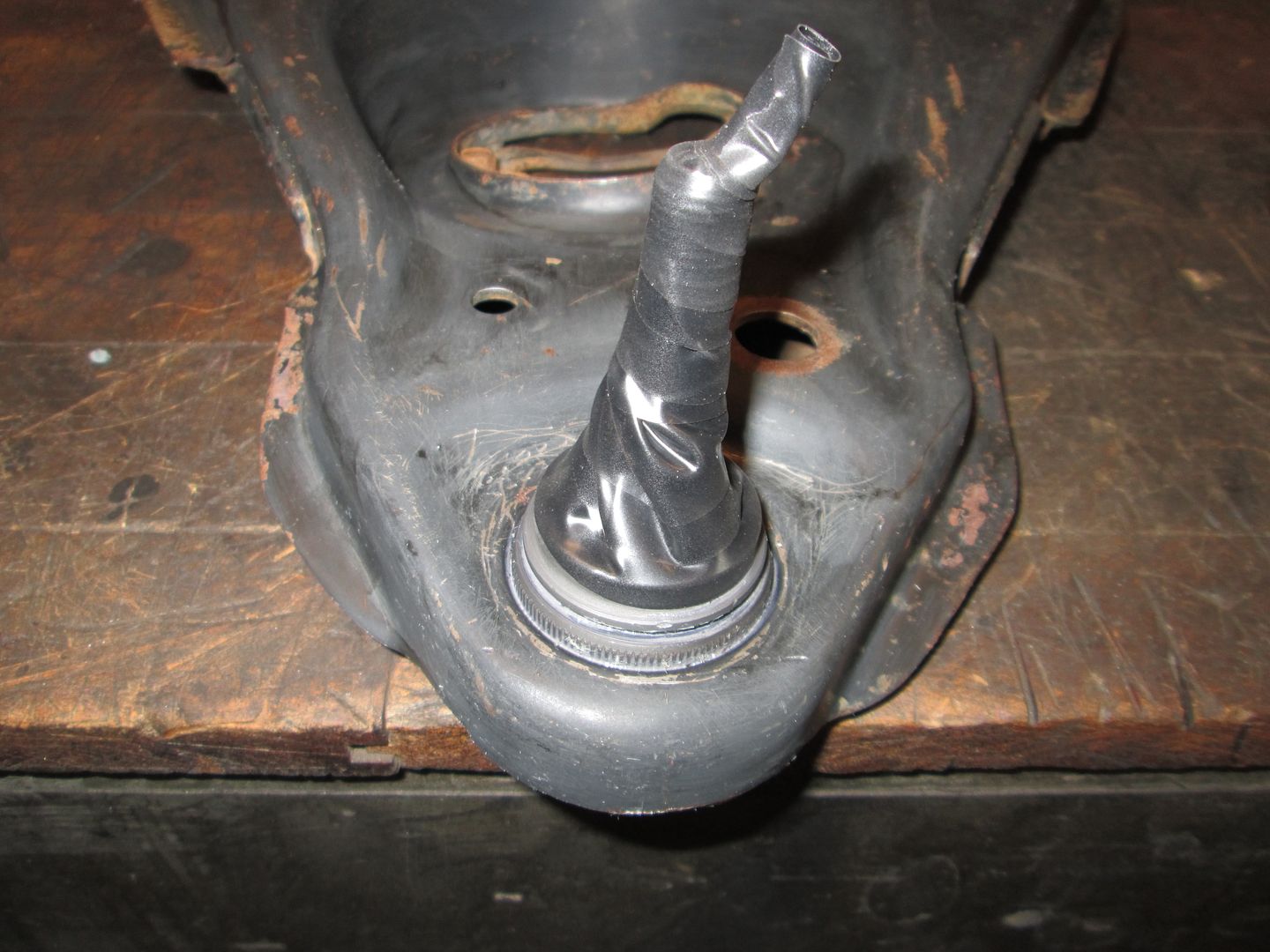
Time to install the lower ball joints... I used a ball joint press for this. They went in much harder that they came out, which is a good thing:
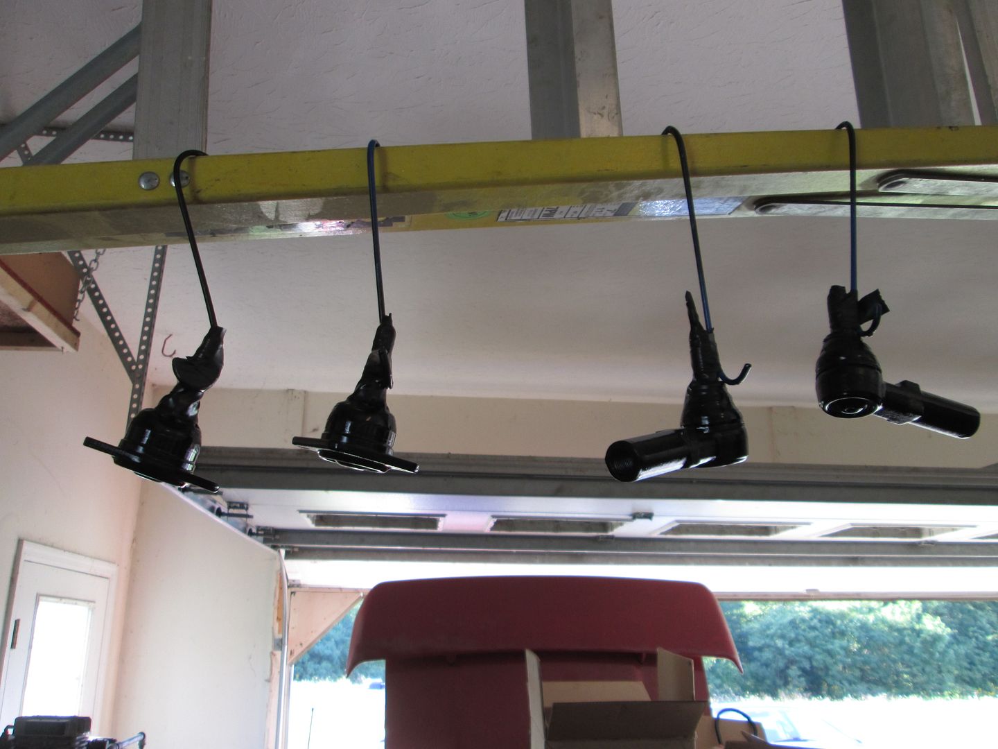
Taped up the ball joints so I can paint the lower a-arms:
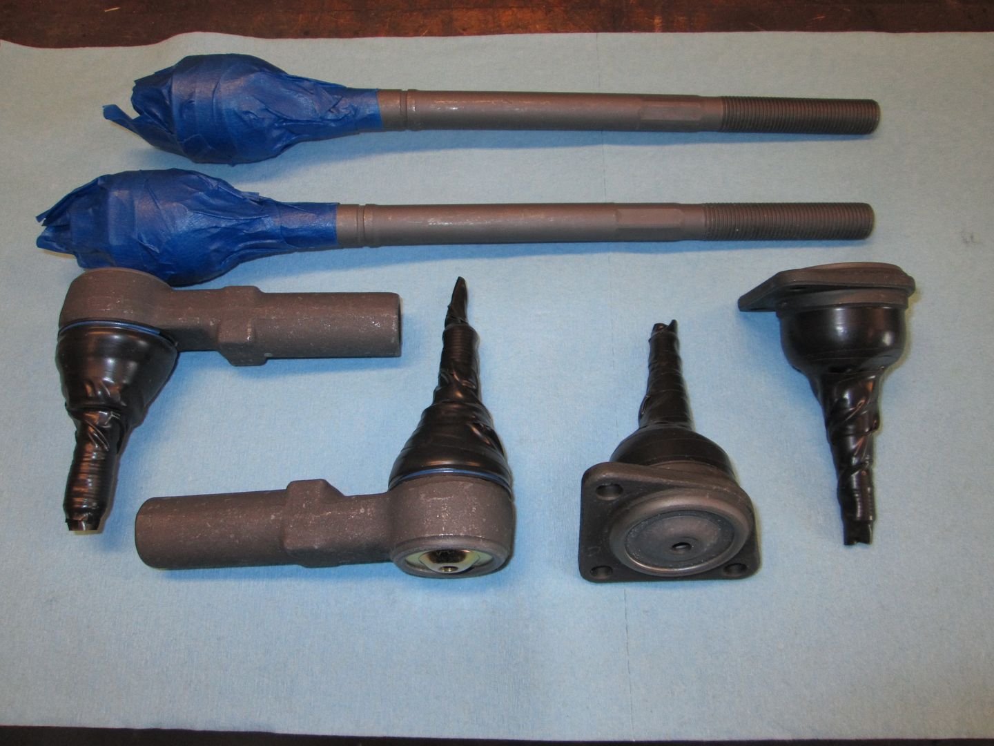
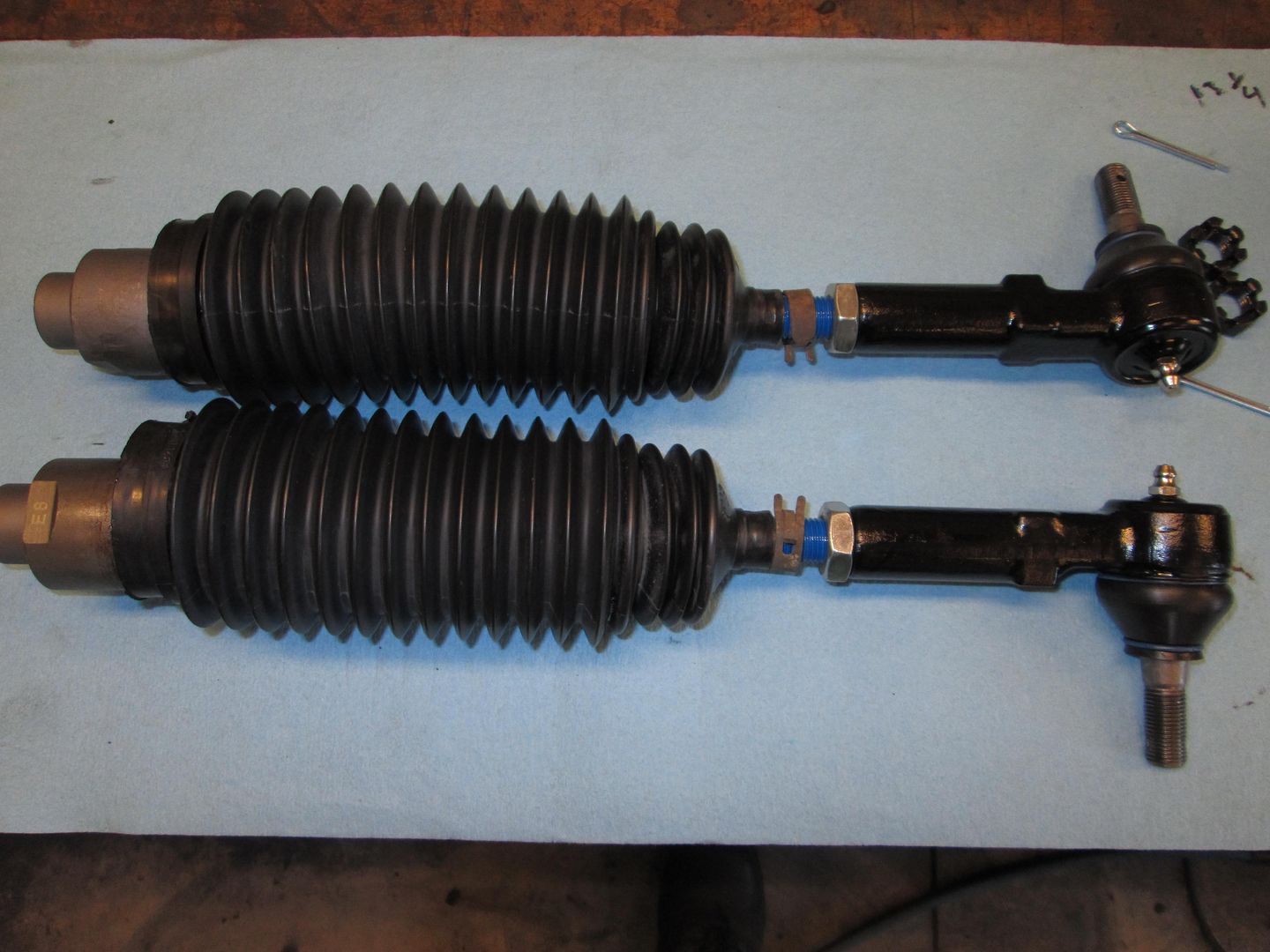
Took the time at this point to also prep the upper ball joints and tie rods for paint as well:
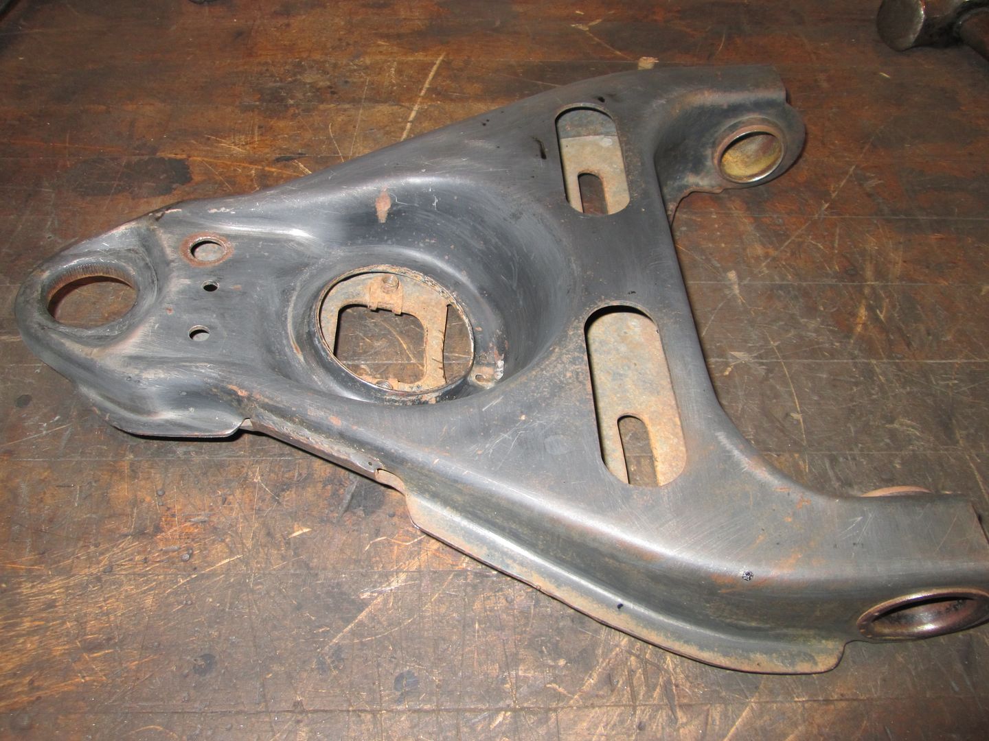
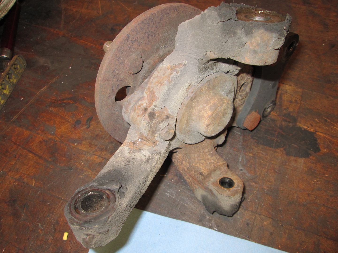
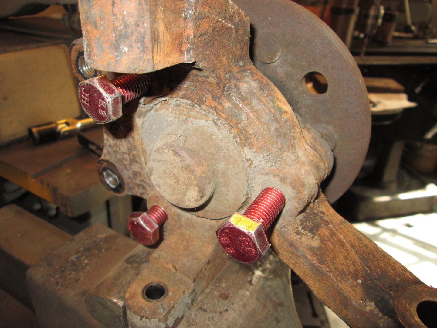
Decided to also disassemble the front uprights for painting too. Here is a before shot:
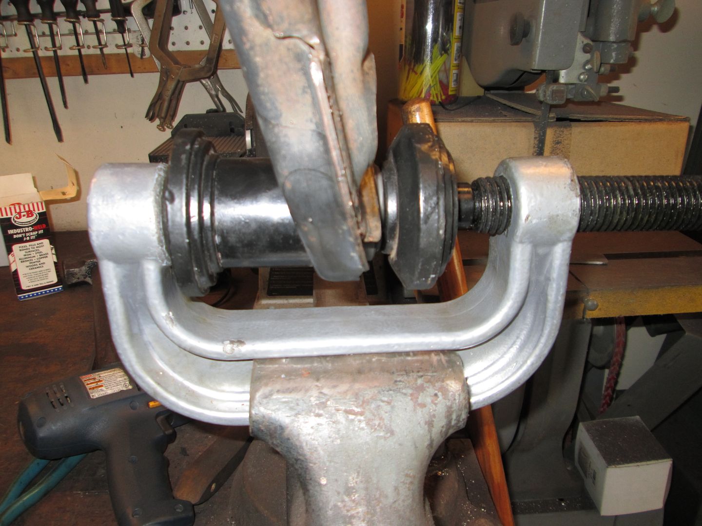
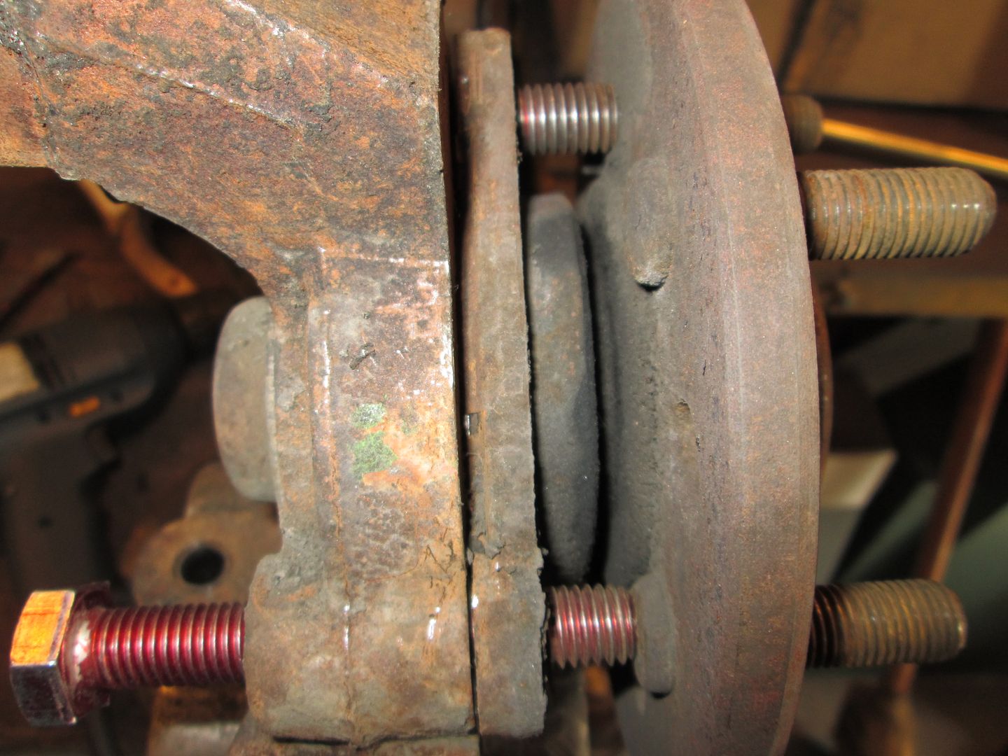
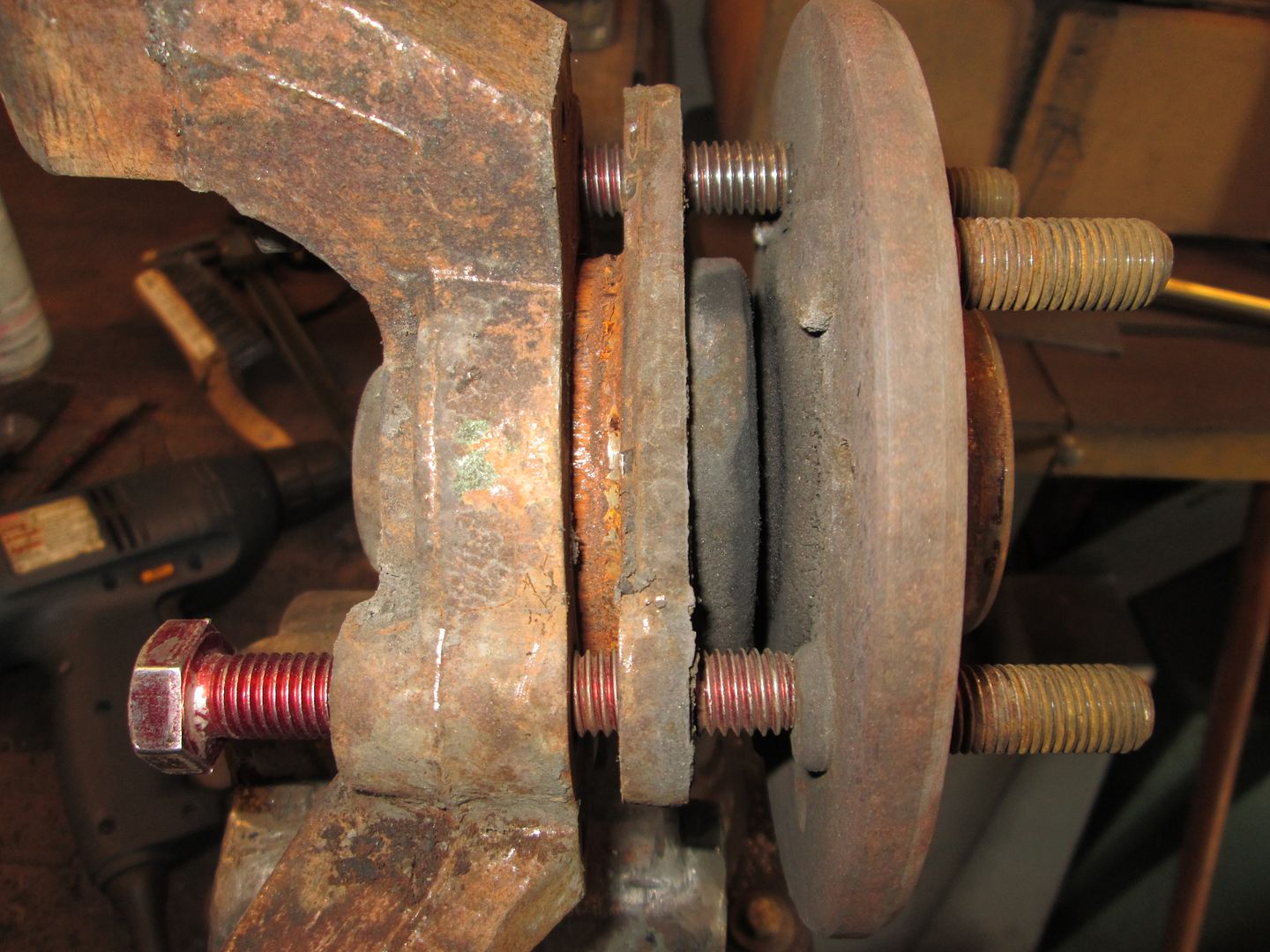
Used a chisel to break the bearing free from the upright (notice the gap):
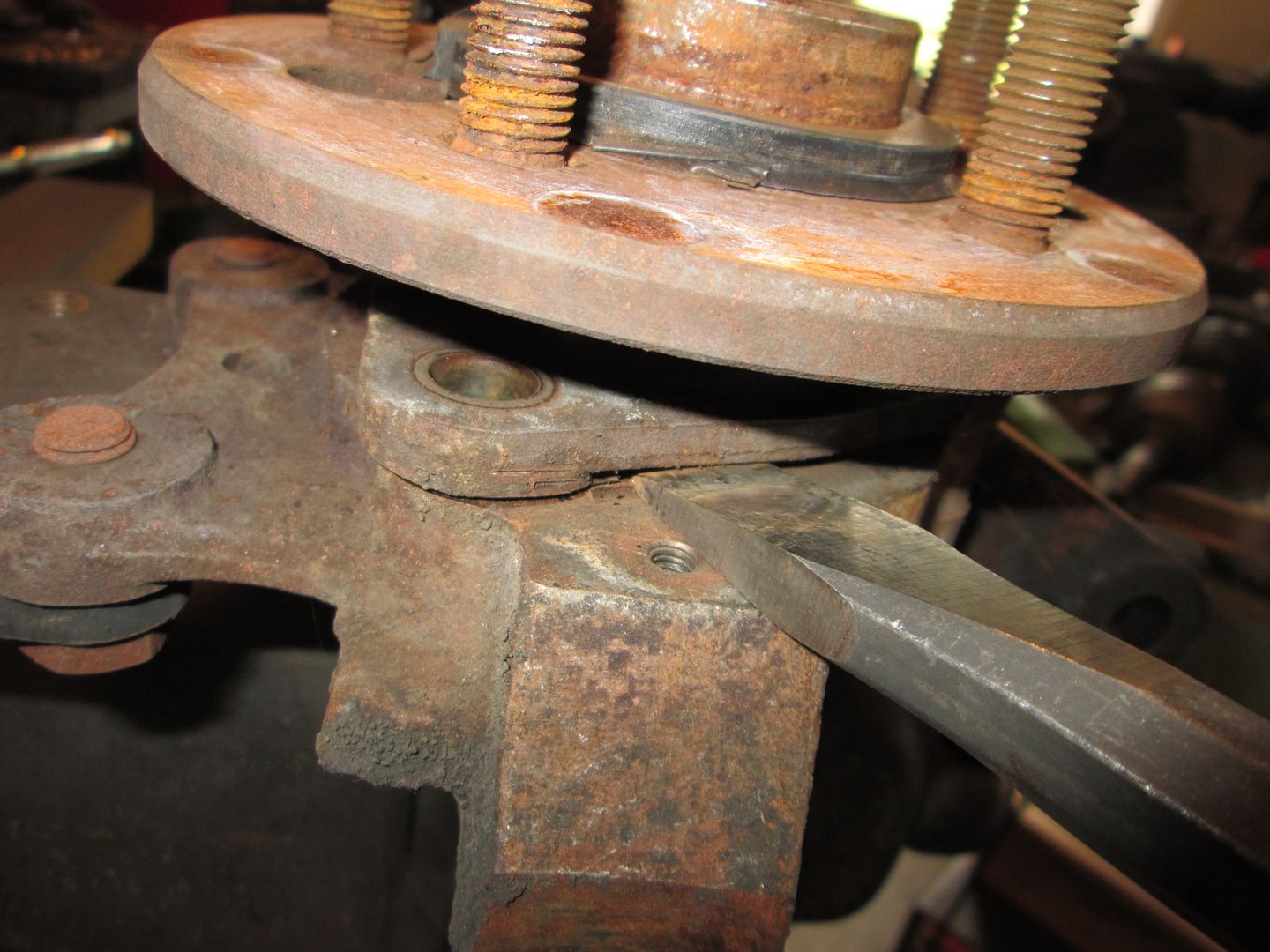
Then used 3 long M12x1.75 bolts to push the bearing the rest of the way out. Once the bolts were touching the backside of the flange, I turned each bolt 1/4 turn at a time as I walked the bearing out.
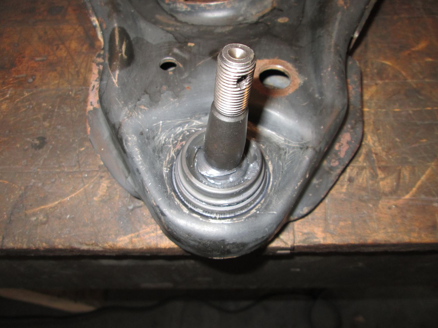
Lots of scraping, wiring brushing, cleaning, oven time, and placed the wheel bearing face on the belt sander:

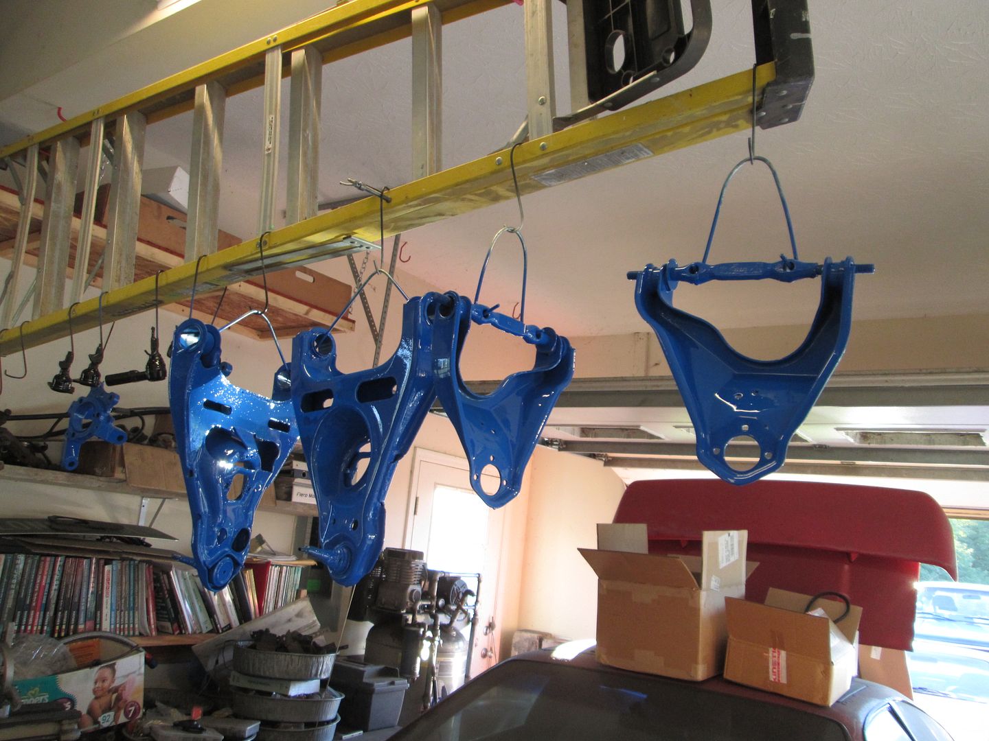
Black parts:
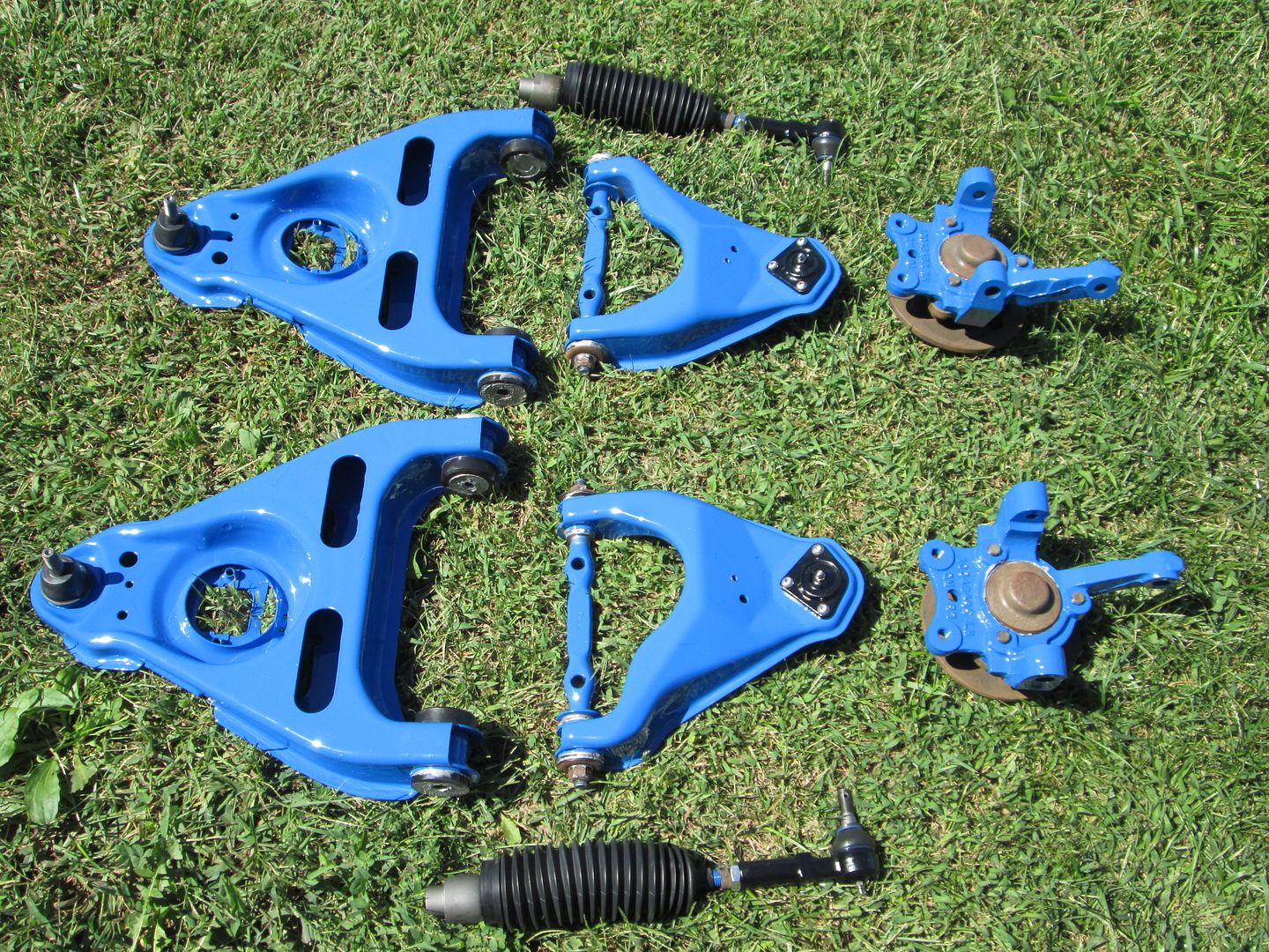
Blue parts:
|
|
|
|
Trinten
|
SEP 13, 10:39 PM
|
|
Looking great! For your upper ball joints, it looks like you unscrewed the grease fittings. I thought maybe you were going to put tape over that whole face where the grease fitting goes, but in the "hanging/drying" pic, it looks like you painted that surface as well without taping it over? Or is it just an illusion, or did you do something else?
|
|
|
|
fieroguru
|
SEP 14, 08:05 AM
|
|
|
The upper and lower ball joints are supplied w/o the grease fittings installed. I wanted them to be fully painted on their exterior and will install the grease fittings today. The holes are pretty small, and most the painting was sprayed at an angle to avoid much paint finding its way into the actual ball joint area.
|
|
|
|
fieroguru
|
SEP 14, 06:58 PM
|
|
Another busy day...
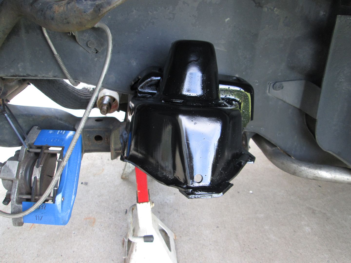
Wire brushed and painted the upper part of the crossmember:
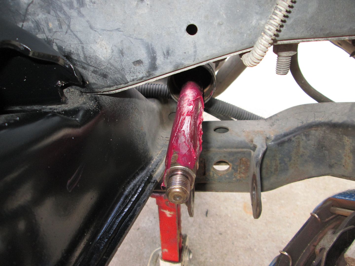
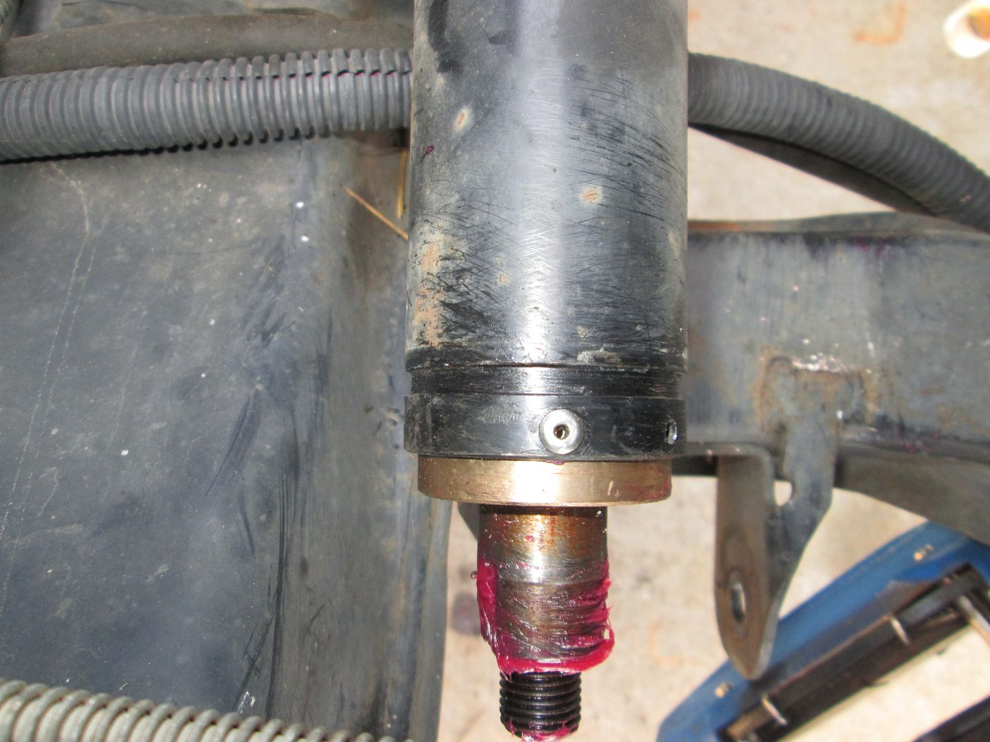
Then greased up the rack shaft, turned it so it was most of the way to the DS, slid the brass bushing into place, drilled a couple of holes and riveted it in place.
Then I started on the reassembly process for the tie rods. Measured the length of one of the old ones and built the new ones to the same length just as a starting point. I even took the rack books and brushed them with dawn to clean them up as well:

Then after lots of assembly, bushing installation, and anti-sieze:
More assembly:
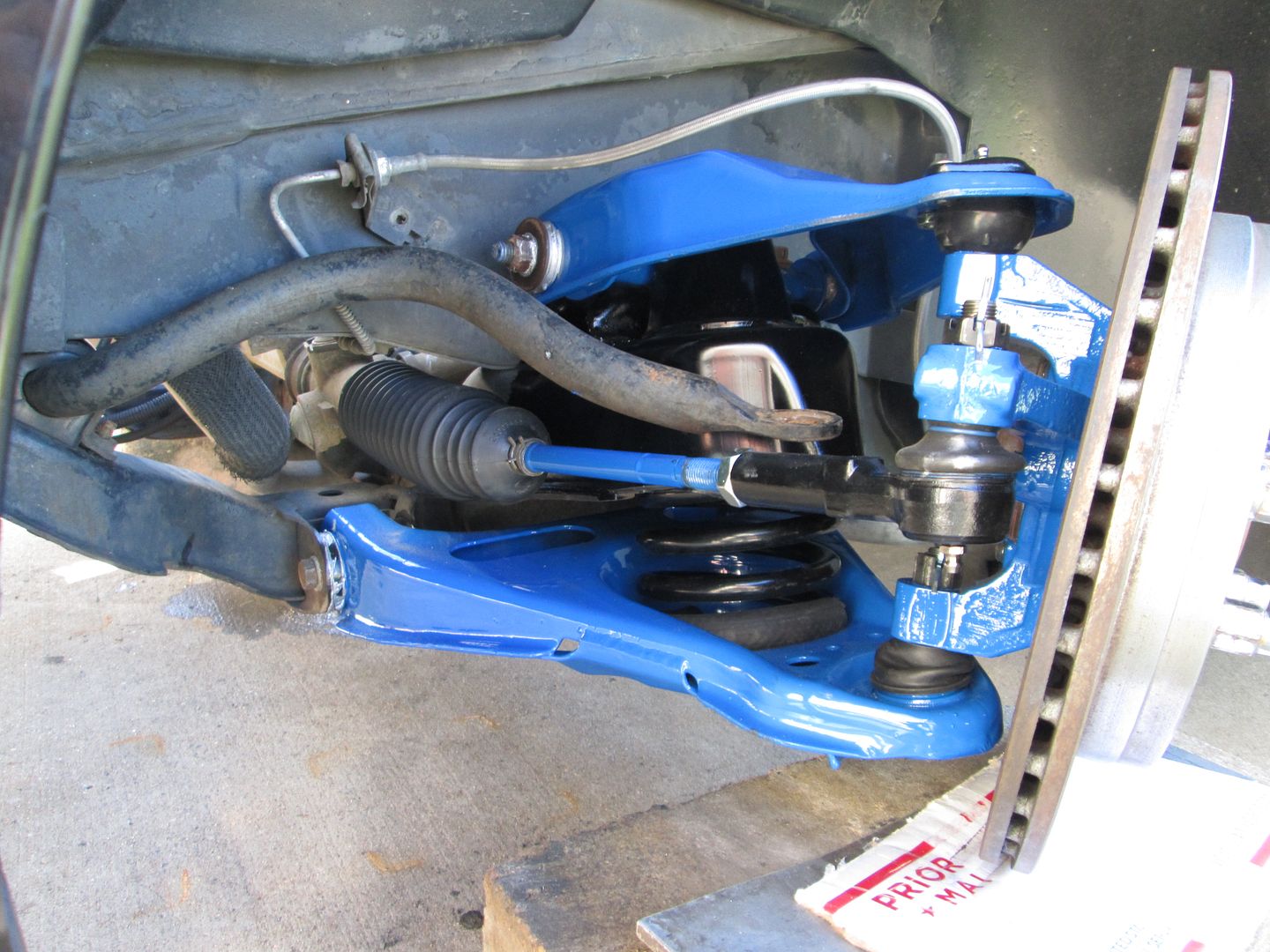
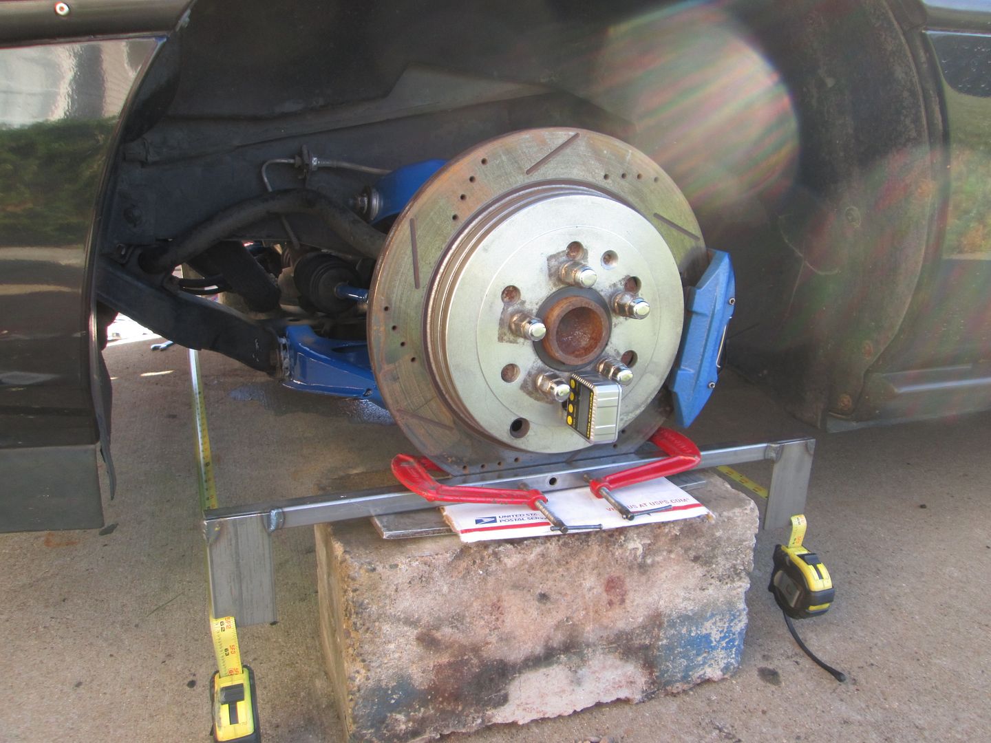
DIY alignment. Camber is within .1 degree side to side (.5 neg) and .1 degree caster side to side - reading was 10.5, but the front the car is raised up a few degrees. It is the maximum amount available. Toe is 1/32 toe in at the front. On Monday I will install the shocks, end links and bump stops, and take it for a shake down run.
If you have an 88 Fiero and don't have the special tool (Kent Moore J-36419) that makes dialing in precise caster/camber a breeze, you need to get it. The adjusters bolt to the end of the cross shaft and push against the frame rail to make small/precise movements to the cross shaft with the suspension loaded and at ride height. The kit contains 2 adjusters, but it would be nice to have another set. I had to adjust both sides to the max to find which one was the true limit, then bring the other back to match the other side.
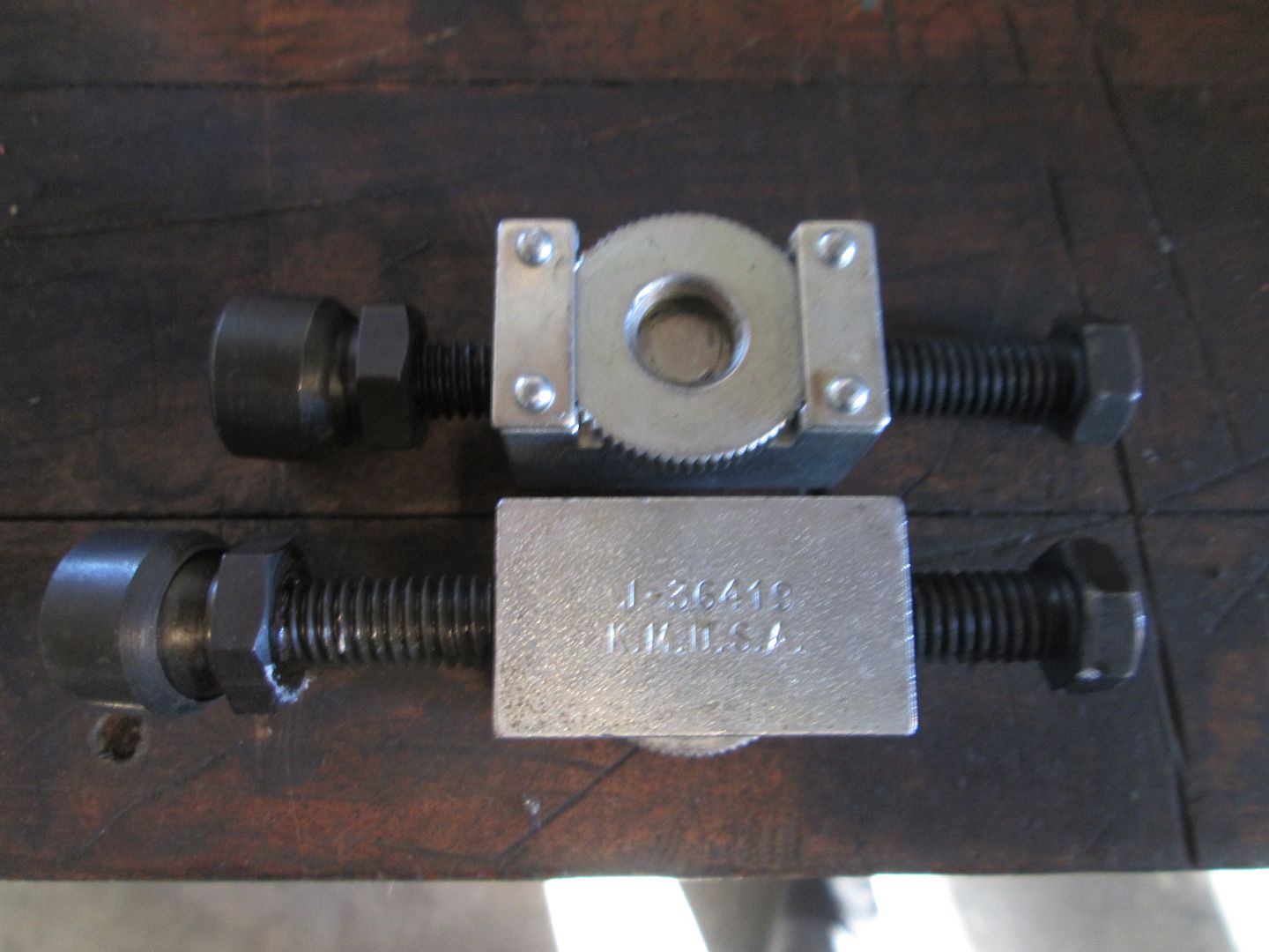 [This message has been edited by fieroguru (edited 09-14-2014).]
|
|
|
|
fieroguru
|
SEP 15, 07:37 PM
|
|
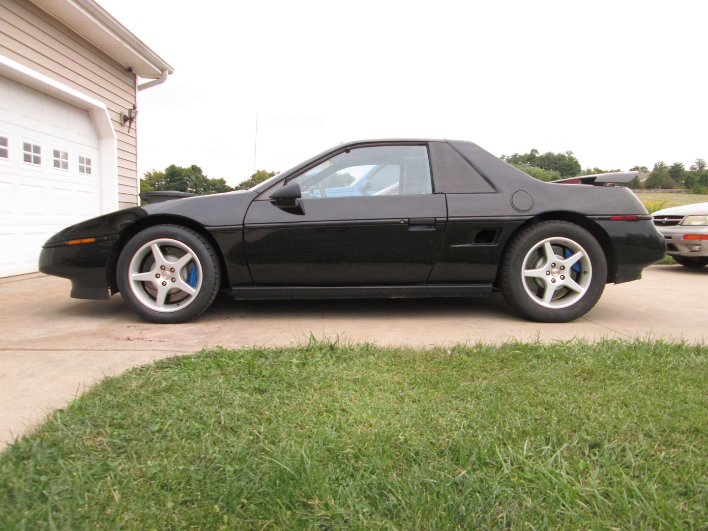
All back together! Took it for a shake down run... and remembered how much I like driving this car!
|
|
|
|
fierogtlt1
|
SEP 15, 08:33 PM
|
|
The Fiero looks awesome Dave  ........What was the color blue you used on the suspension? ........What was the color blue you used on the suspension?
|
|
|
|