
 
     |
| Blooze Own: An F355 Six Speed N* Build Thread (Page 10/126) |

|
Will
|
MAY 13, 01:02 PM
|
|
Large bolted interfaces should be tightened down from the center outward. Thus my suggestion regarding the main bolts.
Did you check ebay for a used Time Sert kit? I will agree that the kit itself is expensive. I did my main bolt holes on a mill and thus only needed the insert installation mandrel... which was something like $150. Absurd.
A 3" steel bolt will expand with the coefficient of thermal expansion of steel, the same as a 6" bolt. There are many reasons to use longer bolts.
|
|
|
|
Bloozberry
|
MAY 14, 08:07 PM
|
|
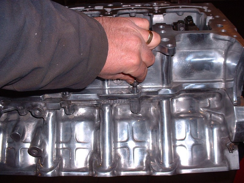
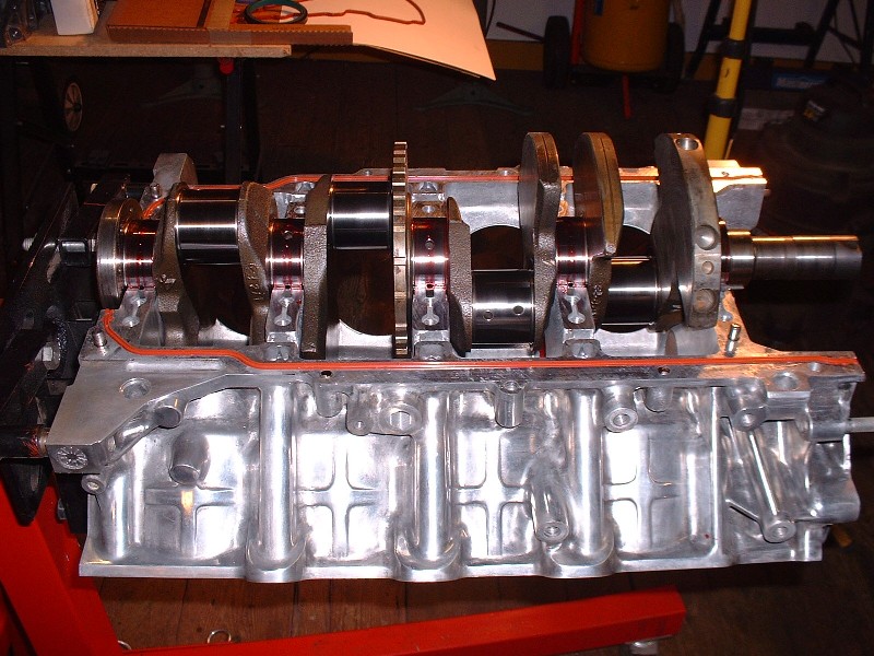
The perimeter bolts I mentioned above are a series of smaller 8mm diameter bolts that secure the lower case-half to the upper case-half next to the seals. Here’s a picture of where the are.
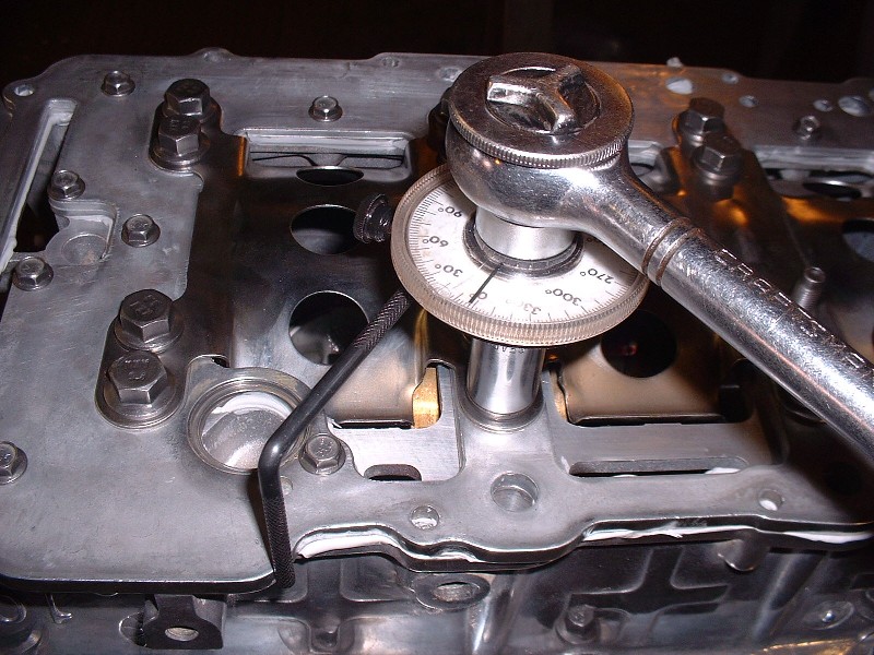
Before the perimeter bolts are tightened, the main crank bearing bolts have to be torqued to spec. The instructions call for a nominal 18 lbft to be applied initially in a particular sequence, then followed-up by turning each bolt an additional 65 degrees. To do this accurately you need an angle gauge on your ratchet wrench. For those who’ve never used one, they’re quite simple… they just attach between the wrench and the socket. There’s a little adjustable arm that sticks out to one side that you must butt up against a steady surface like the side of the block, then you zero the gauge to zero by spinning the face up with wherever the needle is. The last thing you do is turn the wrench, which spins the needle until you reach the desired number of degrees.. The little arm keeps the dial face from spinning along with the needle. It’s really quite simple actually. Lastly, the perimeter bolts get torqued to 89 lb-in.
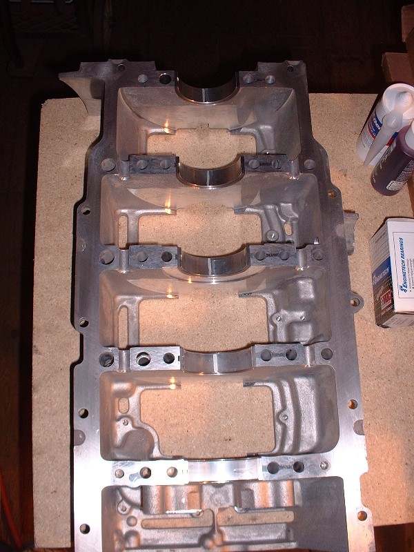
Once again, this is all just to check the main bearing clearances with the Plastigauge, so it’s all got to come apart after waiting about two minutes for it to take a final “set”. The Plastigauge gets squeezed between the bearing surface and the crank journal leaving a line of varying width depending on how tight the clearances are. Here’s what the lines looked like on the lower case half bearing shells.
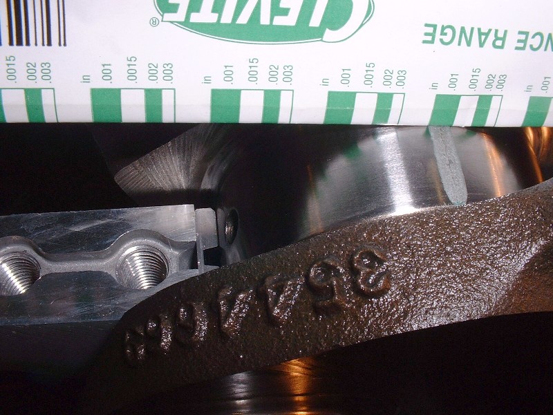
I took my measurements from the marks left on the crank journal. There’s a little scale on the packaging for the Plastigauge that allows you to measure the clearance in accordance with the width of the squished gauge. The spec calls for 0.0006” – 0.020” (yes… that’s six ten-thousandths) whereas mine measured from 0.0010” to 0.0015” so I was happy.
Once you’re done, you can’t forget to clean the Plastigauge off of the journals and the bearings. I find WD40 on a soft cloth does a good job of dissolving it since it gets stuck on there pretty good. You don’t want to use a fingernail on the bearing surface, that’s for sure. Next up is the final crank installation so a good healthy dose of assembly lube on the bearing surfaces is in order… I’ve used the Clevite and the Permatex assembly lube with equal success… this stuff would make a Vampire think about going for a tall cool one.

A final cleaning of the crank journals and Voila!… the crank finds it’s permanent home. A quick spin to lube up the journals all the way 'round and I was ready for the crank end-play measurement.
Crank end-play or float is the amount of fore and aft movement of the crank in the block along the axis of the crank. On a manual transmission it's especially important since everytime you press in on the clutch, it shifts the crankshaft forward along it's axis with a fair bit of pressure. Too much movement and you begin to throw the connecting rods off of their intended plane of movement. The #3 main bearing with the thrust surfaces (shown earlier) is what determines the amount of crank end play.
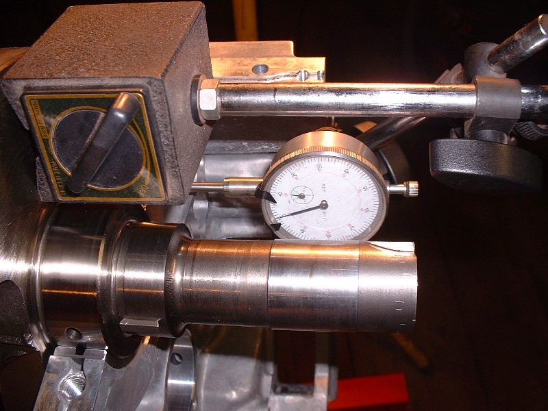
The way I measured this was by sticking a magnetic dial gauge to one of the crank’s counterweights, with the gauge plunger on the stationary bearing web. Then I pushed the crank as far backwards as possible with a small pry bar, zeroed the gauge, then pushed the crank as far forward as it would go and took the measurement. The spec calls for between 0.002” to 0.019” and mine was 0.008”.
With everything in order and within specs, the lower case half was re-installed, along with the oil manifold plate, windage tray, main bearing bolts and perimeter bolts for what was supposed to be the last time… ahhh… ignorance is bliss.
|
|
|
|
IXSLR8
|
MAY 14, 09:18 PM
|
|
Not sure how many of you N* owners frequent the CadillacForums.com site.
Here's an interesting thread on head gasket failures, GM timeserting and the use of other inserts such as Norms. I'm not making a particular statement but rather showing a link where you can find more information on inserts, head gasket failure and related info from a fix perspective:
http://www.cadillacforums.c...ket-failure-fix.html
|
|
|
|
dratts
|
MAY 14, 11:14 PM
|
|
|
With no practical experience I can only theorize. I suspect that norms are better than serts. I would think that even better would be studs. Especially if removing the heads a few times. Can the rwd head gaskets be installed on a fwd?
|
|
|
|
Will
|
MAY 15, 02:14 PM
|
|
| quote | Originally posted by Bloozberry:
Before the perimeter bolts are tightened, the main crank bearing bolts have to be torqued to spec. The instructions call for a nominal 18 lbft to be applied initially in a particular sequence, then followed-up by turning each bolt an additional 65 degrees. To do this accurately you need an angle gauge on your ratchet wrench. For those who’ve never used one, they’re quite simple… they just attach between the wrench and the socket. There’s a little adjustable arm that sticks out to one side that you must butt up against a steady surface like the side of the block, then you zero the gauge to zero by spinning the face up with wherever the needle is. The last thing you do is turn the wrench, which spins the needle until you reach the desired number of degrees.. The little arm keeps the dial face from spinning along with the needle. It’s really quite simple actually. Lastly, the perimeter bolts get torqued to 89 lb-in.
|
|
Be sure to go back and RE-torque the sequence to 18 ftlbs BEFORE applying the 65 degrees. The first bolts in the sequence WILL relax as you tighten down the bolts around them.
|
|
|
|
Bloozberry
|
MAY 15, 04:30 PM
|
|
I forgot to mention that Will... thanks!  This is very true whenever torquing anything with a torque wrench.. always go back and and retorque all of the fasteners a second time to pick up the slack on the first fasteners created by the last ones. Even though this isn't mentioned in the assembly manual, it's common sense. In my case, I think I put another 30* or so on the first few main bolts before the torque wrench "clicked" at 18 lbft the second time around. If I hadn't rechecked, then clearly the first few main bolts would have been under torqued by 30* when all was said and done. This is very true whenever torquing anything with a torque wrench.. always go back and and retorque all of the fasteners a second time to pick up the slack on the first fasteners created by the last ones. Even though this isn't mentioned in the assembly manual, it's common sense. In my case, I think I put another 30* or so on the first few main bolts before the torque wrench "clicked" at 18 lbft the second time around. If I hadn't rechecked, then clearly the first few main bolts would have been under torqued by 30* when all was said and done.
|
|
|
|
Bloozberry
|
MAY 17, 09:35 PM
|
|
With the lower case-half installed, I could finally move on to installing the sparkly new pistons. Or could I? Within minutes of having torqued the main bearing bolts for the second time, it dawned on me that there was no way I was going to be able to install the connecting rod caps and bolts with the lower half of the engine installed. There just isn’t any room… especially with that windage tray in the way. Rats! I got ahead of myself.
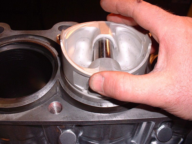
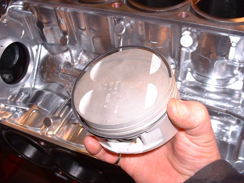
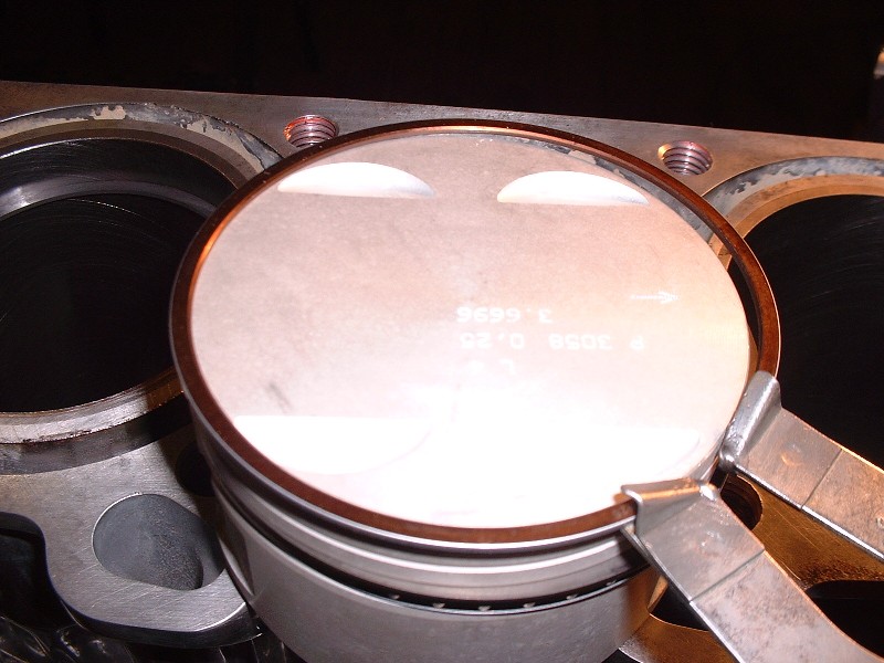
Before removing the lower end again, I decided I’d turn the engine upright (something you can’t do with the lower case-half off without the crank falling out!) and measure up my compression ring gaps. If you’ve never rebuilt an engine before, when you measure the ring end gaps you have to ensure they’re level in the cylinder or they’ll throw off the measurement. The best way to do this is to slip a ring into the cylinder and push it down an inch or two with an upside down piston. It’s easy to make sure the piston is level since there are all kinds of ring lands to line up with the deck surface.
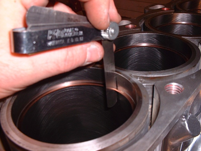
Once the ring is in level, pull out the piston and measure the ring gap with a feeler gauge. You have to do this with all 32 rings (1 top ring, 1 middle ring, and two oil scraper rings per cylinder) and make sure you dedicate each ring to the cylinder that it was measured in. Not all cylinders are exactly the same diameter, and not all rings are exactly the same size, so to file as few ring gaps as possible, I measure all the rings starting with the lower scraper rings first, then swap around tightest and loosest rings until I get the end gaps to match as close as possible between all of them. The oil scraper ring end gaps on a Northstar are allowed to be 0.010” to 0.030”. Once I was finished moving them around for the best fit, mine were from 0.010” to 0.013”… not bad at all. Then I move on and do the same for the two compression rings. By mixing them up I was able to avoid any ring gap filing and therefore maintained the nice, even, factory square edges.
Next up is to install them, starting with the lower oil scraper ring, the spacer, upper oil scraper, lower compression, and then upper compression ring. You have to install them in this order because the rings get installed from the topside of the piston and you can’t stretch a lower ring over top of an upper ring if it were installed before the lower ring… it just doesn’t work. The oil scraper rings are easily installed with your fingers…
…but the two compression rings are best installed using a ring expander.
I bought a master engine rebuild kit that basically comes with everything you need to rebuild an engine. It’s the cheapest possible way because to buy the parts individually you’d pay easily 1.5 to 2 times as much for the same parts. I ended up buying my kit from a company called EngineTech because they were one of the two companies that offered 0.25mm oversized pistons that I could find. There were choices between hypereutectic and coated pistons from other companies, but as far as my budget was concerned, I thought it best to spend the money on other things.
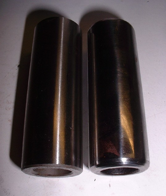
I was happy with the quality of the parts from EngineTech except for the piston wrist pins. They weren’t consistently the same length, nor were they consistently chamfered at both ends. Here’s an example of two pins from the same kit. To be honest, I’m not sure I would have noticed except that when I went to install the retaining clips, 5 of the wrist pins were too long. I ended up having to shorten and/or chamfer all 8 pins to one degree or another.
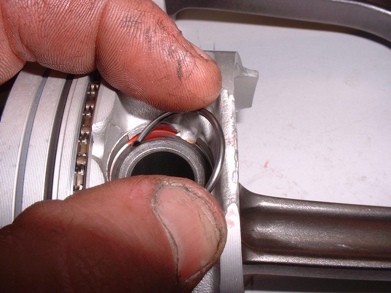
Once that bit of business was taken care of, I was able to assemble the connecting rods to their respective pistons… (note the ugly busted knuckle… the result of losing a fight with rounded bolt on a customer’s car)
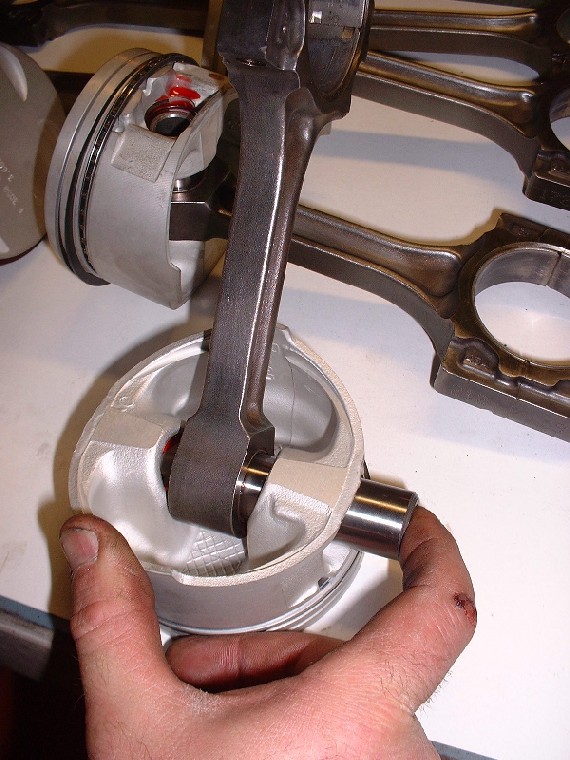
… and install the spring clips to retain the wrist pins… (I know, I have an ugly thumbnail too… from flipping the nail on another customer’s car… ouch!). You can see from this photo why too long or improperly chamfered wrist pins cause a problem. You can get one spring clip in place, but you just can’t seat the second one.
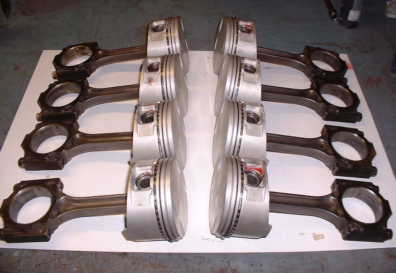
Finally, here’s a couple shots of the completed rods and pistons ready to be installed in the block… well, once the lower case-half was removed again.

 [This message has been edited by Bloozberry (edited 05-18-2010).]
|
|
|
|
Tony Kania
|
MAY 18, 01:14 AM
|
|
A beginner could damn near build his first engine with the information, and pics that you provide in this thread. And a free bump. 
|
|
|
|
bamman
|
MAY 18, 03:20 AM
|
|
|
Do I know you, I have a 4.9 in my 88 fiero and I live in Brooklyn. I would have met you at the Berwick car show.
|
|
|
|
bamman
|
MAY 18, 03:34 AM
|
|
|
No need to reply to the post above from me. We have met. This looks like a great project for you, great workmanship you have. I still think about the go-cart. Someday I will make plans to visit you at the "old farm" when cruising the valley. My fiero is painted black and is a fifty footer. Bye for now.
|
|
|
|