
 
     |
| How To: Install Automatic Headlights in your Fiero! (Page 1/1) |

|
rbell2915
|
JUL 04, 06:19 PM
|
|
This modification is pretty easy, I've done it twice now and will do it a third time for a friend who just picked up a Formula. A member here used to sell kits and no longer does, so here is how you can do it yourself if you'd like to tackle it yourself. This will work in cars with the Gen 2 headlights certainly, potentially with the Gen 1 system as well but I have no way of confirming that.
What you'll need:
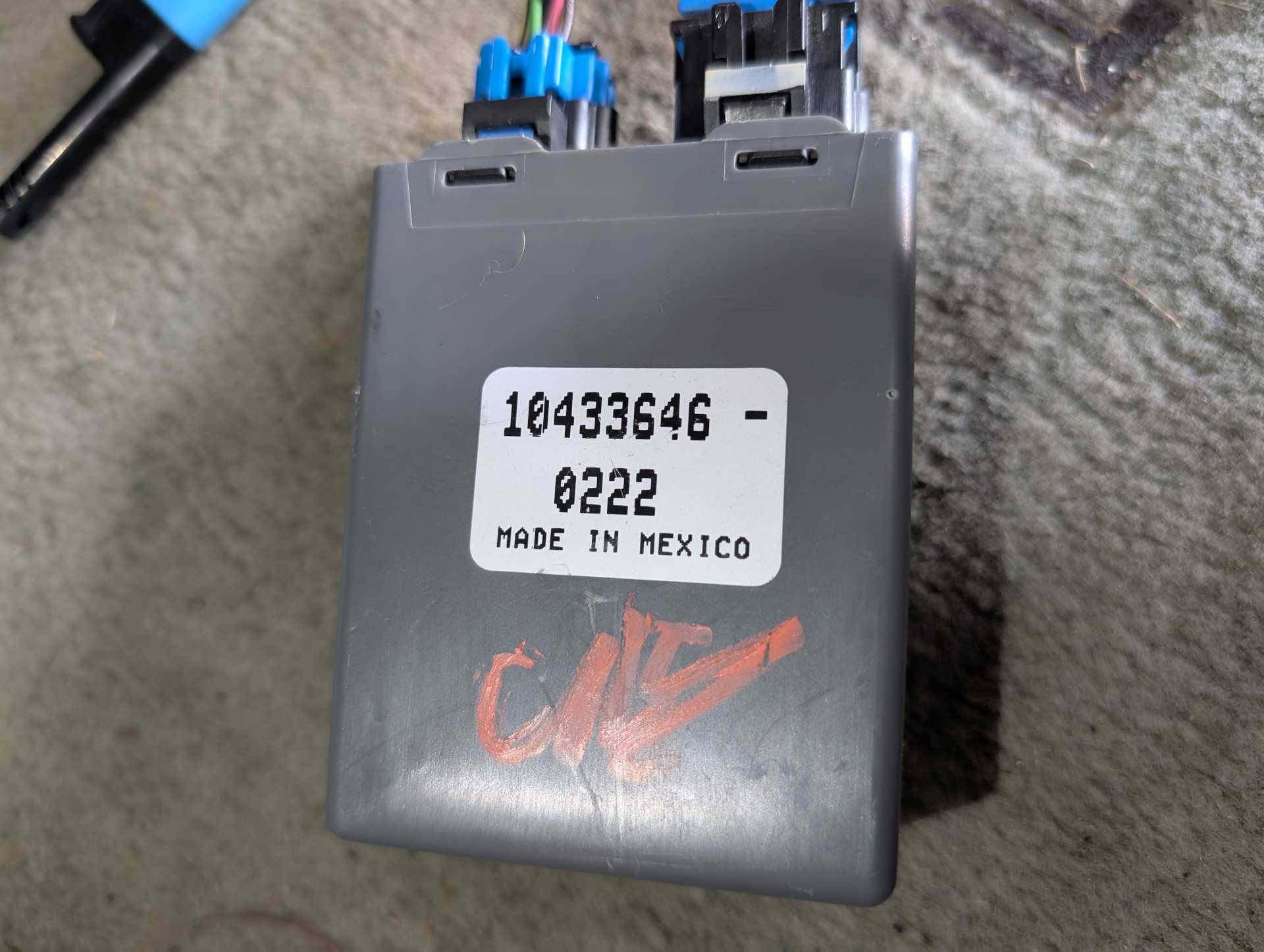
- 1998-2002 Grand Prix Headlight Module, you will find these underneath the driver side dashboard above the left knee, it's a small gray box. Grab that along with the two plugs and wiring.
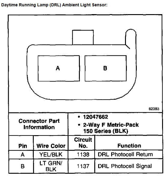
- Sun sensor in the center of the Grand Prix dashboard and the trim piece surrounding the sensor. Make sure you grab the wiring harness plug and a length of wire as well.
- Fiero headlight switch, wiring plug, and pigtail. We will use this to create a plug n play connector so we don't have to destroy the car's wiring.
- Add a Circuit, the module needs a 10a fuse for protection.
- Ring terminal for the ground.
- Soldering iron, solder, wire crimpers, variety of butt connectors and shrink wrap, etc. whatever your preferred choice of wiring modifications is. Some wires are thick and it may be difficult to solder four of them together so I opted to crimp them, and I opted to solder other wires.
- Electrical tape and a glue for potting.
- Tools to take the headlight switch out, rear cluster cover, and the lower dash cover off.
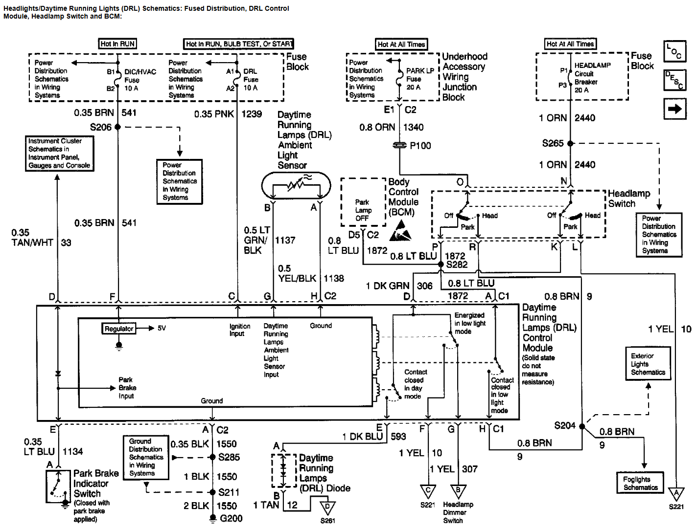
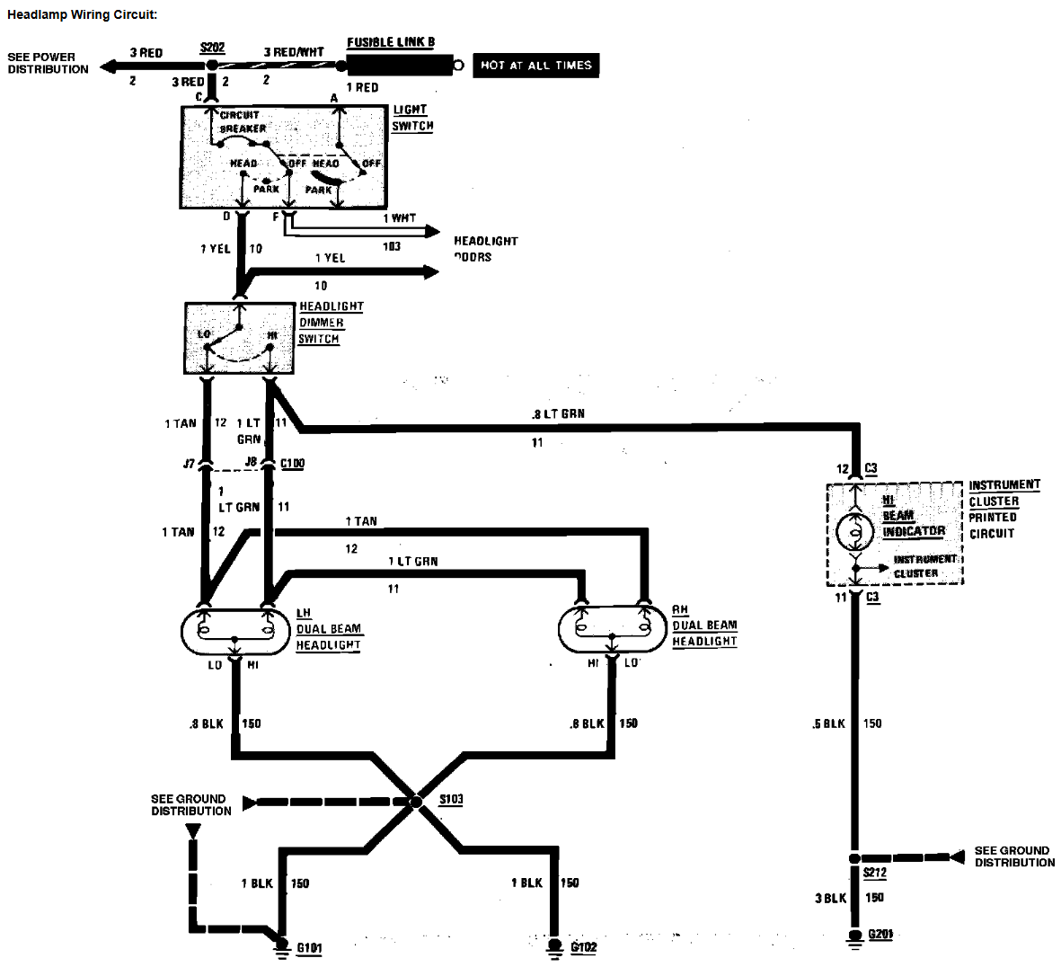
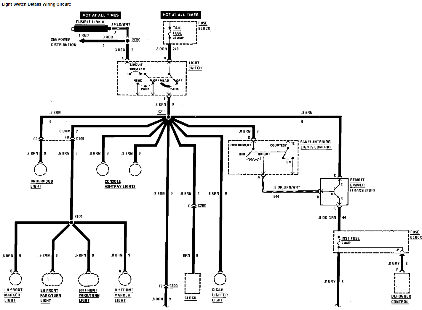
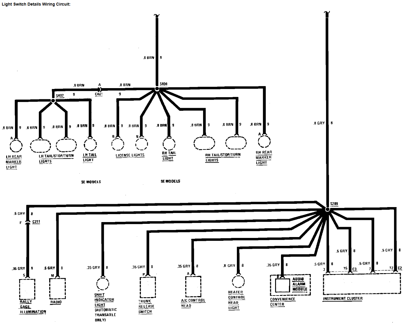
Wiring diagrams and connector views:
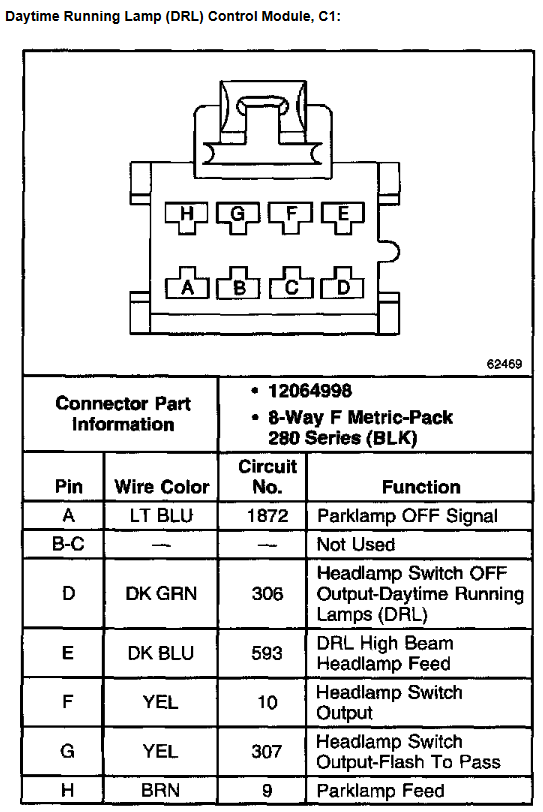
- Automatic Headlight Module
- Fiero
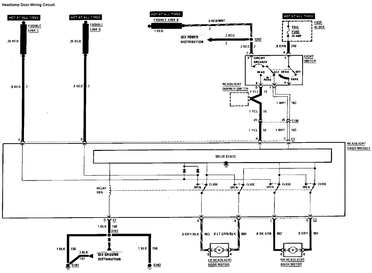
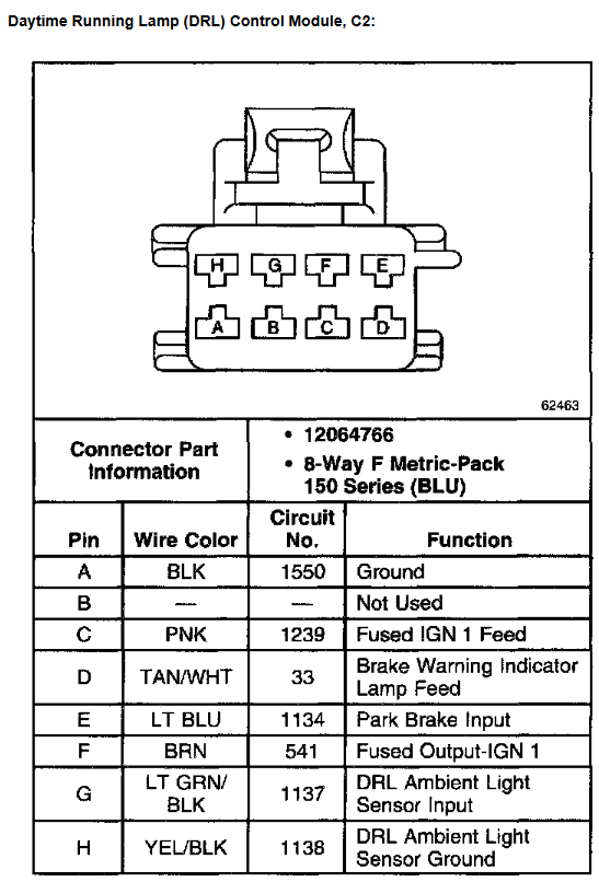
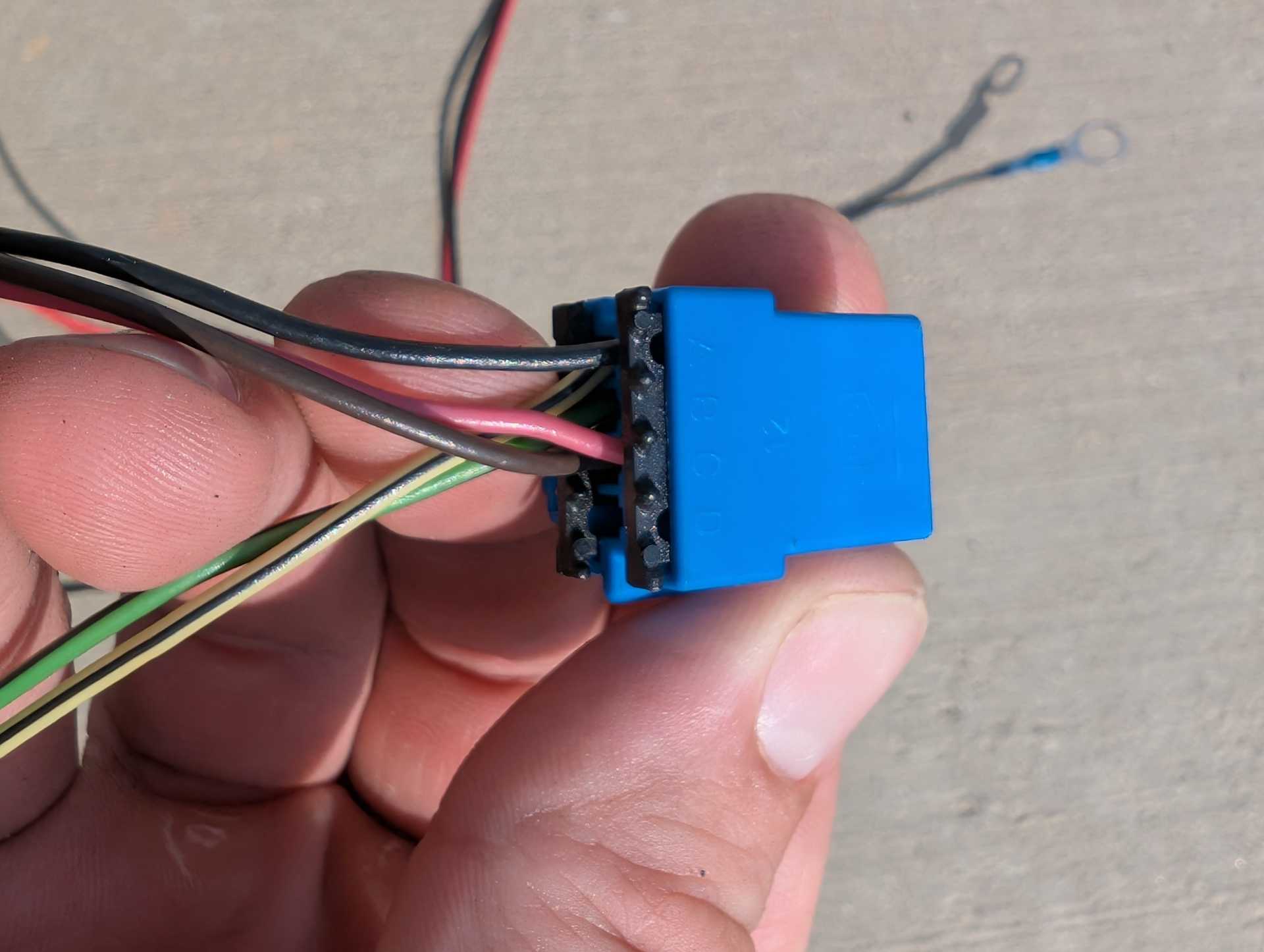
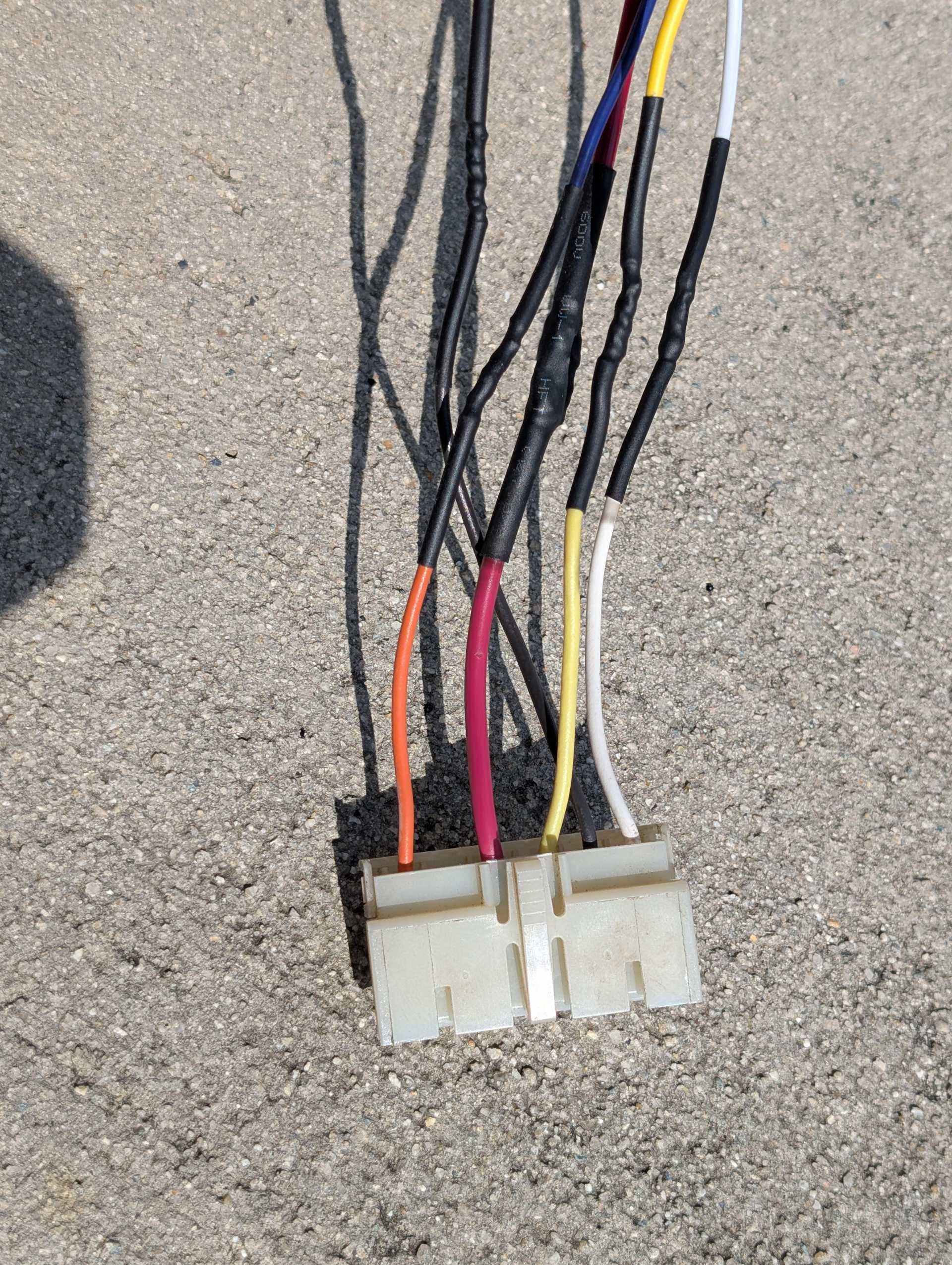
- Module C2 Connector:
These are the only wires that are needed on the connector, you can remove everything else.
On your sun sensor, solder a red wire on grn/blk and a black wire on yel/blk and then solder those to the corresponding wires on the module's C2 connector which are pins G and H respectively.
Pink C and Brown F can be connected together, extend the wire a bit and you will put the add a circuit onto that end. I opted to put it in the gauges fuse on the fuse box as it's ignition powered and also 10a.
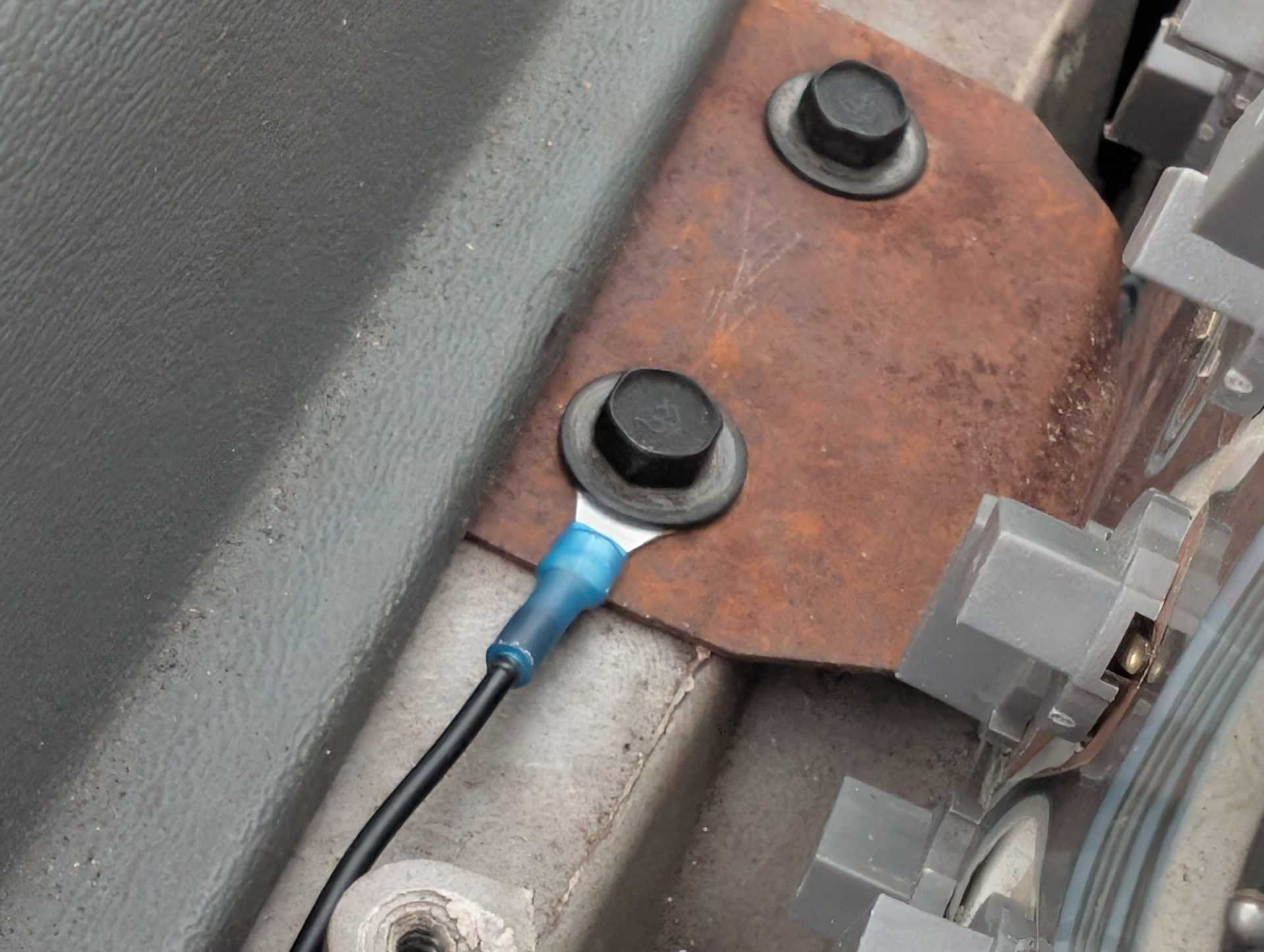
Last wire is the ground which is Black A, extend this wire and put a ring terminal on the end. I like to use the left 10mm bolt spot on the instrument cluster mount for the ground here.
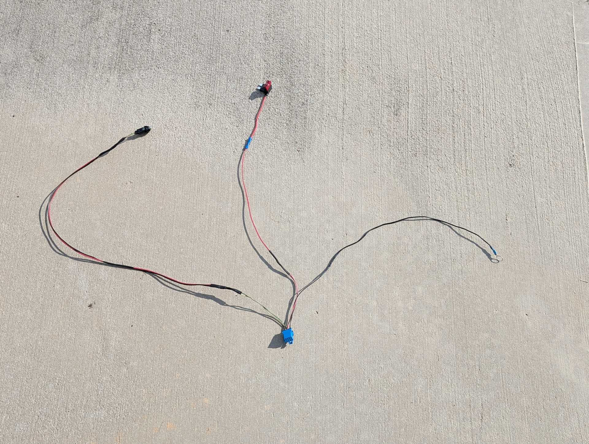
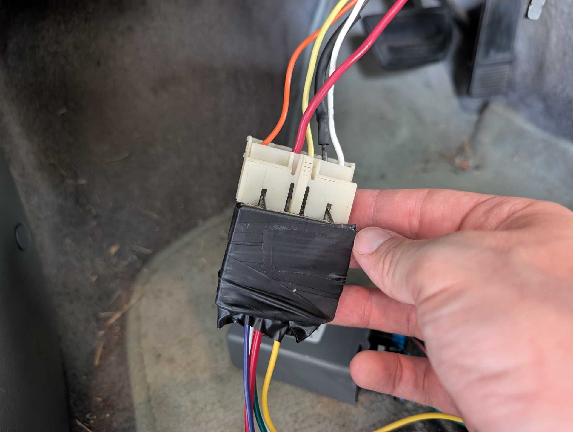
Now we're halfway done! You should have something that looks like this:
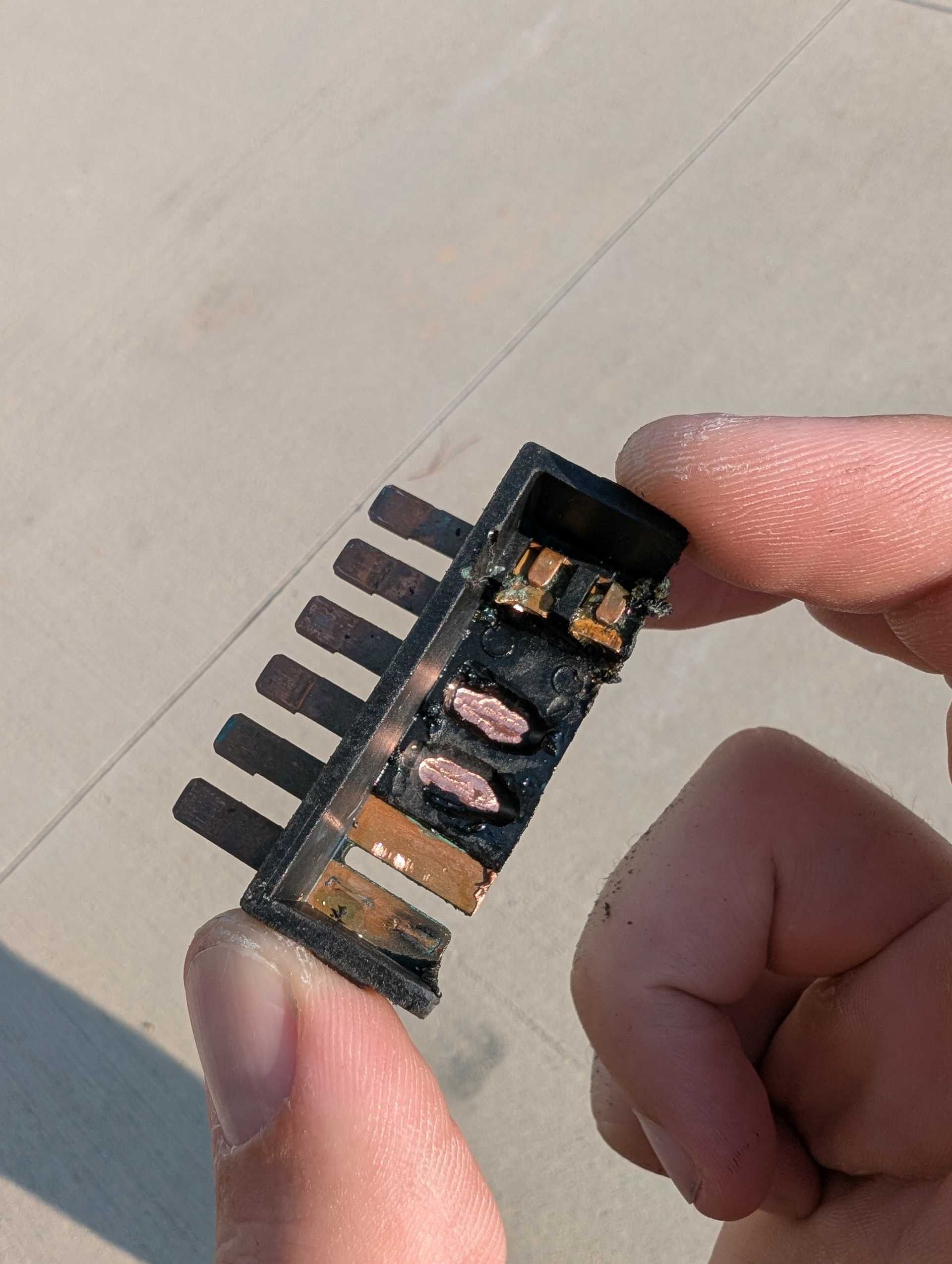
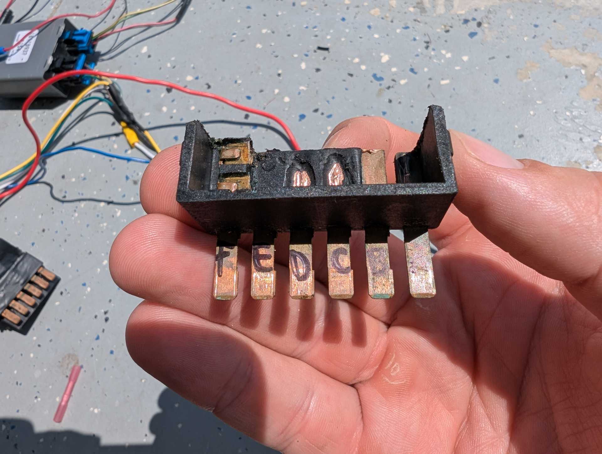
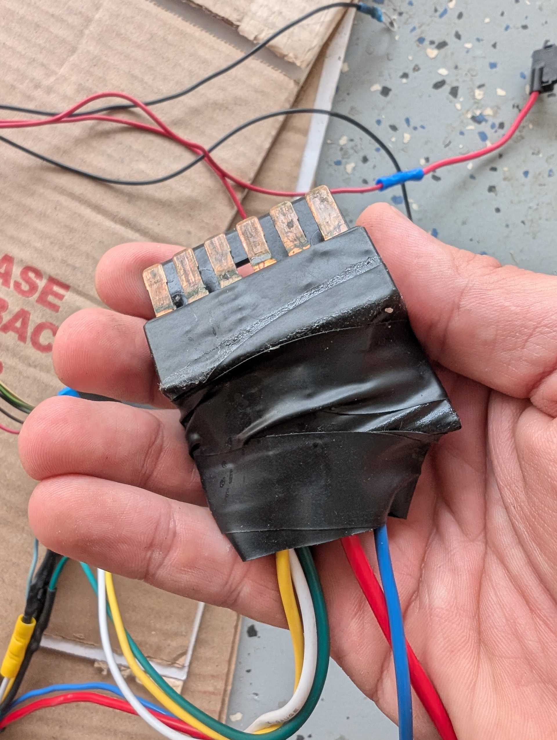
You are going to want to take your junkyard Fiero switch and pop the body apart and cut it down to look like this and grind the plastic away to get to the terminals to solder wires on top. Make sure that you keep the black cover that the white plug interfaces with. You don't need the switch controls. Throw those away.
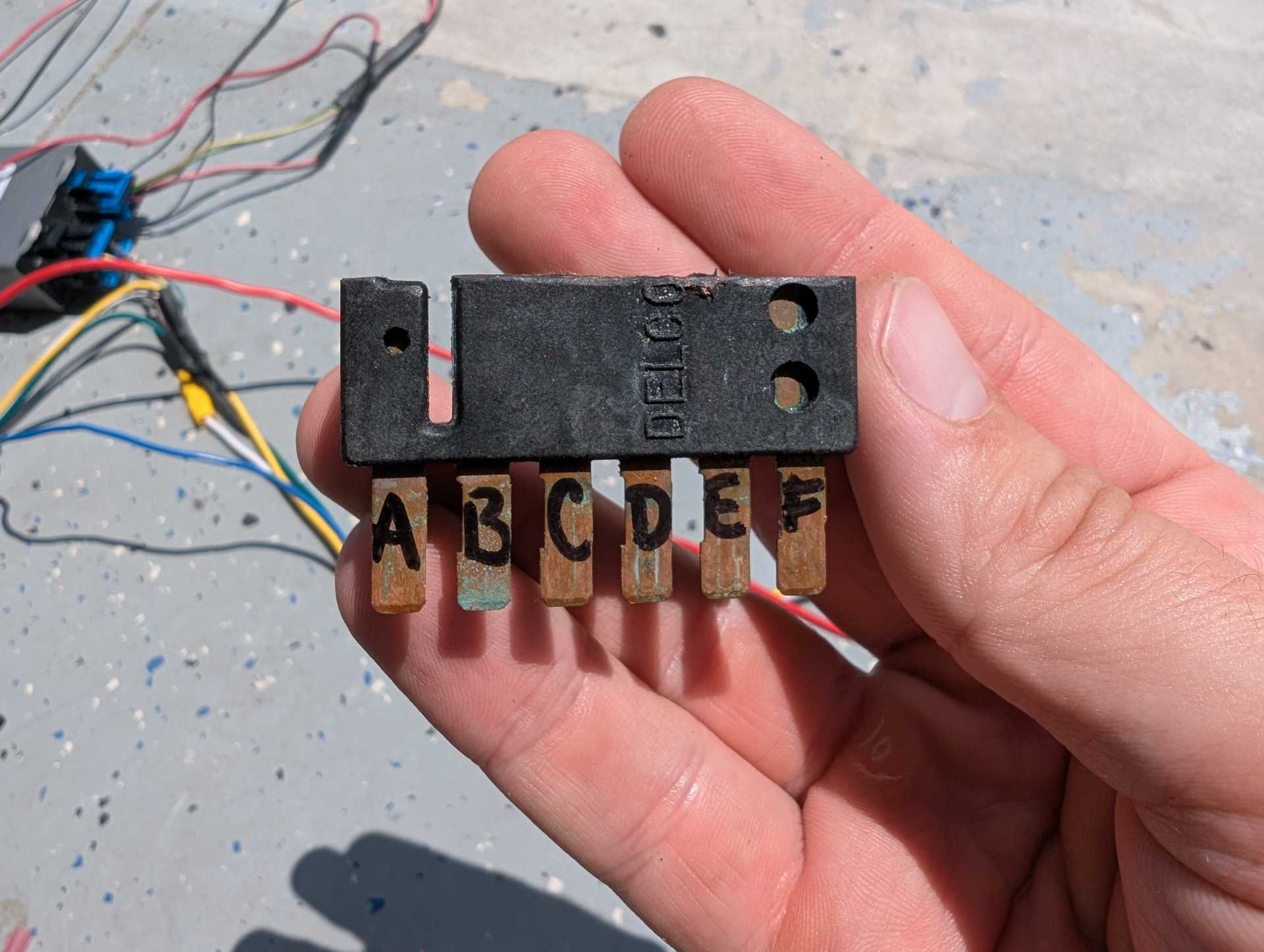
Mark the pins like this with a sharpie, these will correspond with the white connector's pins so you can easily make your harness.
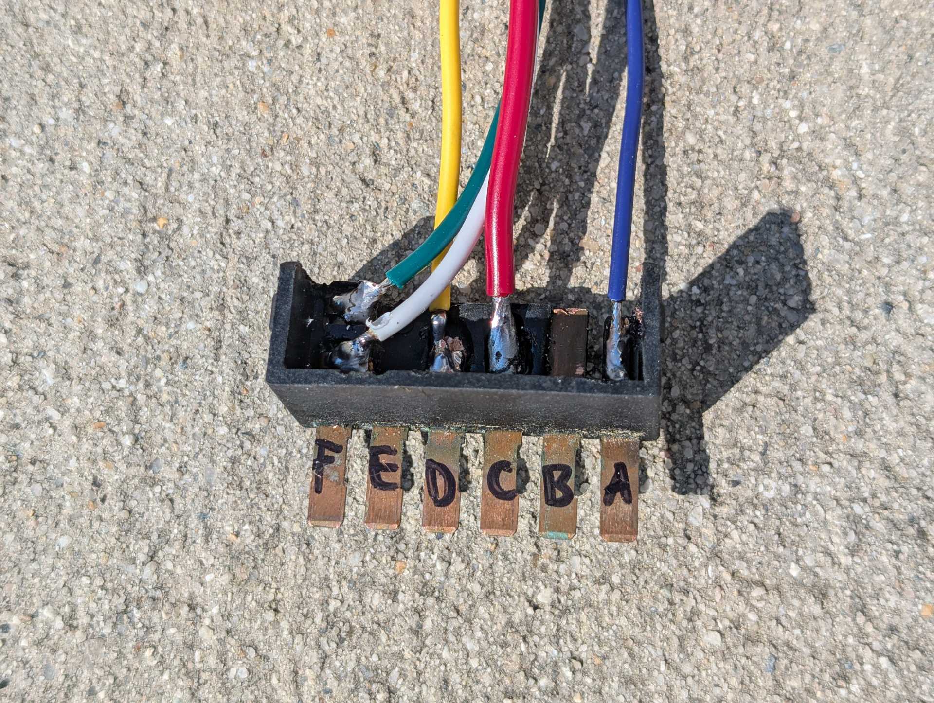
Solder wires on like this, I didn't have access to a brown wire so I used green, and a blue wire instead of orange. If you have the proper colors, use those.
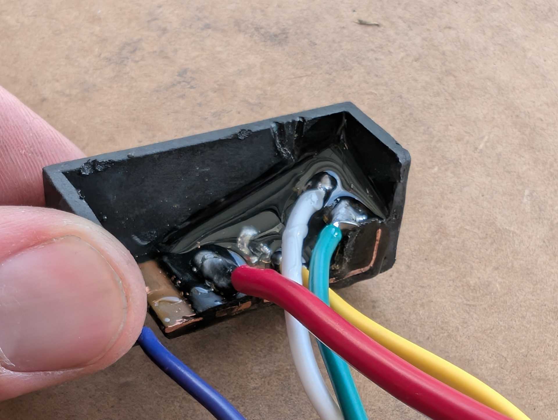
I like to use glue to pot the wires and to ensure that nothing will short out just in case...
Now, you are going to connect those wires that you soldered onto your modified plug to the white plug you got from the junkyard. This will make a plug n play harness.
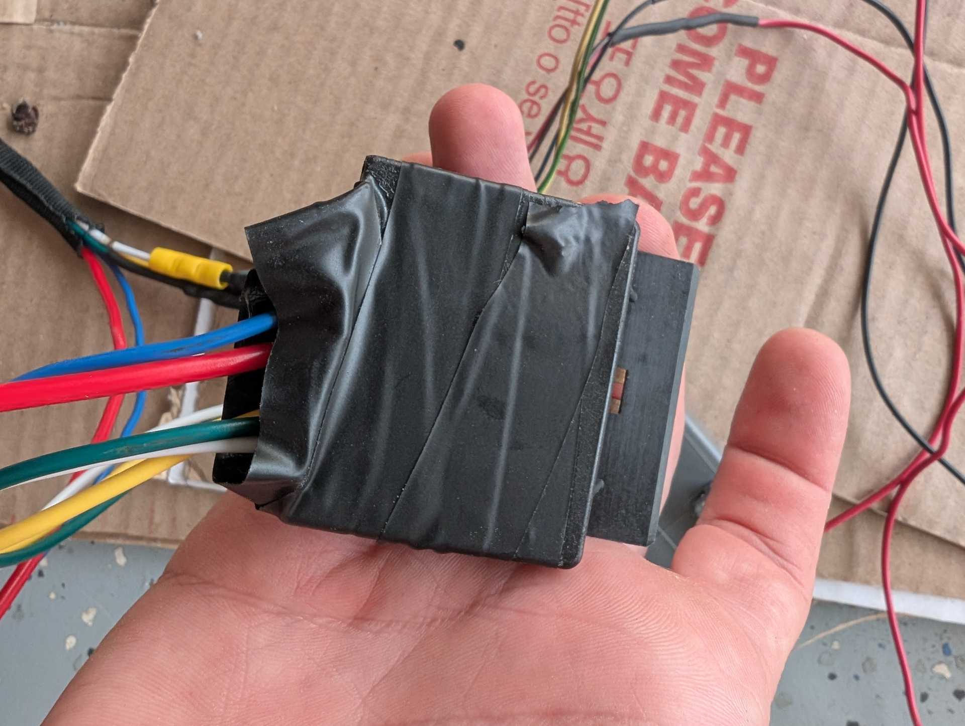
On your black connector, put the black cover back on and tape it shut for insulation and you're done.
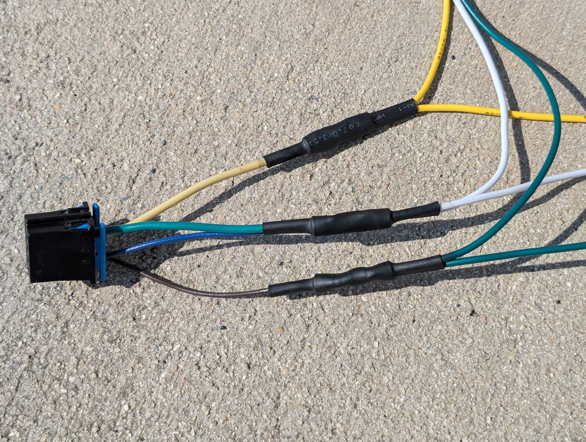
- Module C1 Connector
Now, all we need to do is to splice the headlight module into this harness, and we are finished. We are now going to work on C1 of the module.
If you have stock headlights, AKA no DRLs or fog lights, you'll only need to use four wires on this connector and splice this connector into your plug in play harness like this. I do not have DRLs or fog lights, but I believe that you would hook the E wire up to those. Or you can choose not to. Regardless, the diagrams are up above for your reference to play around with as you choose. I don't have those, so I took wire E out of the connector.
Brown H will go into the brown wire on the car, which is my green on the harness.
Yellow F will go into the yellow wire in the harness.
Blue A (on some modules this wire may be an orange! That was the case on my second module, but I switched it out for a blue wire I had laying around) and Green D will get connected together and spliced into the white wire.
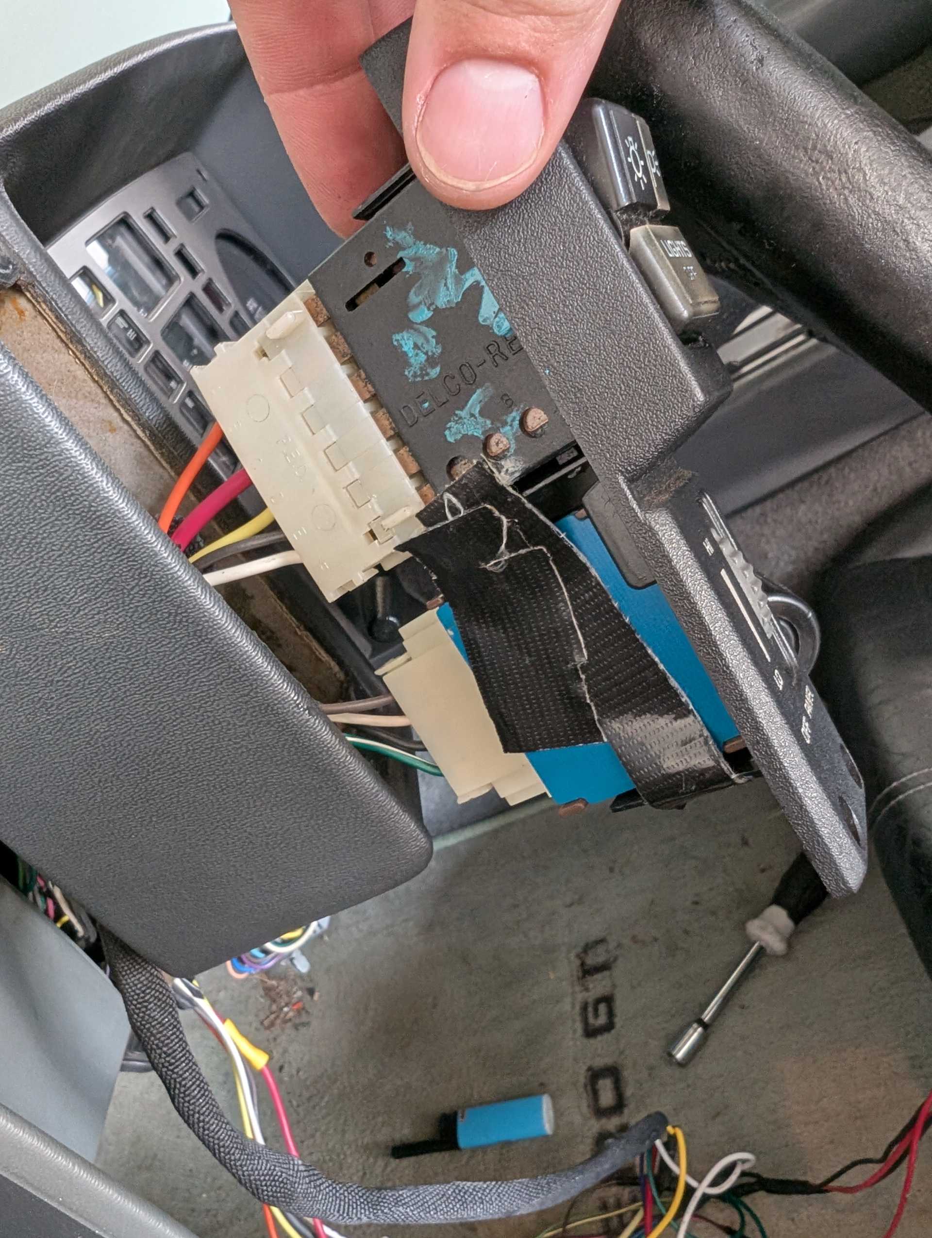
After that, go into your car and disconnect the battery and remove the rear cluster cover and the lower cover and the headlight switch. Plug the module power wire into the gauges on the fuse box, ground it, and plug in the plug n play harness between the car's plug and the headlight's plug.
I need to get around to finding a new switch bezel, this has been broken for too long...
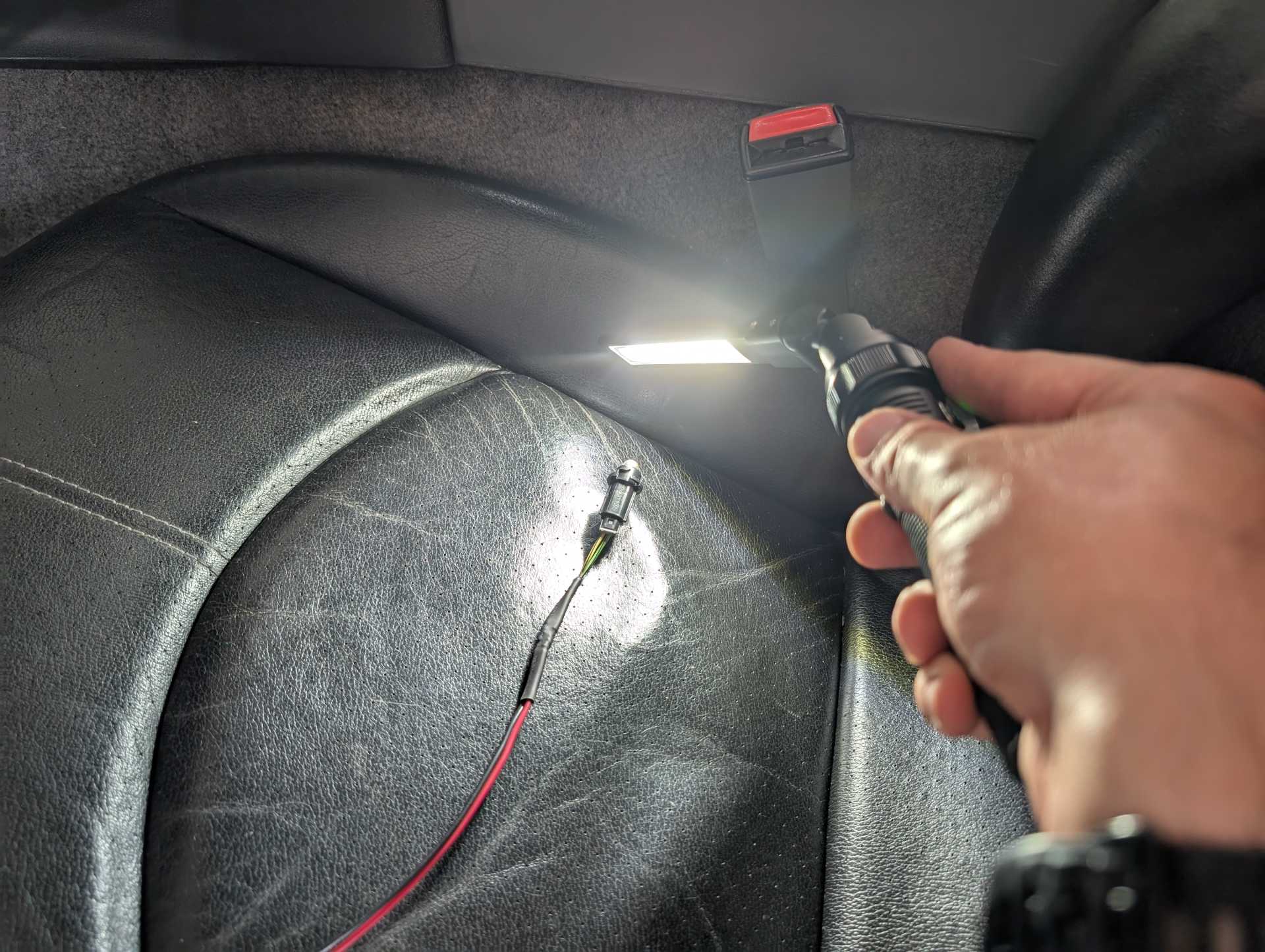
Turn your car on and cover the sensor and it should work and the dash should illuminate, headlights come up and on, and the parking lights come on. Shine a light on the sensor to lower the lights and make sure everything comes off.
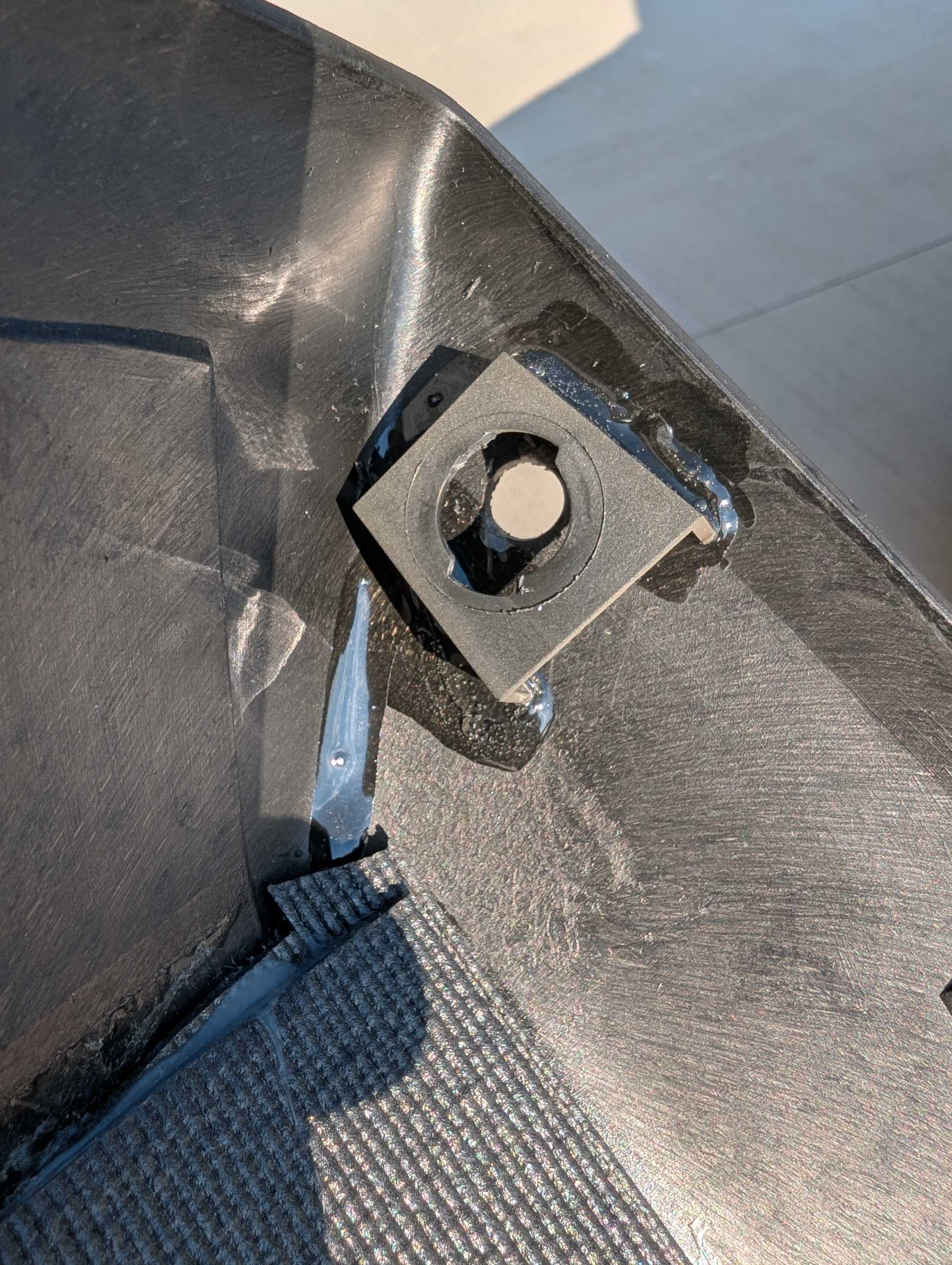
After confirming everything works, take your rear gauge cover and the sun sensor trim and carefully cut the mounting piece off the sensor trim and glue that onto the rear cover, high and to the left side like this and let it cure:
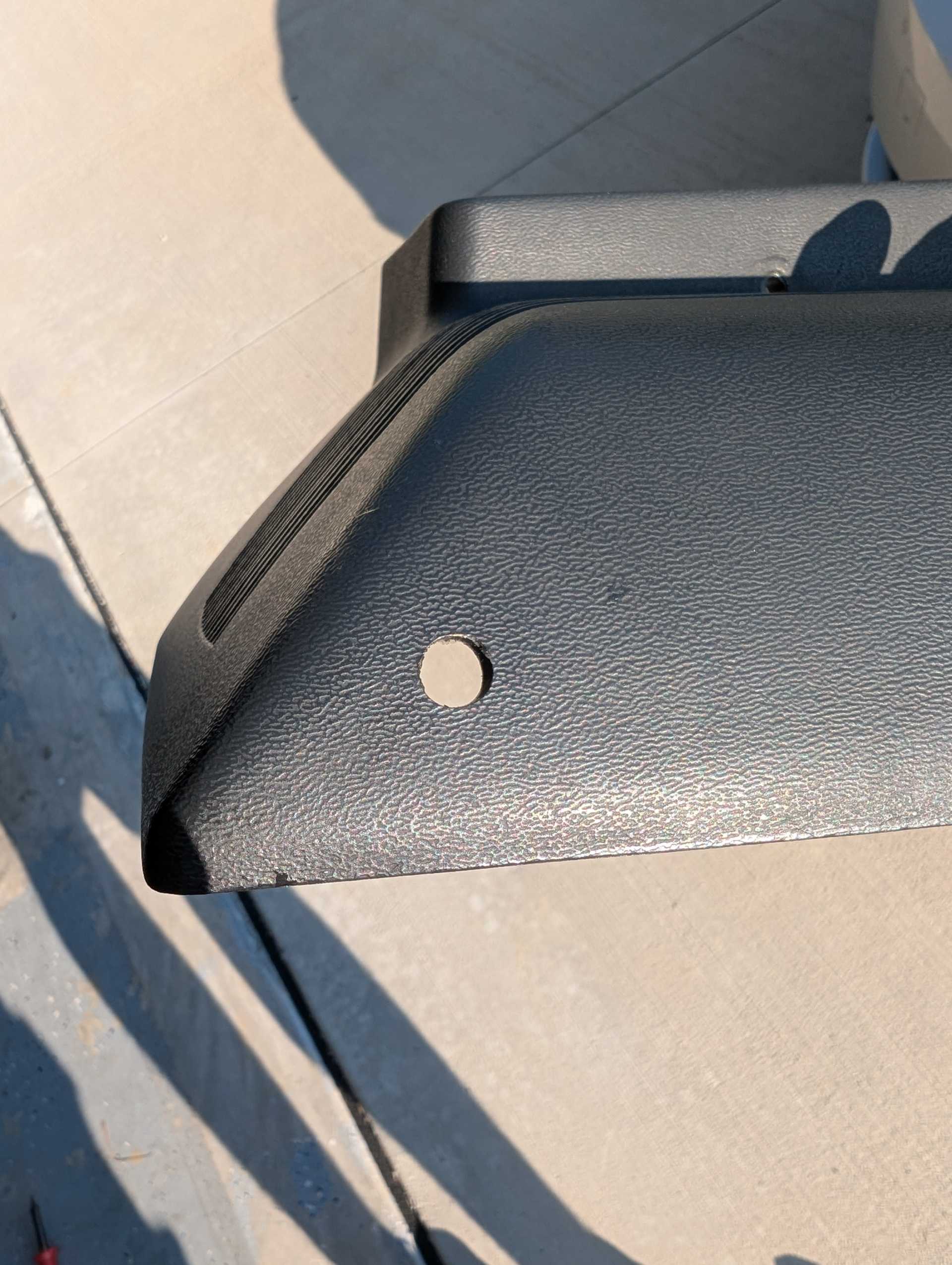
Then use a drill and make a hole for the sensor to see the light:
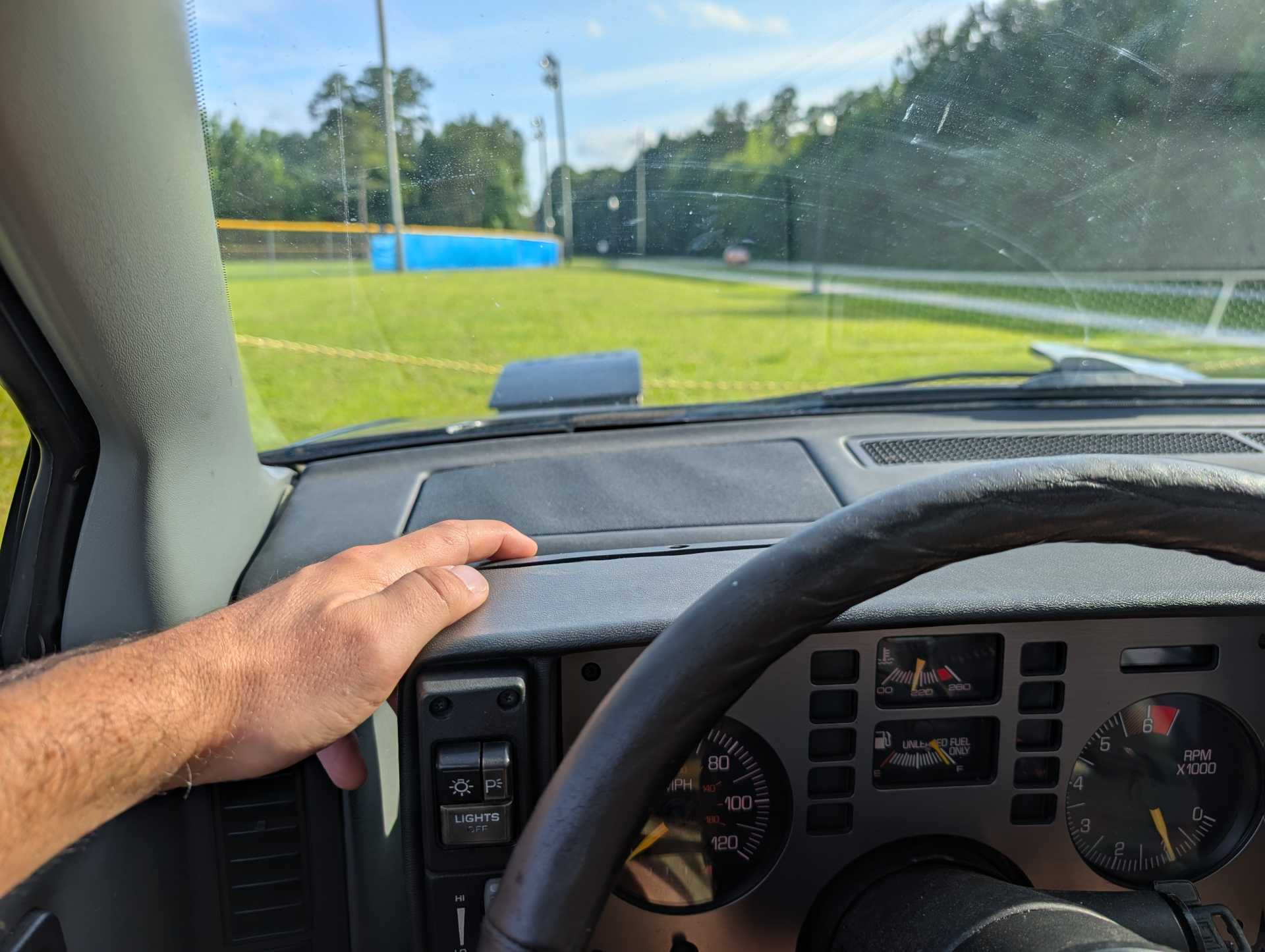
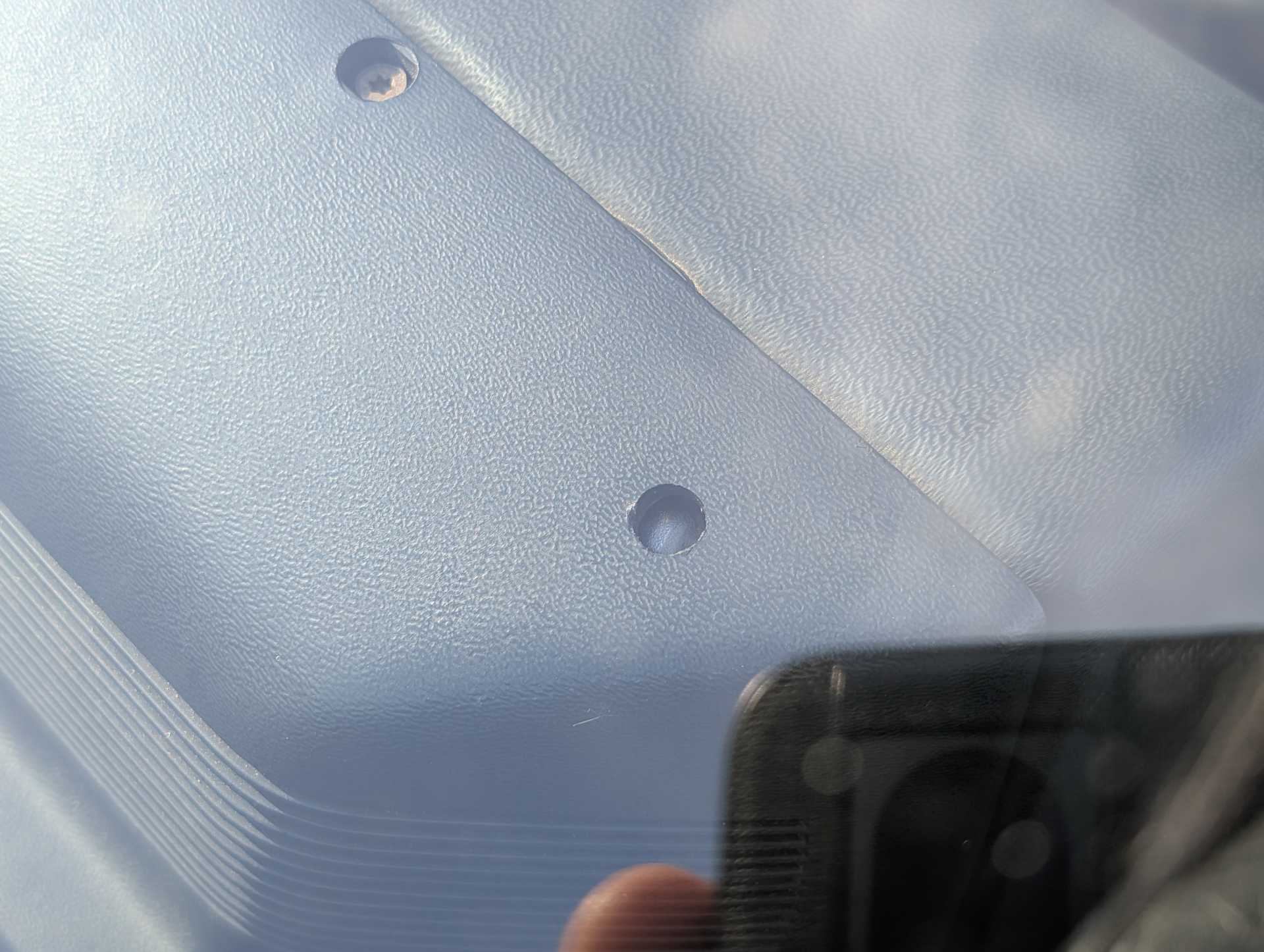
After that, you can put everything back together and hide the module underneath the dash and it'll look like this when you're done.
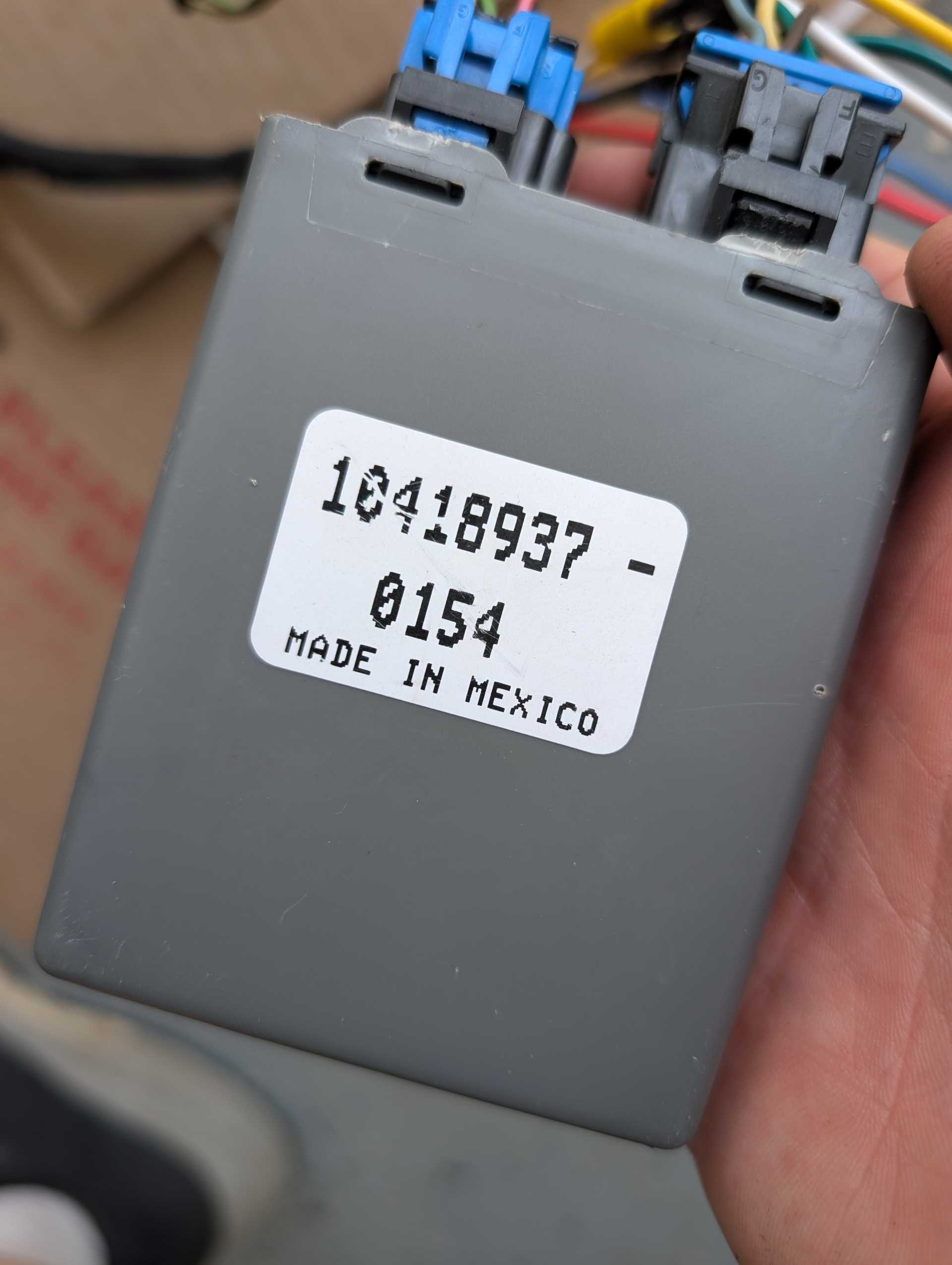
Here are the two modules that I used so you can reference the part numbers, but it'll work for any module.
Hope it works great for you like it did me  [This message has been edited by rbell2915 (edited 07-05-2025).]
|
|

|
RCR
|
JUL 08, 12:34 PM
|
|
Nice write up...thanx... May have to do this before I put my dash back in...
I take it the manual switch still operates the lights.
Bob[This message has been edited by RCR (edited 07-08-2025).]
|
|
|
|
rbell2915
|
JUL 08, 12:42 PM
|
|
| quote | Originally posted by RCR:
Nice write up...thanx... May have to do this before I put my dash back in...
I take it the manual switch still operates the lights.
Bob
|
|
Yes, you can turn the lights on any time you want 
|
|
|
|
reinhart
|
JUL 12, 04:07 PM
|
|
|
Cool idea thanks for the good writeup!
|
|
|
|
rbell2915
|
JUL 12, 06:10 PM
|
|
| quote | Originally posted by reinhart:
Cool idea thanks for the good writeup! |
|
You're welcome, let me know how it goes if you decide to give it a shot!
|
|
|
|
RCR
|
JUL 17, 07:10 AM
|
|
I tried this last weekend. The salvage yard did not have a correct year Grand Prix, so I scoured the yard and came up with a 98 Intrigue. After spending hours going through schematics and mocking it up, don't bother. The Grand Prix is the only model with automatic headlights controlled by the DRL module. If another model has them, it's controlled by the BCM.
Motto of the story, follow the above instructions.
Bob
|
|
|
|
rbell2915
|
JUL 17, 07:22 AM
|
|
| quote | Originally posted by RCR:
I tried this last weekend. The salvage yard did not have a correct year Grand Prix, so I scoured the yard and came up with a 98 Intrigue. After spending hours going through schematics and mocking it up, don't bother. The Grand Prix is the only model with automatic headlights controlled by the DRL module. If another model has them, it's controlled by the BCM.
Motto of the story, follow the above instructions.
Bob |
|
My favorite yard has lots of these Grand Prix. I'll keep an eye out for you. I'll probably be going back there again this weekend or next.
|
|
|
|
RCR
|
JUL 17, 03:52 PM
|
|
| quote | Originally posted by rbell2915:
My favorite yard has lots of these Grand Prix. I'll keep an eye out for you. I'll probably be going back there again this weekend or next. |
|
Thanx, no worries. I've got the yard watch on now to ping me when one shows. May do the entire BCM swap...Never know with this project.
Bob
|
|
|
|