 
     |
| CNC help (Page 1/1) |

|
sspeedstreet
|
APR 16, 02:38 PM
|
|
I'm trying to get some insight from people who do CNC machining. I'm working on headers for my 1992 3.4DOHC engine (in a 1988 GT). For the flanges I'm making individual pieces to blend the "D" port shape over to the correct round diameter. I have the pieces to the correct thickness and the profiles (outer shape, pipe ID and the bolt holes water jet cut. I'm now faced with cutting the blend profile by hand (ugh!) or maybe having it done by CNC.
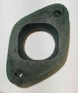
My original thought was having them lost-wax cast. To that end I hand carved a File-Wax model (below).
Here's my question: Is it possible to digitize this inner shape and then use the file to machine the parts? The material is 321 stainless steel.
Thanks
|
|
|
|
zkhennings
|
APR 16, 05:03 PM
|
|
|
It is very easy to make a lofted form from two sketched profiles on different planes. Do you have a way to measure the D shaped side of things to put it into a CAD sketch? The circular side is obviously simple to create in CAD. If you have any photoshop experience I think you could sketch the profile by hand, scan it, convert it to a layer containing just the sketch line itself, import that into CAD, make a sketch in CAD that follows the form, and then constrain it with a few major dimensions.
|
|
|
|
sspeedstreet
|
APR 16, 07:56 PM
|
|
|
Is this a place where a digitizing probe could be used?
|
|
|
|
Coolkoolpyle
|
APR 17, 02:20 PM
|
|
A probe is a bit over kill
A simple old school rubbing with a crayon and paper could be easily scanned in and turned into a template on auto cad.
|
|
|
|
Coolkoolpyle
|
APR 17, 02:24 PM
|
|
A rubbing of all three ports as they are on the head would also give a exact distance and bolt location allowing you to create a flange connecting all three ports giving a substantial increase in support and rigidity to the design and discourage cracking at welds.
A one piece design would be very superior to individual flanges for each port.
|
|
|
