
 
     |
| Fuel Level Sender/Fuel Gauge Schematic? (Page 1/2) |

|
imacflier
|
JUN 22, 09:17 AM
|
|
G'Morning, All,
Well another day another question!
I am looking for a schematic of the fuel sender/fuel gauge. Not a wiring diagram, but a schematic.
I have searched the archives and on line, the FSM, and every other source I know of without any success.
I know it is available because I recall seeing it once up on a time. SO:
Can anyone help me here?
TIA,
Larry
|
|

|
theogre
|
JUN 22, 11:21 AM
|
|
The FSM and others are correct showing 2 coils in the gauge (Under "INSTRUMENT PANEL: INDICATORS CLUSTER") but missing a ceramic resistor on back of gauge.
~ 86Ω Resistor goes between 12v and input.
Think is ½ of a voltage divider w/ the 90Ω sender and ceramic because gets warm to hot.
OP gauge in 85+ Fiero is same thing.
T-gauge has one too but wired different and different resistor value and don't have notes for that.
Set of gauge Coils are not = value but no notes on them.
All dash gauges often lie, a little to a lot, because often one to all contacts to them gets dirty, oxide layer, are loose, etc, adding or maybe reducing Total Ω ref to sender Ω.
Example: You have large plugs to dash gets "dirty" but also 3 metal clips for each does same 2 x each clip... clip to board, clip to gauge "bolt."
Gauge back Resistor "nuts" get "dirty" too doesn't help. (Don't clean the resistors! Can/will change value or wreck them and can't get new one but replace the whole gauge set.) If/when you loosen/remove the nuts, do not over tighten or will wreck the resistors. Only tighten until nut's ears are compressed.
FSM etc does same w/ other wiring w/ missing data. More so dealing w/ ECM for old cars. PCM BCM EDR ("Airbag Module") and other "boards" for other cars.
------------------
Dr. Ian Malcolm: Yeah, but your scientists were so preoccupied with whether or not they could, they didn't stop to think if they should.
(Jurassic Park)
The Ogre's Fiero Cave[This message has been edited by theogre (edited 06-22-2020).]
|
|
|
|
imacflier
|
JUN 22, 11:34 AM
|
|
theogre,
Thank you so very much....that 86 ohm resistor is key....I can probably draw my own schematic now.
But I would sure like to find one already done!
Always can count on you!
Thanks,
and
Warm Regards,
Larry
|
|
|
|
pmbrunelle
|
JUN 22, 07:39 PM
|
|
I measured 82.0 Ω on my fuel gauge resistor the other day. I don't know if 86 Ω was nominal, or was each resistor laser-trimmed to fine-tune each gauge, the resistive element then being covered over with a protective tape.
I wouldn't trust the stability of these old parts. The tachometer calibration depends on a resistor that appears to be the same style, and twice a year you have someone claiming that their engine is spinning at 4k RPM doing 60 mph.
| quote | Originally posted by theogre:
(Don't clean the resistors! Can/will change value or wreck them and can't get new one but replace the whole gauge set.)
|
|
Digi-Key has suitable replacement parts. I have the hardware to recalibrate my temperature gauge coming in tomorrow; I should be installing it tomorrow evening.
|
|
|
|
theogre
|
JUN 23, 01:55 AM
|
|
I doubt GM gave a crap about laser matching a resistor here... Fuel and OP gauge uses same pink color resistor.
Carbon Resistors often have wide to very wide tolerance... Many Carbon and other resistors have 10% to 20% tol. 82 and 86 are w/in 5% of each other. If GM Target resistor was say 84Ω, both numbers are only ~ 2.5% off.
Then add many have cheap meters or good meters but have problems reading under ~ 100Ω for various reasons. Even worse < ~ 10Ω because probe resistance etc. and many including big names like Fluke don't have a way to "tare" the meter, IE the REL button is finally getting common.
Zeroing Ω of an analog meter wasn't just solving battery issues. Even Digital meters w/ REL function that many don't use it.
"recalibrate my temperature gauge coming in tomorrow..." Is a waste of time if you think numbers on Fiero T-gauge maters. Most cars had no numbers because setup was never made to be accurate w/ number gauges and use same setup.
Even when the gauge and sender are 100% good... Any problems between them can quickly make the gauge lie to you again and often sooner then later. Every connection, wires, etc for power and "data" have to work perfect plus everything on the frame and engine for grounding the circuit must also be perfect. The "12v" is not 12v when engine is running w/ 14 to 15v from the alt. ("perfect" alt output is 14.7v but rare to see that even @ alt out terminal.) Often isn't 12v when engine is off because Full Charge battery can be 12.6 to ~ 13.1.
Related issue is OP that often lies too. I've replace the sender, update to 88 sender, replace the gauge and resistor and more and still reads higher even with fix approx 45 and 90 Ω resistors to emulate ½ and full scale at OP plug. IOW ~ 45Ω resistor reads close or at full scale 99% of time.
The only sensors even close to accurate are ones for ECM w/ Ground and Regulated 5v power directly wired to the ECM. Even they have problems and why no long make the old style ECT.
The "Bad Tach" problems is often Not the resistors but devalued or dead caps. But many just follow the famous myth to fix can just put variable resistor.
The "chip" uses RC pairs to set max swing (to match print job on front of tach) and pulse rate for given # of cylinders. Many old caps die in several ways not just crap caps made in China.
Some times is the resistor "chip" or anything else after 20 - 30+ years of heat cycling from parking in sun.
|
|
|
|
pmbrunelle
|
JUN 23, 09:16 PM
|
|
The correct use of an Ohmmeter includes touching the probes together prior to use, to see if any parasitic resistance exists in the loop. If you don't have a REL button you can do the subtraction manually. But typically I see 0.1 Ω (on Fluke, BK Precision, and whatever else I use), so this is not a problem for taking measurements in the tens of Ohms. If you have more than this, you have a problem with your setup. For lower-resistance measurements, use a 4-wire setup.
Here my resistor is installed:
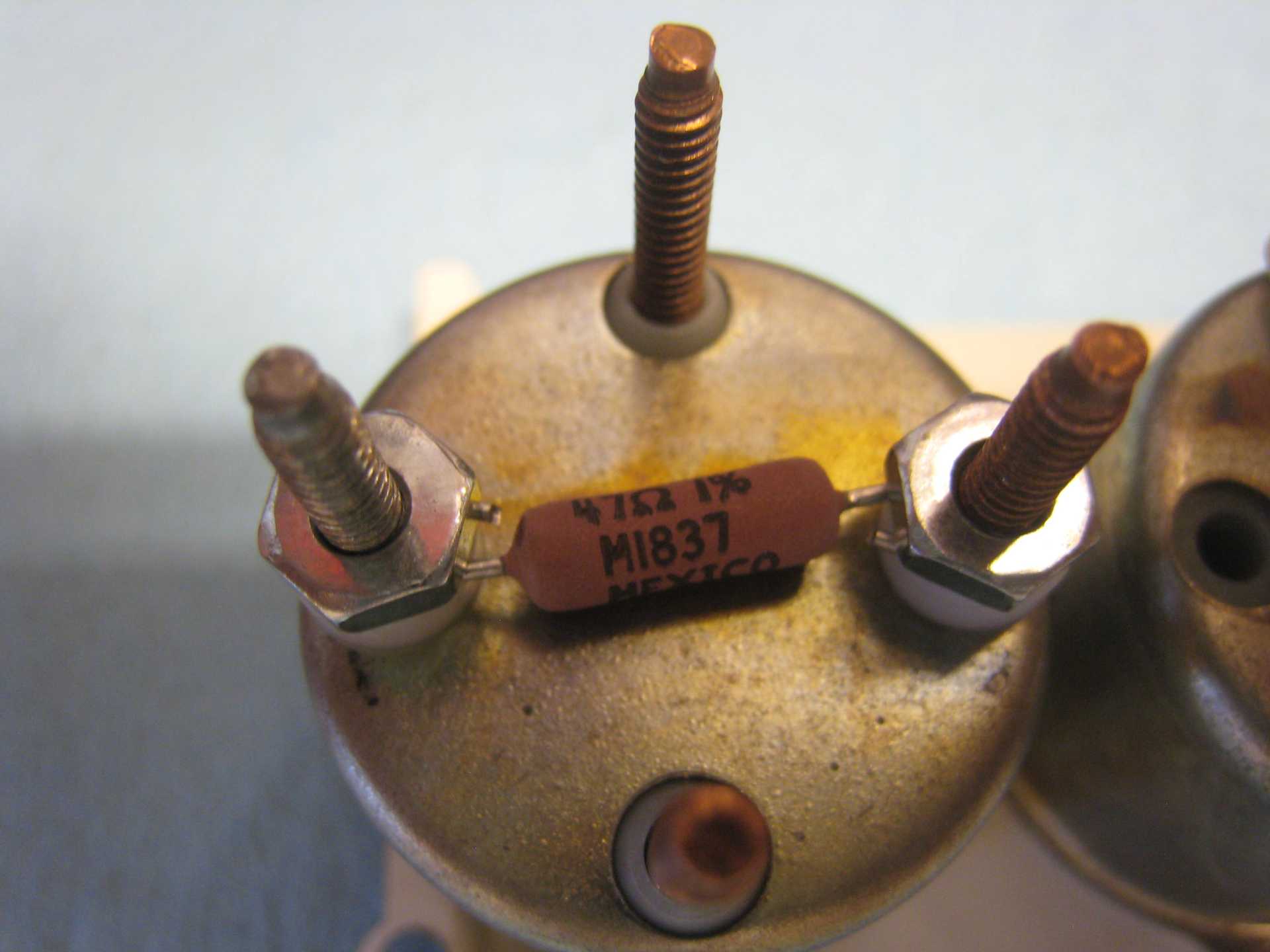
I'm not expecting perfection, but I am expecting better than what it was before! Before, the needle was either touching or in the red zone during normal driving. I don't know what went wrong, but anything is possible on a 35-year-old car. Maybe it's the aftermarket sender I used? Anyway, I will test this over the next week, comparing with the ECU's temperature reading.
To a first approximation, the fuel and temp gauge accuracy does not depend on the system voltage. For a single gauge, the needle orientation is determined by two coils, so as the system voltage varies, the currents in both coils remain proportional to each other. I guess you could add a regulator if you wanted to stabilise things more, but I don't think the complexity is warranted. I did not observe any difference in fuel gauge reading with engine running/stopped.
As for a quality tachometer restoration, you should replace both R and C. I agree that C should be changed for a film capacitor, but don't forget to change R as well.[This message has been edited by pmbrunelle (edited 06-23-2020).]
|
|
|
|
Chris Eddy
|
JUN 23, 10:29 PM
|
|
PM, that looks good, but it would be super easy to make a PCB that the resistor solders to, and then bolts on like the old style. Let me know what part number you used and I will add a new PC board design to the next order when I get boards from China.. then hand out to anyone that needs them. I could even order them with gold without breaking the bank. Boards are now SOOOOOOO inexpensive.
|
|
|
|
pmbrunelle
|
JUN 23, 11:54 PM
|
|
Here is what I used for my temperature gauge solution:
Resistor: Digi-Key ALSR3F-47-ND (I wrapped the leads around the studs and cut off the excess lead length)
#6 nylon washer: Digi-Key RPC6806-ND
Standard zinc-plated steel hex nuts, #6-32 (these were from my parts bin)
Take note that the fuel gauge resistor has some different requirements:
1. The plastic insulation around the base of the studs rises above the level of the metal can. The stock ceramic resistor includes counterbores to clear the insulation, so it can sit flat. A PCB should have large holes to clear the insulation, or should include counterbores/countersinks as appropriate.
2. When the fuel tank is empty, the fuel gauge resistor will see the full system voltage, whereas the temp gauge resistor sees a fraction of system voltage. So watch out for power dissipation.
For a PCB-based solution, I would not use a through-hole resistor like I used. Aside from being a non-standard value (for Fiero gauges), the solder joints on the bottom side would touch the metal can. Not good. So I would look at a single-layer PCB with surface-mount resistors. Possibly two in series/parallel to allow for better fine-tuning, and more power dissipation.
To keep things simple, I think you could build boards with a "GM default" resistance value, whatever that may be.
Then, people who want to fine-tune their gauge could do something like I did:
Replace the stock resistor with a multi-turn pot:
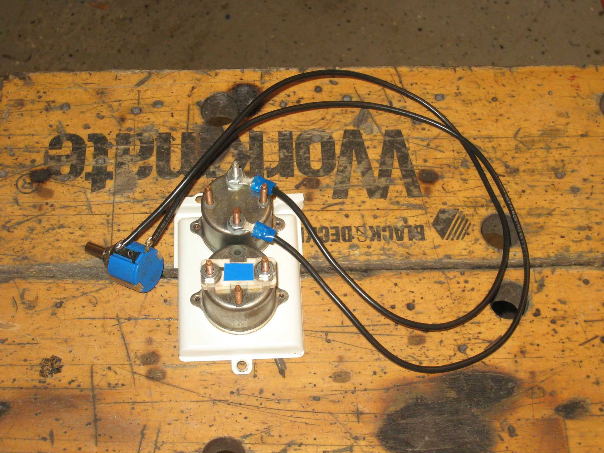
With the engine running, adjust the pot such that the gauge's reading agrees with reality:
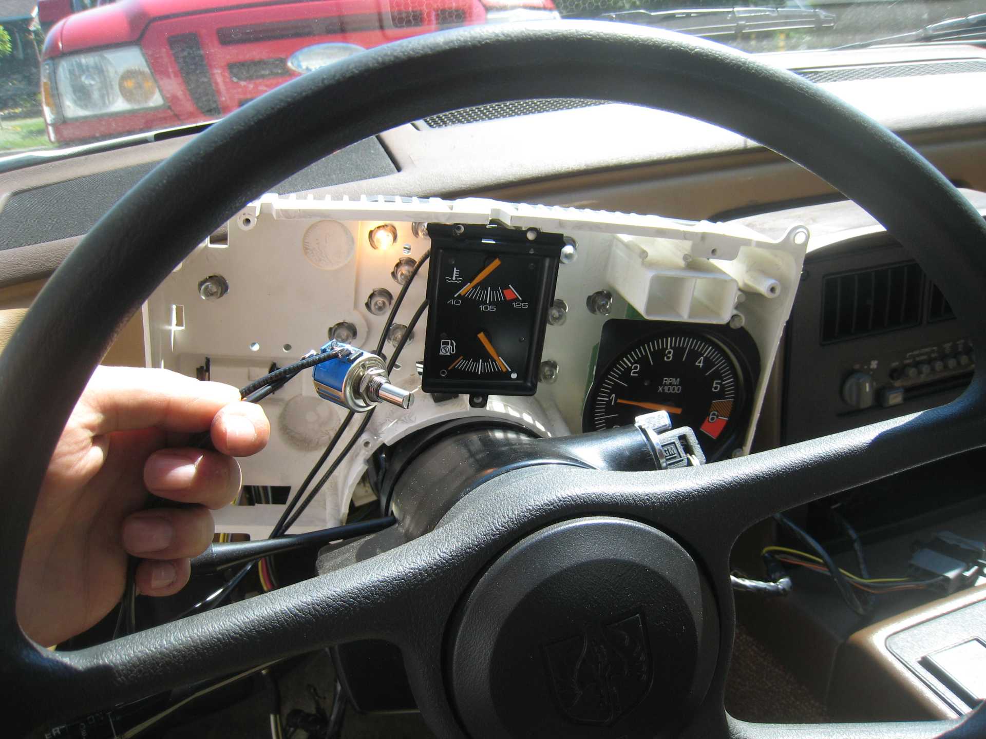
For temp, use ECU data.
For fuel, fill the tank to the brim.
Depending on the resistance that is found to be ideal, power dissipation could increase/decrease vs. the GM default resistance values, so I suggest putting the biggest SMT footprints that will physically fit, so as to give the most flexibility with regards to power dissipation. For folks who want to solder their own fine-tuned resistor values, it may be easier to hand them unpopulated PCBs.[This message has been edited by pmbrunelle (edited 06-23-2020).]
|
|
|
|
theogre
|
JUN 24, 01:51 AM
|
|
I like just using the resistor but coat ends w/ Brake grease etc. Mix metal rot can happen from air moisture. you have "steel" nuts, copper or whatever bolts, tin whatever wire. Or can use GB Ox-Gard, Ideal NOALOX and others are in electric section of Lowes, HD, that works on more then Al wired resi/commercial stuff.
pc board, even w/ gold, can have same problem w/ OE or other hardware here.
While now many PC parts are gold contacts...
Many years ago most were Not and have gold on one and whatever on other often causes many problems like most early SIMMs and sockets.[This message has been edited by theogre (edited 06-24-2020).]
|
|
|
|
Chris Eddy
|
JUN 24, 10:50 AM
|
|
Odd, I have a spare dash from a 2M4, and measured the ceramic resistor for the fuel gauge. I measure 88 ohms, with 4 wire kelvin. It has yellow paint.
The metal coating where the nuts go is clearly worn away.
And I see where the nylon insulation comes up around the stud where it enters the metal housing.. requiring a washer of some kind.The ceramic form on the bottom has recessed areas where the piece goes over the nylon.
|
|
|
|