
 
     |
| What does "Ignition" mean for Instrument Cluster Wiring? (Page 1/1) |

|
sjmaye
|
MAY 21, 06:09 AM
|
|
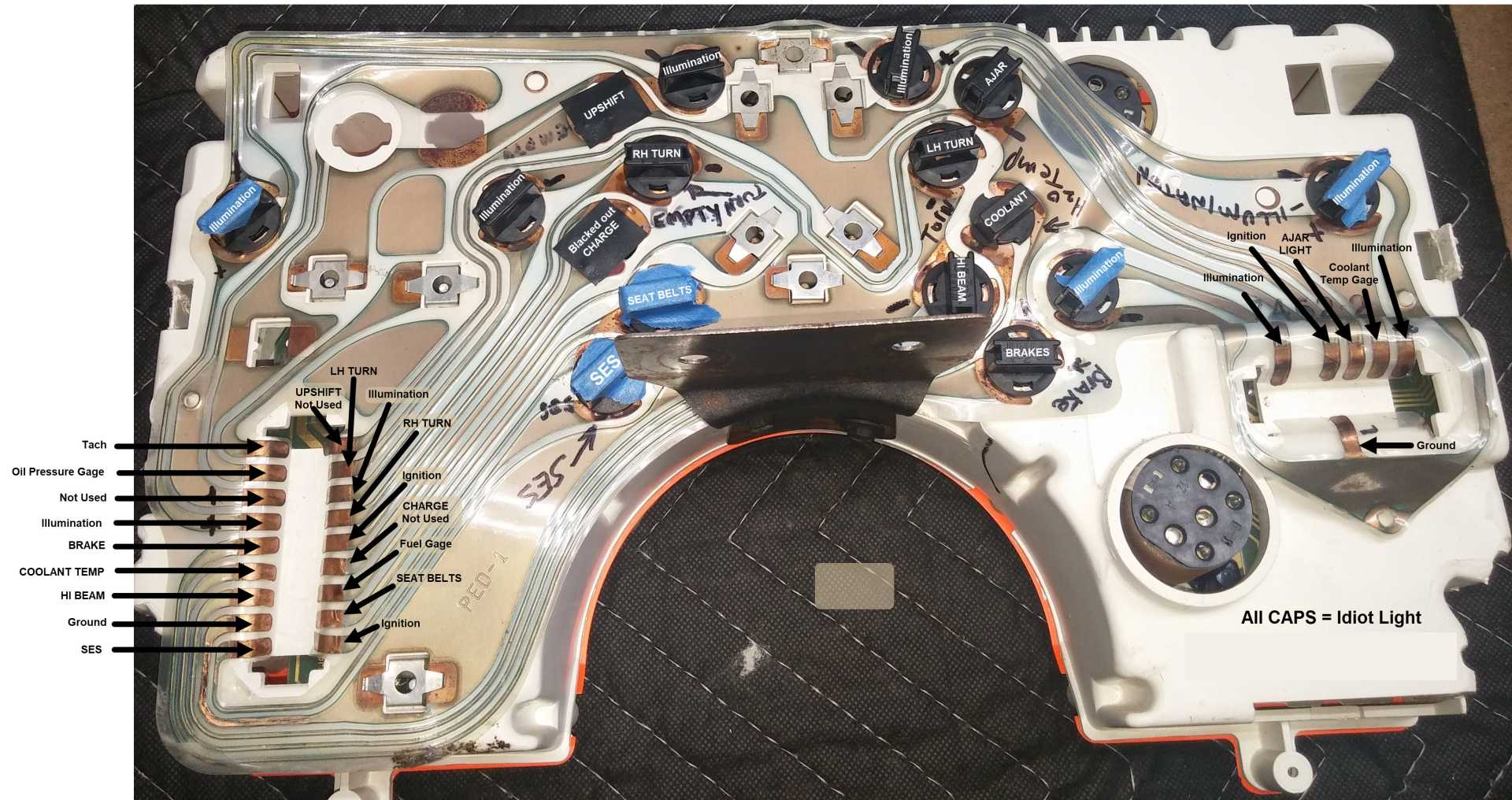
I am troubleshooting my instrument cluster. The service manual is good, but I thought a photo of the back of the instrument cluster would help me more. I am tracing the connections. The manual indicated some contacts as "Ignition". I am no electrician. In working on cars I am used to +12v or ground. These idiot lights need +12V on one side and ground (I assume) on the other. Can someone tell me why the manual calls these contacts, "Ignition"?
|
|
|
|
Cajun
|
MAY 21, 07:12 AM
|
|
|
12 volts is applied when the ignition switch is turned to the "ON" position.
|
|
|
|
sjmaye
|
MAY 21, 07:15 AM
|
|
| quote | Originally posted by Cajun:
12 volts is applied when the ignition switch is turned to the "ON" position. |
|
So, in the case of the SES light. Does that mean the SES contact is the ground and the "Ignition" contact +12V?
|
|
|
|
Gall757
|
MAY 21, 09:33 AM
|
|
| quote | Originally posted by sjmaye:
So, in the case of the SES light. Does that mean the SES contact is the ground and the "Ignition" contact +12V? |
|
Yes.
Assuming you are looking at the connector tabs at the lower left....the SES label is the trace to the SES bulb (ground side), and the 'Ignition' is switched 12 v. to the bulb (pos. side). The circuit is completed by the ECU grounding the SES trace. The 2 tabs are opposite each other on the connector, but they don't need to be. The printed circuit layout made that happen.[This message has been edited by Gall757 (edited 05-21-2020).]
|
|
|
|
sjmaye
|
MAY 22, 05:47 AM
|
|
| quote | Originally posted by Gall757:
Yes.
Assuming you are looking at the connector tabs at the lower left....the SES label is the trace to the SES bulb (ground side), and the 'Ignition' is switched 12 v. to the bulb (pos. side). The circuit is completed by the ECU grounding the SES trace. The 2 tabs are opposite each other on the connector, but they don't need to be. The printed circuit layout made that happen.
|
|
Sort of weird from my limited electrical background, but it makes sense the way you describe it. Thanks!
|
|
|
|
theogre
|
MAY 23, 11:54 AM
|
|
Could simply read http://www.fiero.nl/forum/Forum2/HTML/138175.html for most of this...
Because the picture was shot "wrong," the left C2 plug hole doesn't line up easy w/ some traces to follow them.
The other ignition on C3 is for alt bulb to turn on the alt plus alt warning if alt has problems.
Plug connects both by jumper there to design board easier.
Ignition on C2 is power for gauges and some bulbs.
2 blank bulb holes are "Spares bulbs" and should have sockets at minimum to block light leaking.
Fiero Designers had something planed for those but canceled for whatever reason. 1 N/U pin is ground to one when on. GM cut contacts to the other light to repurposed to run OP gauge.
(Even 84 has both listed as Spares bulbs but have board contacts for them going nowhere after the plug.)
Temp/fuel Gauge Clips are power, ground and "signal" for top, reverse order for bottom.
Tach clips OP, Power, Tach on top, ground at bottom. This dash must be for GT because never had OP clip. (I think 84 Dash "board" and back plastic are different and can't take OP clip.)
(84 use same warning bulb for Temp and OP)
Note that those clips are just 1 reason the dash gauges lie to you. Oxide "Rust" makes problems both on the "board" and on gauge "bolts" to plug into the clips.
Gauges have resistors bolted to back of them gets crap or loose nuts cause same problem.
Oddly the 84 docs have Illumination lights shown for temp/fuel gauges but ignore them for later years and why the other page I had to add O & P bulbs.
------------------
Dr. Ian Malcolm: Yeah, but your scientists were so preoccupied with whether or not they could, they didn't stop to think if they should.
(Jurassic Park)
The Ogre's Fiero Cave[This message has been edited by theogre (edited 05-23-2020).]
|
|
|
|