
 
     |
| Instrument cluster contacts (Page 2/3) |

|
jscott1
|
MAY 28, 10:43 PM
|
|
| quote | Originally posted by theogre:
There are minor different versions of the board over years of Fiero. Example: Some actually have contacts for 1 or 2 "spare" bulbs hidden by front of dash. (2 blank slots above the tach lights.) The big plugs just isn't wired to use them.
84 Dash may have more changes the others.
|
|
There are lots of small variations over the years, but as far as I can tell they are all cleverly interchangeable. I have disassembled dozens of them and never had a problem randomly using circuit boards from one cluster on another.
|
|
|
|
theogre
|
MAY 29, 04:01 AM
|
|
| quote | Originally posted by Chris Eddy:
I knew that The Ogre would know..
How about making a rigid (normal 1/16" 2 sided) PC board with appropriate hardware to fit.. and then use sockets with wire leads that connect to the board.
I have done many lamp boards for other projects, even designs with ultra bright 5mm LED's on the PC board.. lots of options there.
I suspect that the key reason for the flex board was the uneven surfaces plus lower cost.. a standard PC board would be a very solid fix for intermittent problems.
The existing press mate connectors would have to go.. probably crimp and poke some other type of connector to replace the existing ones. Not a reversible process.
Although it MIGHT be possible to put the contacts in for the press mate style.. the copper would go around the lip of the rectangular hole in the board, castelated style.. MIGHT be possible.
Think of the upgrade possibilities! |
|
Few if any would buy something like that to fix a dash w/ OE gauges etc. Some might buy a complete "upgrade" but would cost money few have.
Think... Take a dash completely apart and really look at how many things to connect w/ new connections.
Tach w/ OP uses clips that are push into the board and back to clip the tach board bolts. 6 more for temp/fuel gauge set. The clips just "floats" in the holes and ears are bent on back to make contact w/ the board copper.
Is not like Dash Lights sockets are made for PC use. Back plastic and board ~ = to standard FR4 board.
Other cars and more has same type sockets on full rigid boards. And Size for 194 bulb isn't only size but that's very common and used in millions of cars of many brands.
The OE "board" was not cheap to make and GM wasn't only company using same setup. The setup goes back to at lest the 70's and likely 60's.
(The plastic "film" over the id10t lights, backlit gauges, etc. were not cheap to make either.)
Yes, China board makers and others make flex boards but isn't same type of thing and likely won't last long in a car dash.
OE board and copper is made to last even w/ nubes and worse changing the bulbs. The Fact you can "simply" re-glue the copper when has plug problems should tell any that designs board the copper is far thicker then normal. Even thicker then boards for ECM Radio and many more made same time.
Again, LEDs often has issues/problems for cars did have them from the start...
Like Dash dimmer often doesn't play well w/ them. Is not simple looking in FSM etc because those don't follow real true wiring for them.
Of the very few that take time to find real wiring... 99.9+% miss the fact GM and others use NPN Power Trans on + side of the dash bulbs and Doesn't have resistor on Base of that trans too. And no, that base resistor is Not hidden inside of Knob/wheel or trans socket. Is simply not there.
Go to nearly any "book" and most will tell you put NPN or N MOSFET in ground side yet GM and other was done the dimmer in a Nonstandard way w/o "required" Base resistor. Just look in cave dimmer page. Is likely a big part of Why doesn't play well w/ most LEDs. Possibly too many LEDs and resistor w/ them can "short out" the trans and fry the trans and the dimmer "wheel" for too many mA flowing thru the Base.
|
|
|
|
theogre
|
MAY 29, 04:22 AM
|
|
| quote | Originally posted by jscott1:
There are lots of small variations over the years, but as far as I can tell they are all cleverly interchangeable. I have disassembled dozens of them and never had a problem randomly using circuit boards from one cluster on another. |
|
Likely none where 84.
84 has same light for engine temp and OP and no OP gauge or back plane for one.
GT had dash wiring for tach w/ OP gauge but most didn't have a clip there to really use a "Duke Tach."
|
|
|
|
jscott1
|
JUN 13, 02:07 AM
|
|
| quote | Originally posted by theogre:
[QUOTE]Originally posted by jscott1:
There are lots of small variations over the years, but as far as I can tell they are all cleverly interchangeable. I have disassembled dozens of them and never had a problem randomly using circuit boards from one cluster on another. |
|
Likely none where 84.
84 has same light for engine temp and OP and no OP gauge or back plane for one.
GT had dash wiring for tach w/ OP gauge but most didn't have a clip there to really use a "Duke Tach." [/QUOTE]
Yes I have used 84 circuit boards and they are cleverly interchangeable. Just like the intermittent wipers and the regular ones use the exact same harness.
The circuit boards do different things with certain traces but they are still interchangeable.
|
|
|
|
Chris Eddy
|
JUN 13, 09:24 PM
|
|
My first version of a rigid replacement circuit board is here and I did some fitment and testing. I believe that the idea will work and be reliable.
The biggest unknown is how bright the backlight will be, which must be at least as bright as the original. And whether it dims well or not.
The hard part was that the tach and double gauge modules plug into the clips. I could not easily add clips. So 6-32 x 1/2" FF standoffs are screwed onto the gauges, and inserted.. a screw fastens each point from behind. Honestly, once you get the original IC apart, it goes back together pretty quick.
I added Mini-Fit Jr connectors to the PC board. Probably the easiest plan is to make the mating connectors with 4" of wire and butt splices to join to the original wiring. Sorry, I could not keep the original connectors as I cannot figure out how to mate to them.
I have also been working with Cajun on the Riviera IC interface board, and want to get it finished before I keep going with this project. Once that is done, I will make a revised FRICB (Fiero Replacement Instrument Cluster Board) made.
I will also have to work out what the difference is with the other original version, which I do not have on hand.
I made the FRICB to match my car, an 87 2M4 2.5.
|
|
|
|
sjmaye
|
JUL 02, 03:32 PM
|
|
It has been a while. I solved my problem and wanted to come back to explain so I may help someone else.
The flicker I spoke of was nothing more than the difference between how LEDs react to power turning on and off vs incandescent. As you turn the key to the START position there is a big voltage draw as the starter kicks off. With incandescent bulbs you see a slight dimming in the idiot lights when the starter begins turning. With LED the reaction is more instantaneous. Instead of a dimming it is more like a flicker.
Everything is back together and working fine. LEDs have really brightened up the dash. Not so tired looking (dim) anymore.
|
|
|
|
Chris Eddy
|
AUG 04, 08:53 PM
|
|
An update, I proposed a rigid PC board to replace the flex, and I think that I am getting somewhere.
This is, BTW, designed for my little 2M4. I do not know what differences there are for the GT.
Pictures..
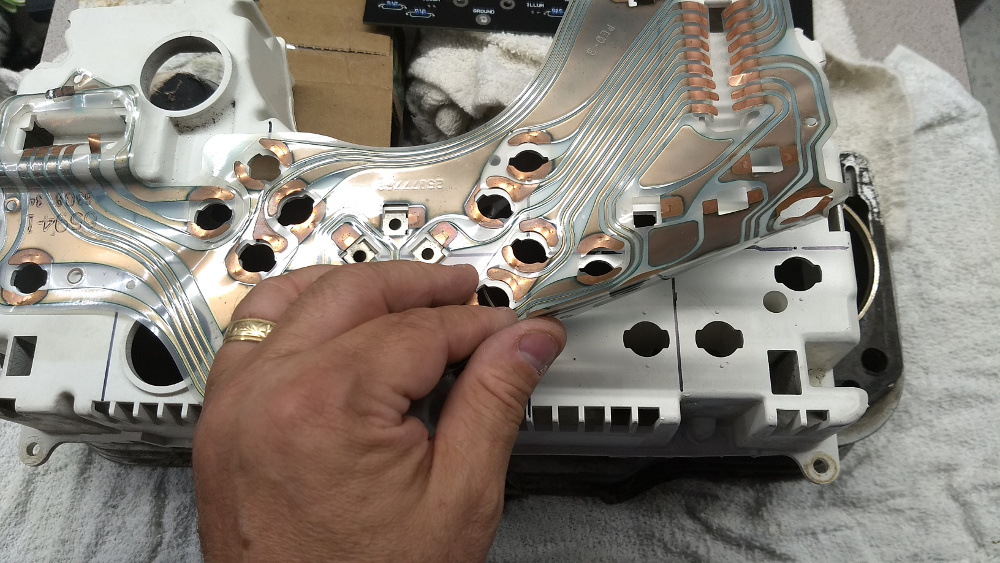
This is the original flexible circuit over the back of the plastic bucket for reference.
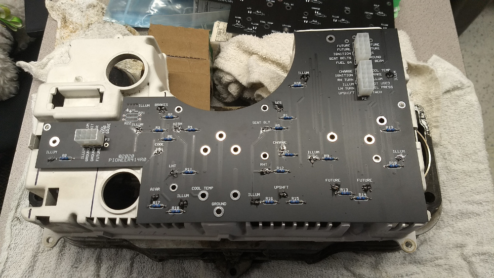
This is the PC board as it would sit on the back (there are two versions here for the eagle eyed).
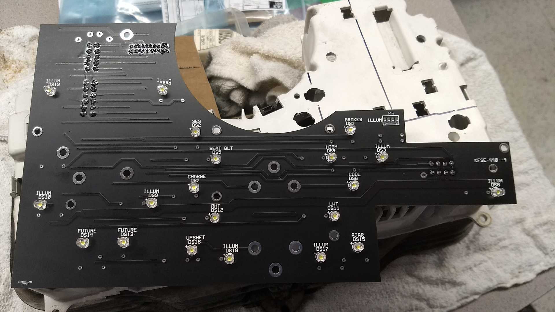
This is the PC board flipped over to show the bright white LEDs that I chose for this..
This is a closeup of two of the connectors, and the header is meant to plug in a test pod to measure things in car..
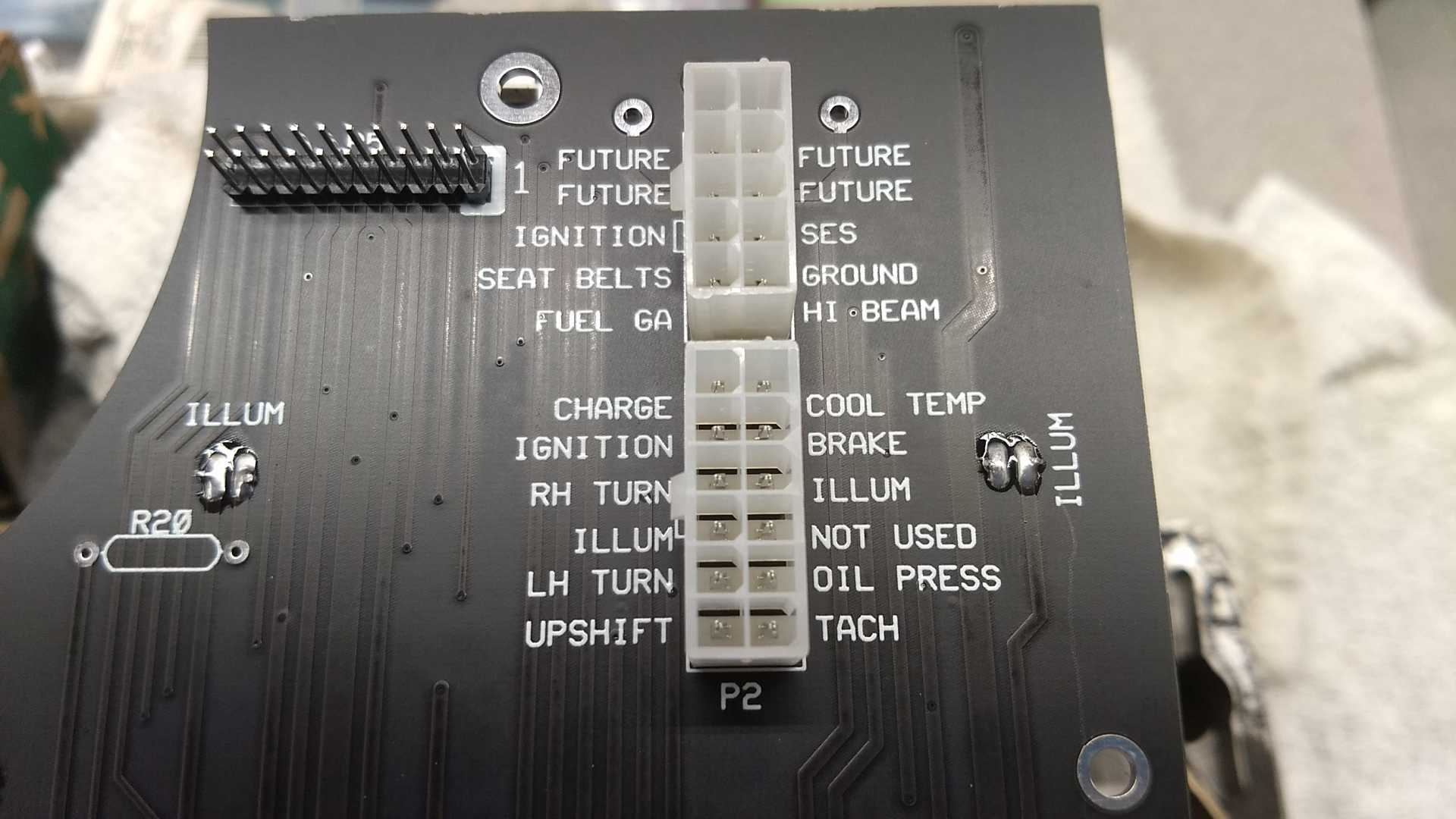
This is a closeup of the other connector on the other end.
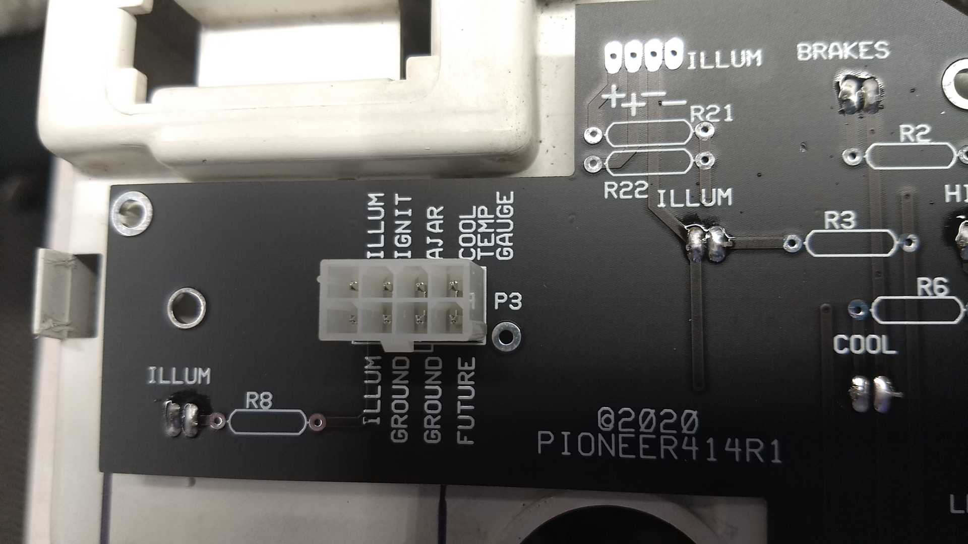
The revised board fixed subtle dimension issues, and beefed up pads for better solder joints.
The key to this was the plug in gauges. The spring loaded contacts are not going to work with this. So I put standoffs on the end of the studs on the gauge, and then a screw through the PC board attaches.
I have higher wattage resistors on the way, then can complete it, and do a very first test of LED brightness, and probably more important, if they dim easily and well.
My goal is to have a brighter backlight than before, and I added two LEDs for that.. two holes have to be drilled for them. But there were no other easy to place locations for more backlighting.
Once I get things finished, and test functionality, I will share some videos.[This message has been edited by Chris Eddy (edited 08-04-2020).]
|
|
|
|
Cliff Pennock
|
MAY 19, 05:34 AM
|
|
Holy old thread bump, Bat Man!
But whatever happened with this? This looks really, really interesting!
|
|
|
|
jdv
|
MAY 19, 08:48 AM
|
|
|
|
|
richard in nc
|
MAY 19, 08:11 PM
|
|
thats what im using.it seems great but it doen't fit the raised area well.mine seems to be working.it might need taped down.
|
|
|
|