
 
     |
| 4.6 Northstar Swap Project (Page 6/22) |

|
copperhens
|
DEC 22, 08:16 PM
|
|
I went over to Charlie's today, and picked up some stuff. He has four cool Fieros.
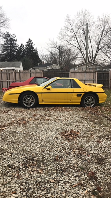
This one is a super duty.
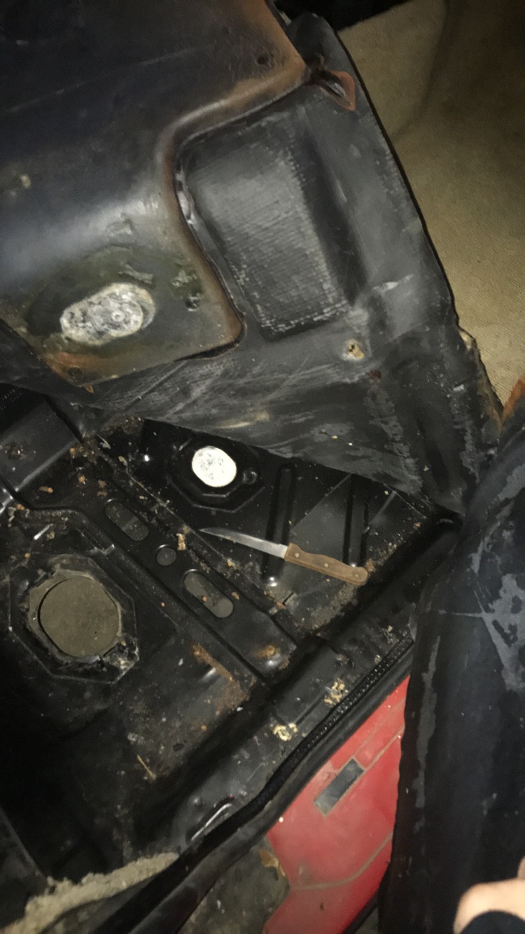
I'm debating what to do about the carpet. The car smells yucky, and according to Charlie(he's the one I bought the northstar Fiero from), it was filled of mouse poop when he got it. New carpeting is around $150, although the carpet is in pretty good shape. The foam just looks yucky. Oh well, not really an immediate concern. When I was peeling the carpet back I found something really strange.
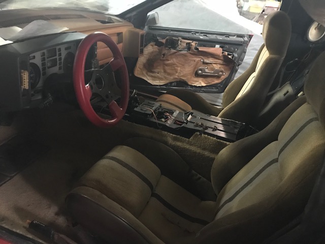
I also got some seats! I swore I had a better picture of them, but this is all I got. I just put them inside the car so my dad wouldn't have a heart attack from the garage being more messy. These seats are from an '84, so they have that stripe, and speakers! I'll need to figure out to wire those in though. The passenger seat is flawless. The driver side has two rips. but they're not worn.
|
|
|
|
fieroguru
|
DEC 22, 08:23 PM
|
|
| quote | Originally posted by copperhens:
I'm debating what to do about the carpet. The car smells yucky, and according to Charlie(he's the one I bought the northstar Fiero from), it was filled of mouse poop when he got it.
|
|
Take the carpet out and to the car wash. Clip up with the floor mat clamps and spray it down until the water coming off of it is clean. I do this to every new to me fiero.
|
|
|
|
copperhens
|
DEC 23, 08:04 PM
|
|
| quote | Originally posted by fieroguru:
Take the carpet out and to the car wash. Clip up with the floor mat clamps and spray it down until the water coming off of it is clean. I do this to every new to me fiero. |
|
Messing with my carpet seems like a spring project... I'll try to save it, as it looks pretty good on top, just stinky. Thanks.
|
|
|
|
copperhens
|
DEC 23, 08:21 PM
|
|
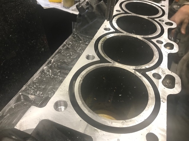
Made good progress today on the engine!
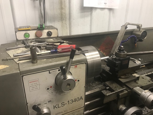
My dad and Mr. Eric are pictured here trying to align the block on the Bridgeport. This took an hour or so.
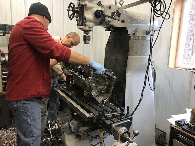
I worked on getting the cam bolts(10mm) off. They were coming off at first, and then they kept stripping, no matter which 10mm I used. I had to pound a 3/8in on to get quite a few off.
Turns out both 10mm had split.
.jpg)
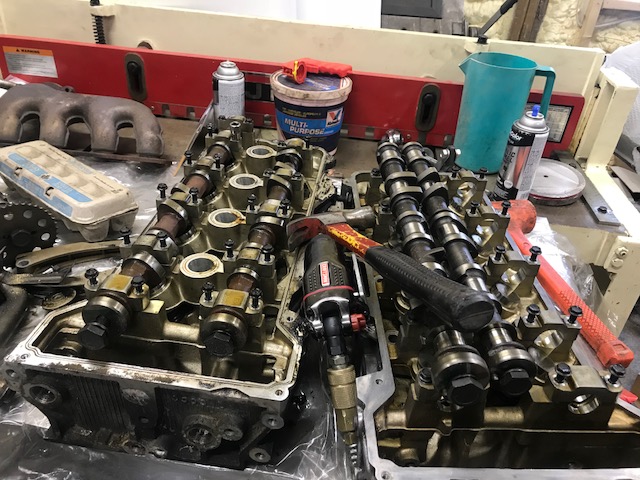
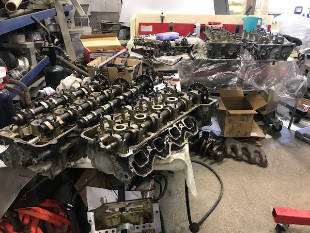
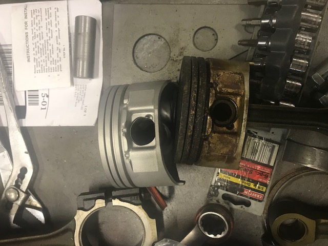
The exhaust lifters and cams on my heads were pretty awful. Luckily I not only have a spare set of lifters, but a spare set of heads too.
The surface was pretty rough, so we shaved off two thousandths of an inch.
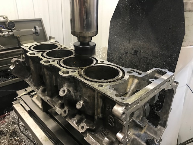
The first two holes are tapped in this picture. The Bridgeport was having some alignment issues and needs a new scale, but we still got it done. Just took a while since we had to do a lot of the math the scale couldn't. We started the taps with the Bridgeport, and finished the, by hand. We were able to get this half of the block done.
Made a temporary dowel pin for the piston so it could be bead blasted.
Looking good!
|
|
|
|
Phlebmaster
|
DEC 24, 09:03 AM
|
|
|
Nice work! I bet it feels good to get this far... The assembly will be the fun part, but then are you ready to start the swap? Thanks for the good pictures and descriptions [This message has been edited by Phlebmaster (edited 12-24-2018).]
|
|
|
|
copperhens
|
DEC 25, 01:38 PM
|
|
| quote | Originally posted by Phlebmaster:
Nice work! I bet it feels good to get this far... The assembly will be the fun part, but then are you ready to start the swap? Thanks for the good pictures and descriptions
|
|
I've been lucky so far that a lot of the custom work has already been done. My Christmas break goes until January 6th. What're the chances I'll crack down and get the engine together by then? I have all of the parts, so in theory it's possible.
The transmission situation is going to get difficult because the engine came with a stock Fiero 5spd trans, and I have an F23... So I will have to make a new trans mount for that at least. As well as the guts of the trans may differ.
|
|
|
|
Lunatic
|
DEC 26, 06:22 AM
|
|
I'm going to dump some information in this reply as it's Northstar/F23 related. If you think it's too much, let me know and I'll remove it.
I've decided to add some information to those interested in mating the Northstar to a F23 transaxle.
Notes;
1a) The Northstar has one mounting flange hole (on the bellhousing) offset to clear the 4T80-E transaxle. Therefore we will need to clearance the block for a bracket.
1b) The Getrag F23 will physically bolt to the Northstar. Although the F23 is secured to the block with six bolts while attached to the 2200 SFI or 3800 engines, on the Northstar we will use four for sure. There is a possibility to use the 5th hole.
2) Stock Fiero axles fit right in, no modifications are necessary.
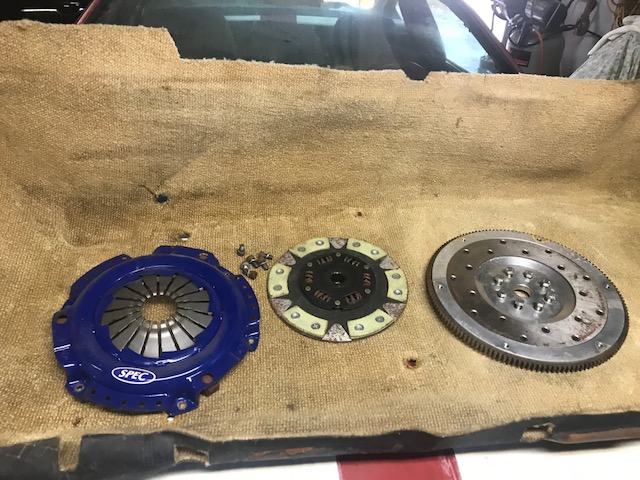
3) The Northstar is neutrally balanced. Therefore we need a flywheel that is also neutrally balanced. With some minor machining, you can use the one that came from the 2000-02 Sunfire or Cavalier. The part number for this flywheel is: 14018712. If you Google that number, you'll see it was used in many applications.
4) Fiero clutch and pressure plate can be used.
5) Transaxle mounts. You'll have to fab up some mounts as the F23 doesn't really line up with anything on the Fiero cradle.
6) Flywheel bolts. The Northstar flexplate bolts are too short to use on the manual flywheel. You'll need to find something suitable. Whatever you end up using, use Loctite and torque to the manufacture's specification. FYI: Make sure the bolts used aren't too long or they'll hit the rear bearing and either damage it, or cause the crank not to turn. The maximum length they should protrude from the flywheel is .530" The holes in the crankshaft flange are M8x1.25
7) Despite what others think, you can use the stock Fiero clutch master cylinder. But there is a catch; you'll have to make sure to measure the concentric slave cylinder travel and see if you need a spacer or not.
I'll be using a Gen 1 (93-99) Northstar block and F23 from a 2000-02 Cavalier or Sunfire with the 2200 SFI engine for this tutorial.
Here's the dirty F23 and Northstar somewhat bolted together.

In this photo, we can use the bottom left and top left bolt holes. The middle one is not tapped and there isn't enough material to do so safely. We'll leave it alone. You can also see there is ample clearance on the left side for the water log.

On the right side, this is the hole that doesn't line up. We'll take care of that later on.

That bolt hole isn't used, although it can be. I'll show that later on as well. You can see the F23 has a casting that interferes with the water log and must get removed.

Using a hack saw, remove the offending area. It only takes a minute.

Then I chose to use a sanding disk and clean up the area a little.

The water log on the right now clears.


Now we have the filler cap to deal with. It hits the water log! This means you'll have to remove the water log to fill the trans, or fill the trans then install it onto the engine. This is nowhere near ideal.

Two simple 45° elbows (not shown) will remedy this by offsetting the filler away from the water log.

Another tight spot is the right tripod. The boss on the block is in close proximity to the axle. While it does turn, I don't have the CV boot on. The boot may foul if in place. Grinding the boss looks like it'll have enough room to clear the boot. Doing it this way should work and avoid having to use a jack shaft.

Starter clearance: As we know, the Northstar has its starter in the "V" under the intake manifold. We must clearance the inside of the F23 for the starter. Using my technique with a grinder and used (therefore smaller diameter) abrasive wheel, one can make a nice looking cut.


You'll need to go in at least 1 5/8".

Your cut should like this.

The camera gives the illusion that the left side of my cut isn't enough; it is.

If your cut looked like mine, then your starter will fit.

Now the flywheel, which needs some machining. This is the one from the 2200. It has the right ring gear diameter to work with the Northstar starter. The seven holes will need to be plugged. Either machine some pins and press them in or tap and thread in some set screws. Use high strength Locktite if tapping. After the holes are filled, one must drill new holes to match the flange of the Northstar. The pattern is 8 on 78mm. The holes should clear the 8mm bolts and be around 8.2mm; a 21/64" drill bit should be good. After that, machine off the rear flange of the flywheel. It's around 0.060" thick and needs to be removed. This is because the Northstar crankshaft is larger in diameter and needs a larger base. After the material has been removed, use the spacer that came on top of the Northstar flexplate and place it between the flywheel and crankshaft. This plate is around the same thickness as the material that has been removed. Now we need a bushing made to center the flywheel onto the crankshaft. Make it a press fit into the flywheel and the inner diameter should match that of the Northstar crank.


Here's the bushing that's needed to center the flywheel onto the Northstar crank.
Note: I say "my application" below. Measure "your" Northstar crank lip and flywheel ID to get the proper measurements.
Dimensions:
The inner diameter (in my application) was: 1.102"
The outer diameter (in my application) was: 1.263"
The overall length (in my application) was: .356"


Here's a metric layout of the bolt circle, for the flywheel, that's needed when using a mill with a DRO (digital read out).

If one had access to CNC equipment, making a flywheel would be easy. Here's a few quick drawings of what it would look like.


Oh yeah, the ring gear!


If designing your own flywheel, you can pick up an aftermarket ring gear as seen below. Using the flywheel shown, it'll work with your existing starter. These are fairly inexpensive at around $40.
This ring gear is installed as a "shrink fit". Meaning one will heat the ring gear to expand it, then quickly install it onto the flywheel. As it cools, it shrinks into place. If I was going this route, I'd machine the mating surface on the flywheel around .020" bigger than the inner diameter of the ring gear. I'd say 0.002" per every 1 inch of ring gear would be an interference fit. Therefore a 10" ring gear should have 0.020" of interference. Steel expands when heated. So, for every 100° in temperature rise, you gain 0.006" of ring gear expansion. Therefore at 400°, you should be around 0.024" of expansion. I'd also place the flywheel in the freezer for a day too.
Some specs:
-Pioneer part number: FRG 142W
-Outer diameter: 11.910"
-Inner diameter: 11.088"
-Pitch 12
-Width: .453"

Addressing the mount that doesn't line up.
As seen in this photo, one can see the mount that doesn't line up.
Note: The centerline of these bolt holes is 1.0625" apart or 1 1/16".

That's okay, this is an easy fix. I used a piece of 1" round stock. Coincidentally, it had the perfect inner diameter of 1/2", which is what we need.
Note: The length of my tube was .970" (thickness of the flange) + .240" (thickness of the material) = 1.210" long.

I chose to slip a bolt through the tube that I just cut and used that to scribe a line.

As seen here, this is what you need to remove from the block.

Take your time here with the die grinder and you can make it look factory.


I also added a fillet to clear the weld.

Checking the fitment.Looks nice and like it belongs.

Oh yeah, here's the mounting lug adapter that we're making.


Here's the piece that was laser cut out of 1/4" mild steel.

Here's what it'll look like after I attach it to the tube that I cut earlier.

After TIG welding the two components, I now have this mounting lug assembly.


And lets install it.


Now for the fastener lengths. These are M12 x 1.75
Hole A = 45 mm
Hole B = Not used
Hole C = 45 mm
Hole D = 45 mm
Hole E = Not used
Hole F Upper = 30 mm
Hole F Lower = 55 mm

|
|
|
|
copperhens
|
DEC 30, 05:57 PM
|
|
| quote | Originally posted by Lunatic:
I'm going to dump some information in this reply as it's Northstar/F23 related. If you think it's too much, let me know and I'll remove it.
I've decided to add some information to those interested in mating the Northstar to a F23 transaxle.
|
|
Thanks for the info. Leaving it up is fine, in case another member has questions.
I believe I have the same trans that’s shown in that tutorial? If that’s the same one I got from you a couple months ago. The starter area is already cut, as well as the the other protruding pieces.
|
|
|
|
copperhens
|
DEC 30, 06:36 PM
|
|
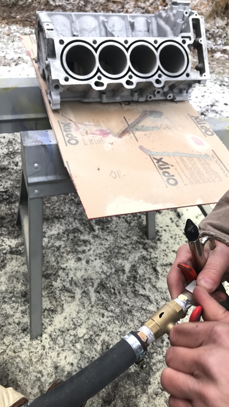
In the words of Mr. Eric, "we have some good news and bad news. The block is drilled, but its also cracked." I thought he was joking about it being cracked, by alas, it is.
It goes through the block heater, that we took out. It's not that bad, and I think it may have started when the block was cut by a PO. That curve there isn't factory. We're gonna v the crack, and weld it together.

Mr. Eric bought a sand blaster, so we tested it out on the block. It looks great.
I can't find the pictures, but two days ago when it was 50F out, I worked on the car's interior. I changed the guage cluster surrond back to tan, since PO tried to change to gray. Also took out driver side carpet, and cleaned the crap out of it. The foam was in pretty good shape.
|
|
|
|
copperhens
|
JAN 13, 06:49 PM
|
|
Still haven't worked on the block. This week hopefully.
I did take all of the transmission stuff off the seized motor today though. Apparently something in here was supposed to be broken(according to PO), but it looks fine to me. 
|
|
|
|