
 
     |
| Riviera digital Instrument cluster (IC) into a Fiero dash (Page 6/14) |

|
Cajun
|
DEC 18, 08:31 AM
|
|
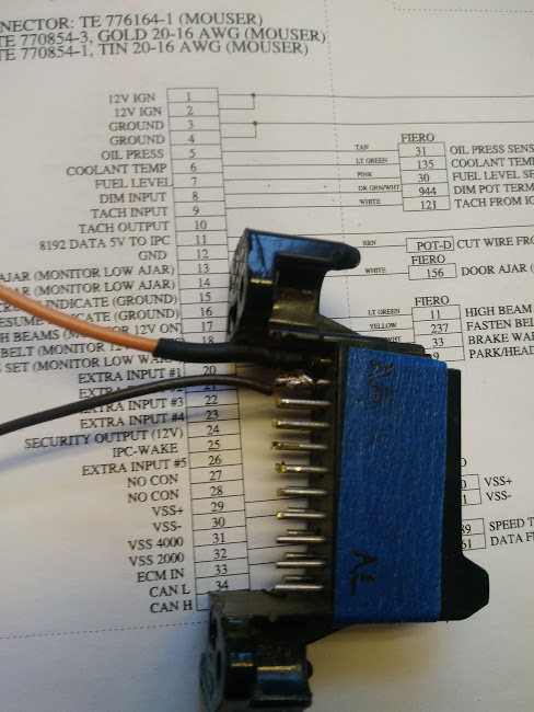
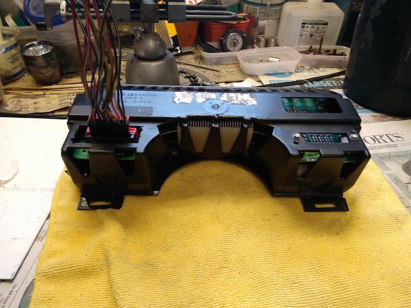
I have removed the rear connector from the spare (inop) Riviera digital IC. I am basically just testing how best to relocate the rear connector for final installation. Also testing how best to remove the connector pins that mate to the Riviera IC circuit board. For my case it would appear the best and perhaps easiest method is to heat the pins then remove when they become mobile. That is the method I will be using. Once the connector is removed I plan drill out the connector pin locations on the circuit board to facilitate the wire pigtail installation. If anyone has a better suggestion please do so!
I have begun wiring up the removed connector. I hope to follow the OEM wiring color code for the connector pigtail wiring as close as possible.
Starting the rear connector wiring mods:
Once the wiring of the rear connector is completed I will post another photo of the completed wiring job.
Happy holidays everyone and please stay safe!!!
|
|
|
|
Chris Eddy
|
DEC 20, 12:55 PM
|
|
Cajun, a comment and a question..
First, I would not drill the holes to put the wires into the circuit board. The holes are plated through, and if you drill them the soldering on top and bottom would have to be just right, and prone to failure.
Question, is it possible to shift the IC up, or forward, or both? I for one have to sit up and peer over the steering wheel to see the gauges. So a little up and forward might not be a bad thing.
Instead of the original connector from the IC, you can now choose a different male and female connector to work with instead.. something with crimped pins would be great.
|
|
|
|
Cajun
|
DEC 21, 08:49 AM
|
|
Chris,
Thanks for your comments:
Item 1: On drilling holes, I was referring to drilling out the solder on the mounted connector point once it was removed. Basically cleaning up the connection point. Currently thinking the drilling would require additional work and potentially cause other issues. My current plan is to solder wires to connector pins on the IC circuit board.
Item 2: Relocating the IC & surround. I am thinking that would open up a linty of new mounting issues. As it currently stands the Riviera digital IC fits pretty snuggly in the Fiero IC surround. Moving the surround up a bit would then require new fitment issues regarding the surround and mating components. It's doable but would require additional work and fabrication of companion components to make it look like it belongs in the new position on the dash. The IC could be moved forward a bit but not enough to allow the connector to fit. There is not really that much room for play or movement.
|
|
|
|
Cajun
|
DEC 24, 03:44 PM
|
|
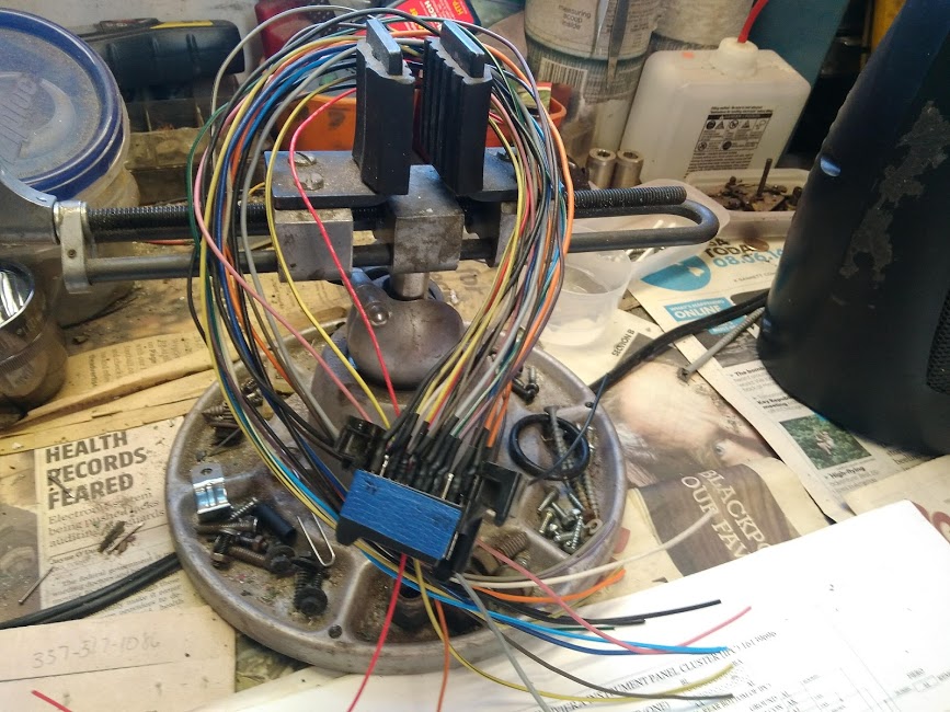
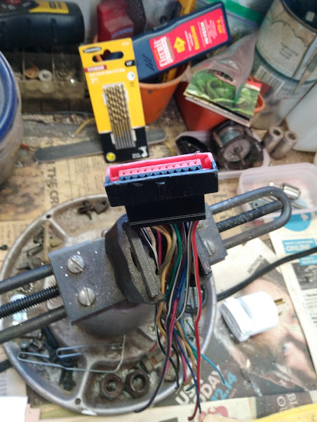
Worked a little on the Riviera digital IC rear connector modifications:
I have completed the pig tail portion of the Riviera IC rear connector modifications. Now for the real work! I also need to gather up enough courage to cut off the rear connector on a working Riviera digital IC. Once the rear connect is removed (cut off) I am pretty much committed to carry on. I just have not yet decided the best method for the removal of the rear connector. The pig tail section connector was cut off from a non-functional Riviera digital IC. I am leaning to that approach for the connector removal. Then I can remove the connector pins individually from the circuit board.
A photo of the pig tail section of the rear connector:
More than likely will not be doing any more work on the this project until after Christmas.
Merry Christmas everyone and please stay safe!!!
|
|
|
|
Cajun
|
JAN 08, 02:22 PM
|
|
I have been dreading removing the fixed connector on the Riviera digital IC. To that end I have been researching my opinions and believe me there are not many!
HOLD Da PHONE.......... have you ever had one of those aha moments when the light bulb goes off in your brain to a potential solution to a problem? My fear was the removal of the fix connector on the Riviera digital IC for connection to the rest of the vehicle. The way I removed the one that I will possibly use for my solution for the existing IC connector contacting the steering wheel mounting bracket was to cut it out with a Dremel cutting wheel. That approach worked out okay for it's intended use or purpose but not so much the removal of the fixed connector on a working IC. I'm thinking the cutting wheel action could potentially create static electricity and fry the circuit board to which it is attached?
So, I have ordered a couple pairs of micro diagonal wire cutters. The wire cutters will be used to cut the connecting pins between the circuit board and the fixed connector. There is about an inch of play or room there. If all goes well I will end up with pins sticking up from the circuit board. Those pins and their placement appear to match the mating connector for the IC. If that is the case, we will be home free on this part of the project. Cross your fingers!! Failing this approach I will go ahead and wire each pin individual to the pig tail I have already fabricated. Not my first choice.
Once the micro wire cutters arrive I will proceed with the project. Also I will take photos of what we are looking at and the end results.
Hope to be back soon..........
|
|
|
|
Cajun
|
JAN 17, 04:00 PM
|
|
Plan "B" is the route to take.....
In fact it's a method that will allow most individuals to accomplish this modification to the Riviera digital IC. No soldering necessary!
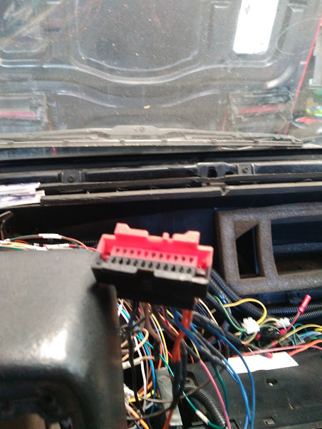
The operation is to remove the IC rear connector to gain access for the installation of the IC in the Fiero surround. By removing the connector an inch or two of clearance is gained for installation of the Riviera digital IC into the Fiero surround.
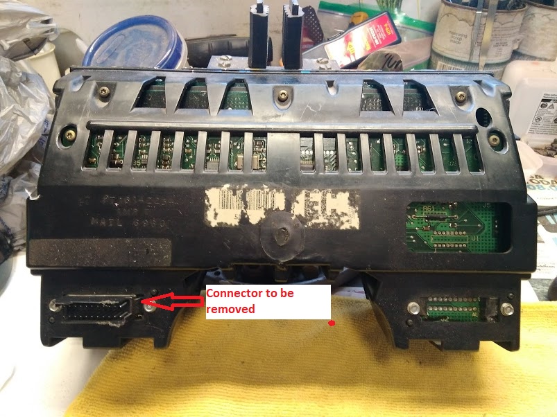
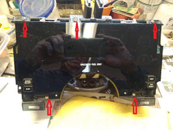
To access the IC connector & the circuit board the front and rear covers will need to be removed. To remove the covers 12 screws will need to be removed. Five Trox T-15 and three Trox T-15 and four 7/16 hex screws in the rear.
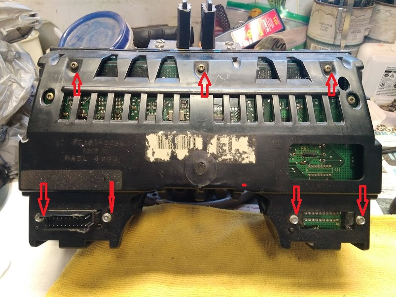
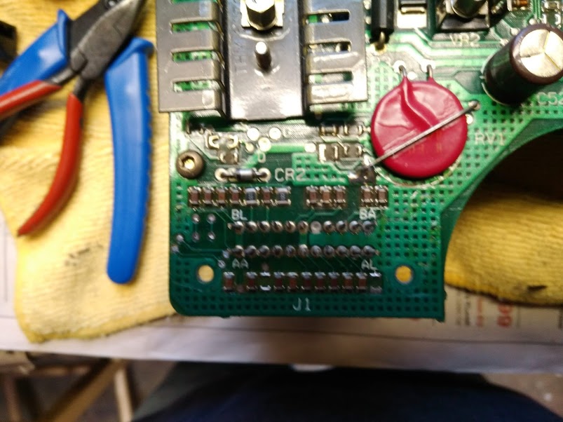
Once the rear cover is removed and you have clear access to the connector you will need to cut the pins coming from the IC circuit board to connector. Cut the pins just below the connector. I found it's best to cut the pins with micro diagonal wire cutter. The head of a micro wire cutter allows access to the individual wires (pins) from the circuit board. You will notice that in cutting the pins some may bend slightly in the cutting process. No worry, they can easily be straightened once the connector is removed.
This is what the circuit board should look like once the connector is removed. Oh, it was a ***** to removed the screws attaching the connector to the circuit board.
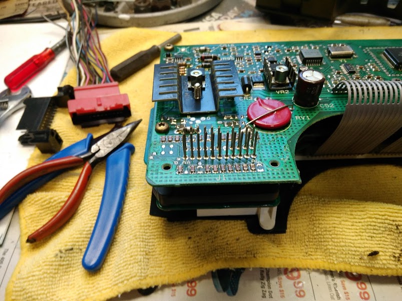
The opening where the connector was will need to enlarged to accommodate the IC mating connector.
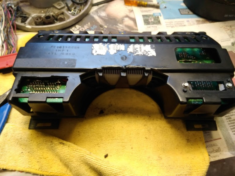
Photo of the mating connector installed. A note of caution when installing the mating connector ensure you have the proper connector orientation. The pin numbers are marked on the circuit board to aid in connector orientation.
I have not yet re-installed the surround back into my GT. I will follow up once the surround is installed.
|
|
|
|
Cajun
|
JAN 18, 03:48 PM
|
|
A little more progress this afternoon........
I have installed the Fiero surround in my GT for a test fit:
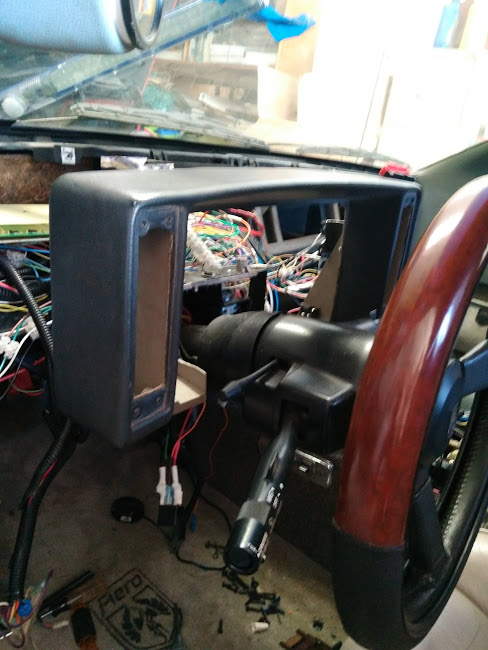
I then removed the surround, installed the Riviera digital IC and re-installed in the GT:
The following photos are various shots to the installed, back & top views. Sorry for the overhead light reflections in some of the photos:
Back view:

Top view:
In order to gain additional room for the Riviera IC connector I had to shave the lip off of the connector. I will be the first to admit the fit is tight but manageable.
Stock Riviera digital IC rear connector:
The Riviera digital IC rear connector shaved:
I have not yet powered up anything. Before that can happen I need to re-install the various connectors and switches that was removed previously. I will not be re-installing the dash until I can test the Riviera digital IC. Don't want to have to do work twice or three time before I get it correct.
|
|
|
|
Cajun
|
JAN 19, 08:02 PM
|
|
Powered up i Riviera digital IC this afternoon. Nothing happened, so I am pulling g the IC to see what went wrong. Suspect there may be a wiring error in my part?
|
|
|
|
Cajun
|
JAN 21, 12:09 PM
|
|
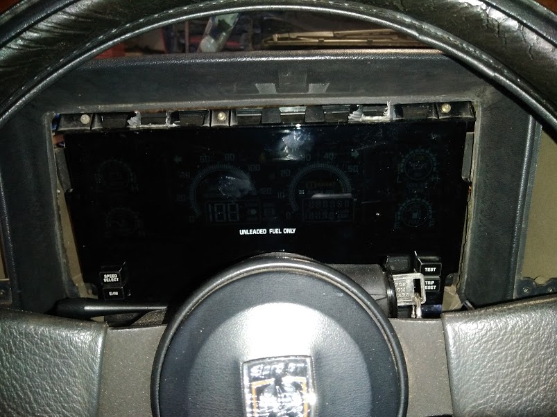
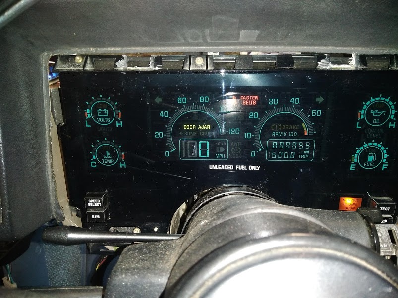
Happy days are here once again!
Went through a few electrical checks to see what I could have possibly done wrong? I removed the Riviera IC and disconnected from the car. I then connected a mating connector in order to check the various signals from the connector. All appeared to be good with the static checks; checked the various power pins and ground pins to ensure they were responding as planned.
It turns out that I have not seated the mating IC connector all the way. Once I reseated the connector and powered up. The IC lite up!!!! I made a few quick checks to see if things were working. I.e. turn signals, hand brake, door ajar, etc. Those items appear to be functioning properly. I did start the car up. The voltage gage responded as did the temperature gage. The tack does not appear to be working?
I plan on doing more checks next week. But hey, making progress. My worst fears did not happen, smoking the IC during testing!
Here is a shot of the Riviera digital IC powered up in my GT.
|
|
|
|
Cajun
|
JAN 29, 05:03 PM
|
|
The Riviera digital IC is back in my GT.
I continue to test the various functions of the Rivera IC. I still have a few indicator functions to check out before I can say the testing is complete.
Here is what is working thus far:
Turn signal indicators, emergency flasher, the gages (voltage, oil pressure, water temp and fuel level), seat belt indicator, Brake warning, cruise Resume, SES indicator, and tach.
My plans are to complete the Riviera IC testing by the end of next week, hopefully?
Photo of the IC working.......

In the above photo I was concentrating on the water temperature gage. The radiator fan started. In my mind the gage is reading a little high. When I have the Fiero stock IC in the car the temperature page never got above 200-210 degrees. I have a low temp switch installed.
This photo is where the radiator fan kicked off.

Hopefully next week I will attempt to verify the operation of the following indicators: Low Oil Level, Washer fluid, Low Coolant level, cruise Engage, Headlights suggested, Head light indicator, Security indicator.
Once all has been verified and checked I will put the GT on the road to check the speedometer function.
|
|
|
|