
 
     |
| Neil's Aventador build (Page 54/74) |

|
pmbrunelle
|
APR 16, 01:24 AM
|
|
If you're going to be re-doing this, I recommend to put the crankarm for the linear actuator adjacent to one on the hinges, not in the center. Having the crankarm in the middle of the shaft (and thus pushing on the middle of the shaft) will cause the shaft to bend like a banana.
Is this linear actuator also self-locking?
Does your software only do kinematics, or can it calculate forces as well (assuming a certain weight of the spoiler)?
With a crankarm, the linear actuator doesn't have a constant ratio; it is most effective when the actuator is perpendicular to the crankarm. So you may want to plot the required hold-up torque as a function of shaft angle, and then align the peak of the crankarm ratio with the "worst-case torque" angle.
|
|
|
|
Neils88
|
APR 16, 09:16 PM
|
|
| quote | Originally posted by pmbrunelle:
If you're going to be re-doing this, I recommend to put the crankarm for the linear actuator adjacent to one on the hinges, not in the center. Having the crankarm in the middle of the shaft (and thus pushing on the middle of the shaft) will cause the shaft to bend like a banana.
Is this linear actuator also self-locking?
Does your software only do kinematics, or can it calculate forces as well (assuming a certain weight of the spoiler)?
With a crankarm, the linear actuator doesn't have a constant ratio; it is most effective when the actuator is perpendicular to the crankarm. So you may want to plot the required hold-up torque as a function of shaft angle, and then align the peak of the crankarm ratio with the "worst-case torque" angle. |
|
Yes it is self locking and yes the crankarm is being positioned next to one of the hinges for exactly that reason (plus it keeps the linear actuator a little further away from the exhaust as an added bonus). I also switched from a hollow shaft to a solid shaft to additionally compensate for this. That particular software just does quick kinematics, though I'd design it in Solidworks and run it through Ansys if I was really worried about the specific torque-to-angle issues. I actually over designed it to begin with, so there shouldn't be any issues with this new configuration. The crankarm only has to rotate through 90 degrees, so this allows it to be positioned to minimize losses. Having said that, sadly the downforce on the spoiler isn't as much as many people would believe. They are more for show than function.
I would have preferred to keep my original setup...but I don't feel like buying another motor. Gear-motors with that amount of torque aren't cheap, and the warranty has expired on the one I had. Fortunately I have lots of linear actuators (of various specs) sitting on the shelf. Remember...design work is easy...manufacturing is always a little tougher. Sometimes one has to make compromises based on the parts and tools available. (Once the car is finished I'm putting together a CNC plasma cutter which will help a lot for future projects....just don't have the room right now).
|
|
|
|
dloyer4
|
APR 17, 12:46 PM
|
|
| quote | Originally posted by Neils88:
Thanks for the info! That is very similar to what I had in mind. I mentioned limit switches, but that was only since I was considering backup safeguards to be used to ensure power would be shut off to the motor should the angle sensor fail for some reason. Realistically, the spoiler isn't going anywhere since it mechanically stops at the two limits, but I hate the thought of driving more current into a stalled motor.  The controller will be an Arduino with a motor driver shield, so likely will keep the sensor(s) independently mounted. The hall effect sensor is obviously a nicer solution than a simple resistive rotary sensor (i.e potentiometer). I've used them before in other projects. The controller will be an Arduino with a motor driver shield, so likely will keep the sensor(s) independently mounted. The hall effect sensor is obviously a nicer solution than a simple resistive rotary sensor (i.e potentiometer). I've used them before in other projects. |
|
Rather than limit switches for end of travel, use load sensing to shut off power to the motor when a load spike from a stalled motor is detected. The benefit to this is that it will detect a stalled motor at any point in its travel. So if something happens to get caught in the mechanism - twig, stone, fingers, etc - it will stop the motor.
I personally have issues with sensors - especially mechanical sensors - in an automotive environment. Too many opportunities for failure due to environmental impact on the sensors. Hall-effect sensors are better as there's no moving parts, but their impact on the mechanism occurs, by design, at a single point, whereas triggering off the current load occurs at any point in the mechanism's travel.
In addition, swap out the motor for a stepper motor, and you can have a system that can "learn" where its limits are (with proper programming) and from that point on, will only drive excess current to the motor when something blocks the mechanism. You can also use the properties of the stepper motor to drive your mechanism to specif angles.
|
|
|
|
Neils88
|
APR 17, 06:55 PM
|
|
| quote | Originally posted by dloyer4:
Rather than limit switches for end of travel, use load sensing to shut off power to the motor when a load spike from a stalled motor is detected. The benefit to this is that it will detect a stalled motor at any point in its travel. So if something happens to get caught in the mechanism - twig, stone, fingers, etc - it will stop the motor.
I personally have issues with sensors - especially mechanical sensors - in an automotive environment. Too many opportunities for failure due to environmental impact on the sensors. Hall-effect sensors are better as there's no moving parts, but their impact on the mechanism occurs, by design, at a single point, whereas triggering off the current load occurs at any point in the mechanism's travel.
In addition, swap out the motor for a stepper motor, and you can have a system that can "learn" where its limits are (with proper programming) and from that point on, will only drive excess current to the motor when something blocks the mechanism. You can also use the properties of the stepper motor to drive your mechanism to specif angles. |
|
Welcome to PFF! 
Since I've switched over to a linear actuator, this has actually eliminated a number of the issues that I faced by using the gearmotor. Limit switches are built in, and through design, it'll open and close to the full extremes without needing to worry about external sensors to stop it. It does need a sensor to indicate when it reaches the intermediate setting (only because I didn't happen to have a linear actuator with built in potentiometer), but everything else is built in already. Using a load sensor is a good idea (especially if you fear the failure of the mechanical limit switches), and I may incorporate it at some point since it is actually relatively easy to incorporate with my control system.
Using a stepper motor is more complex...and wouldn't help eliminate the requirement for position sensors. While you can use the count to indicate position, if the spoiler were ever held up in one spot, then the count is meaningless. There are ways around that, such as resetting to a bump-stop, or having at least one limit switch to indicate a defined position. The added control system is quite a bit more complex.
|
|
|
|
dloyer4
|
APR 19, 01:26 PM
|
|
| quote | Originally posted by Neils88:
Welcome to PFF!
Since I've switched over to a linear actuator, this has actually eliminated a number of the issues that I faced by using the gearmotor. Limit switches are built in, and through design, it'll open and close to the full extremes without needing to worry about external sensors to stop it. It does need a sensor to indicate when it reaches the intermediate setting (only because I didn't happen to have a linear actuator with built in potentiometer), but everything else is built in already. Using a load sensor is a good idea (especially if you fear the failure of the mechanical limit switches), and I may incorporate it at some point since it is actually relatively easy to incorporate with my control system.
Using a stepper motor is more complex...and wouldn't help eliminate the requirement for position sensors. While you can use the count to indicate position, if the spoiler were ever held up in one spot, then the count is meaningless. There are ways around that, such as resetting to a bump-stop, or having at least one limit switch to indicate a defined position. The added control system is quite a bit more complex. |
|
Well, that's what I get for trying to hold/follow two similar conversations at once - this one, and one on arduino control of a power window system. I knew you'd switched to a linear actuator, and replied with the idea of using a load sensor, but somehow mixed in some of the power window system ideas as well...really need to focus on one thing at a time
Personally, I think the biggest benefit to load sensing is safety. Limit switches are fine for either end of the mechanism's travel, but have no way of detecting when the mechanism is unexpectedly blocked. A load sensor will detect that. Potentially protecting your motor or mechanism from damage. Or more importantly, poorly positioned fleshy bits.
|
|
|
|
Neils88
|
APR 19, 06:26 PM
|
|
| quote | Originally posted by dloyer4:
Well, that's what I get for trying to hold/follow two similar conversations at once - this one, and one on arduino control of a power window system. I knew you'd switched to a linear actuator, and replied with the idea of using a load sensor, but somehow mixed in some of the power window system ideas as well...really need to focus on one thing at a time
Personally, I think the biggest benefit to load sensing is safety. Limit switches are fine for either end of the mechanism's travel, but have no way of detecting when the mechanism is unexpectedly blocked. A load sensor will detect that. Potentially protecting your motor or mechanism from damage. Or more importantly, poorly positioned fleshy bits.
|
|
I agree. Load (current) sensors are a definite safety asset but are often overlooked. They can make a control system seem like it's more complex to put together...yet in reality they don't take a lot of effort to include. I use Arduinos for controllers since this is what they excel at. A simple amount of code, and an endless array of digital and analog sensor inputs, plus multiple digital, analog and pwm outputs. Limit switches are valuable for defined positional cutoffs, stopping the need for the motor to hit a hard stop to raise the load sensor enough to trigger a stop.
|
|
|
|
Neils88
|
APR 28, 11:32 PM
|
|
Finally got into the garage for an hour today. Not much, but didn't want to over do things having just gotten the eyes done. 
Having said that, I really didn't actually achieve anything. The plan was to cut and shorten one of the links on the spoiler hinges to improve the angle at the top setting. Unfortunately, even after shortening the maximum I could, I'm still not happy with the angle that the spoiler achieves in it's final position. Installed, it just looks like it's coming up too flat. The spoiler is supposed to go to 4 degrees and 11 degrees for the two settings. It does that, but that's assuming that the lowest setting is considered 0 degrees, and the given specs use the down position as the reference...at least that was my understanding. It's lowest setting really isn't documented anywhere (that I've found), and I had just assumed that without actually thinking about it. I suspect it's lowest setting should be a negative angle giving much more than 11 degrees of total rotation. I'll have to reassess the hinges and see if I can modify them to give a more aesthetically pleasing final angle position (ummm...plus awesome downforce from great engineering calculations...)
So....summary....I spent an hour cutting two links, re-welding them back together and essentially getting no significant change. Welcome back to the garage. 
|
|
|
|
pmbrunelle
|
APR 29, 07:32 PM
|
|
Welding right after lasik is pretty adventurous!
Perhaps you can take some "artistic license" with the spoiler angle, and do what you find is pleasing to the eye. I would consider this approach.
I would think that the parked position is unspecified, and that 4° and 11° refer to the angle of attack; the angle of the chord line relative to the wind... or if not the wind, the horizontal (perhaps more likely).
|
|
|
|
Neils88
|
APR 29, 10:03 PM
|
|
| quote | Originally posted by pmbrunelle:
Welding right after lasik is pretty adventurous!
Perhaps you can take some "artistic license" with the spoiler angle, and do what you find is pleasing to the eye. I would consider this approach.
I would think that the parked position is unspecified, and that 4° and 11° refer to the angle of attack; the angle of the chord line relative to the wind... or if not the wind, the horizontal (perhaps more likely). |
|
Yes...I had a big discussion with the surgeon on this. I was a little worried about the welding fumes but he reassured me that a week was sufficient. I still need to ensure good ventilation, etc.
I'll definitely go with artistic feeling. I'm really just aiming for "close enough"....but it still needs to look "functional".
|
|
|
|
Neils88
|
APR 29, 11:07 PM
|
|
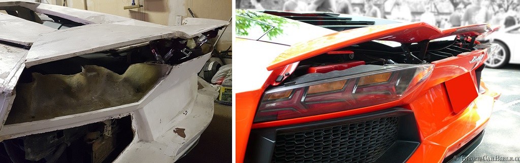
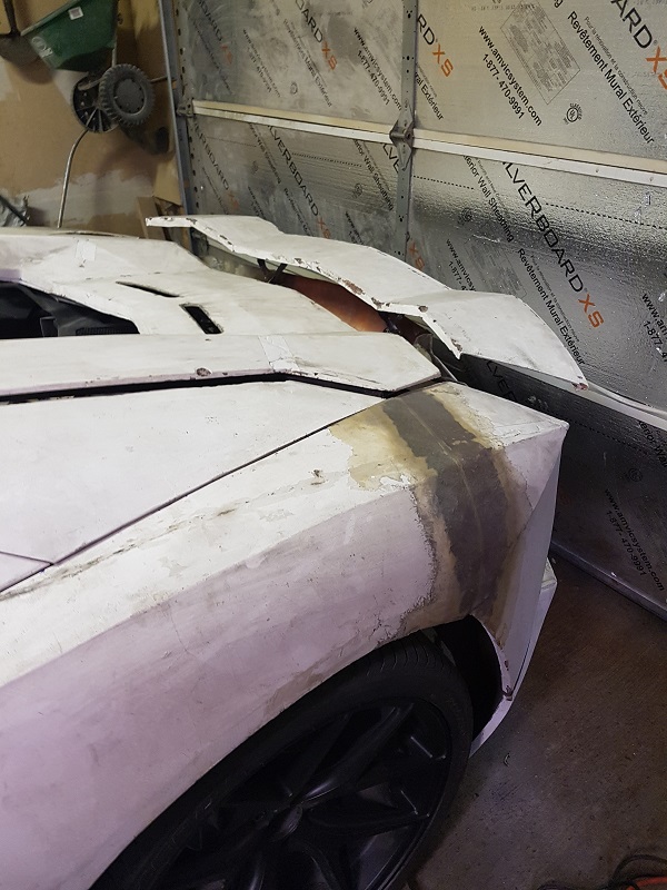
First pic more or less shows a comparison between oem and my setup. Too flat...but I'm running out of options to tweak the angle. Unfortunately, the link I need to shorten to correct this is already as short as I can make it without completely tearing the hinges apart and rebuilding them from scratch.
|
|
|
|