
 
     |
| Neil's Aventador build (Page 53/74) |

|
Neils88
|
MAR 31, 10:44 PM
|
|
|
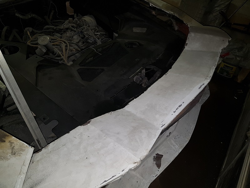
I completed welding the spoiler frame. I've also welded threaded inserts into the spoiler frame to ensure I have solid mounting points for the hinges. The hard part will be lining up the spoiler frame & hinges and then creating the required mounting points on the car's frame.
|
|
|
|
RCR
|
APR 01, 01:57 PM
|
|

Bob
|
|
|
|
Neils88
|
APR 01, 05:26 PM
|
|
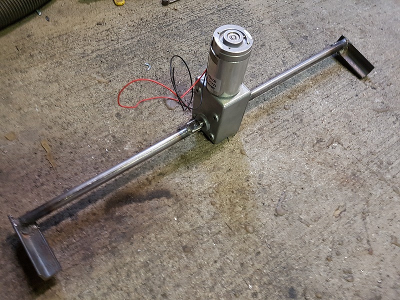
Started to put together the drive mechanism for the spoiler. It will be using a high torque, low speed geared motor. Of course I also discovered that the current framing for the bumper will be completely in the way of the drive mechanism...so, of course I'll have to make some changes to the framing. In the pics below, the spoiler framing is actually sitting about an inch and half lower than it should be. I'll set it up so that the mounting points are adjustable to allow me to easily adjust the lowest height and angle of the spoiler.
|
|
|
|
Neils88
|
APR 02, 08:27 PM
|
|
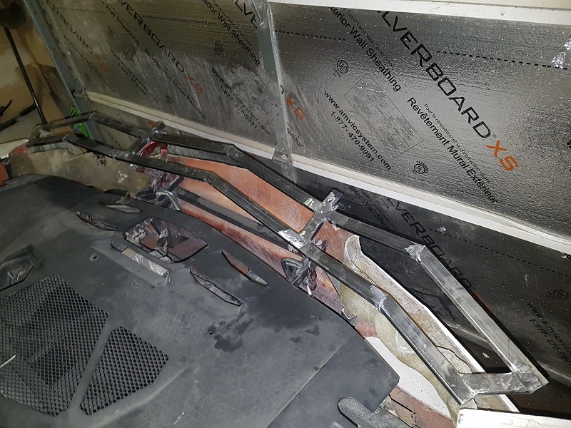
I've removed the framing that was interfering with the spoiler mechanism (also has the added bonus of getting it out of the way for the license plate lights). I'm now starting to install a couple of plates that will replace the removed framing and provide a surface for the hinges to be mounted. This gives me the ability to adjust the height and angle of the hinges easily. Lastly, once the hinges are bolted in place, I'll need to build a support bracket for the motor.
One thing I haven't touched on yet are the angle sensor, the limit switches and the motor controller that will be required. At some point I'll have to put all that together.
|
|
|
|
Neils88
|
APR 05, 09:07 PM
|
|
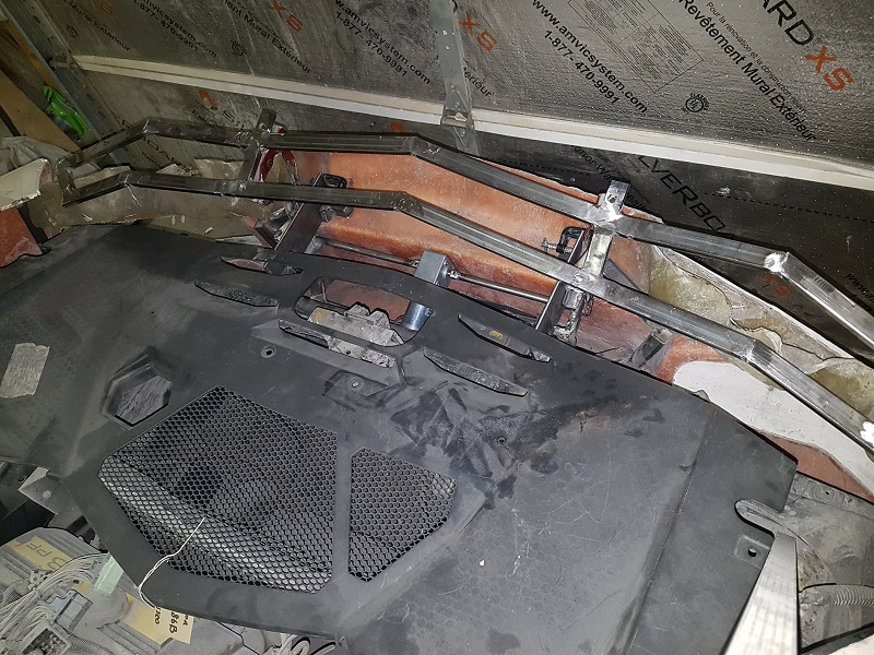
I took a few minutes to weld the adjustment plates into place for the spoiler hinges (plates can be seen in the previous pic). I can now properly align and clamp the spoiler hinges in place (to the plates)....giving me the ability to fine tune the adjustment. Almost. Before I align anything, I need to put together a bracket to mount the motor to the frame otherwise it will be the only thing spinning when I put power to it...  Of course it will need to be adjustable too since it is rigidly mounted to the spoiler hinges. Of course it will need to be adjustable too since it is rigidly mounted to the spoiler hinges.
|
|
|
|
pmbrunelle
|
APR 05, 09:35 PM
|
|
It seems to me that an end-of-shaft magnetic angle sensor would be perfectly suited to this application:

A Melexis MLX91204 PCB-mounted 2D Hall sensor would give a sine/cosine output with angle. If you need a microcontroller to control the electric motor, it could be mounted on the same circuit board; all electronics in a single module. Might not need limit switches if you can teach the required target angles.
I would use a NdFeB diametrically magnetized magnet, with dimensions on the order of:
1/2" dia
1/4" thickness
Space it at least 1/8" from the angle iron, to avoid shunting the magnetic signal away from the sensor.
|
|
|
|
Neils88
|
APR 05, 11:39 PM
|
|
| quote | Originally posted by pmbrunelle:
It seems to me that an end-of-shaft magnetic angle sensor would be perfectly suited to this application:
A Melexis MLX91204 PCB-mounted 2D Hall sensor would give a sine/cosine output with angle. If you need a microcontroller to control the electric motor, it could be mounted on the same circuit board; all electronics in a single module. Might not need limit switches if you can teach the required target angles.
I would use a NdFeB diametrically magnetized magnet, with dimensions on the order of:
1/2" dia
1/4" thickness
Space it at least 1/8" from the angle iron, to avoid shunting the magnetic signal away from the sensor. |
|
Thanks for the info! That is very similar to what I had in mind. I mentioned limit switches, but that was only since I was considering backup safeguards to be used to ensure power would be shut off to the motor should the angle sensor fail for some reason. Realistically, the spoiler isn't going anywhere since it mechanically stops at the two limits, but I hate the thought of driving more current into a stalled motor.  The controller will be an Arduino with a motor driver shield, so likely will keep the sensor(s) independently mounted. The hall effect sensor is obviously a nicer solution than a simple resistive rotary sensor (i.e potentiometer). I've used them before in other projects. The controller will be an Arduino with a motor driver shield, so likely will keep the sensor(s) independently mounted. The hall effect sensor is obviously a nicer solution than a simple resistive rotary sensor (i.e potentiometer). I've used them before in other projects.
|
|
|
|
pmbrunelle
|
APR 06, 12:06 AM
|
|
Maybe a timeout would do it; if you don't get to the desired position within 10 seconds, the show stops.
Do you think the motor will need to be powered on to keep the wing up (due to aerodynamic downforce), or does the motor have too much drag to be backdriven?
In the fully up position, the turquoise and brown links (if you extend them) pass nearly through the rotation axis of the purple link. This means that the downforce won't have much tendency to force the wing down.
In the intermediate position, there is less angle of attack, so less downforce, but the linkage is less like a "locked knee", so this is probably the worst case in terms of torque required to hold the wing up.
|
|
|
|
Neils88
|
APR 06, 11:35 AM
|
|
| quote | Originally posted by pmbrunelle:
Maybe a timeout would do it; if you don't get to the desired position within 10 seconds, the show stops.
Do you think the motor will need to be powered on to keep the wing up (due to aerodynamic downforce), or does the motor have too much drag to be backdriven?
In the fully up position, the turquoise and brown links (if you extend them) pass nearly through the rotation axis of the purple link. This means that the downforce won't have much tendency to force the wing down.
In the intermediate position, there is less angle of attack, so less downforce, but the linkage is less like a "locked knee", so this is probably the worst case in terms of torque required to hold the wing up. |
|
I specifically selected a wormgear gearbox so that I wouldn't have to worry about that. It stays locked in whatever position it is in. I can definitely incorporate a timeout function in the code...obviously much simpler than bothering with the limit switch.
|
|
|
|
Neils88
|
APR 15, 09:46 PM
|
|
Time for a little update. I've slowed down significantly due to my ongoing health issues., but I'm still getting there slowly... 
I did hit a big problem with the spoiler drive system and as a result I've modified my design slightly. While playing around with the spoiler drive mechanism I ended up damaging the motor gearbox. I didn't have the spoiler drive system clamped in place properly while I attempted to test run it. This resulted in something jamming on one side and with the amount of torque available from the motor something had to give...  It ended up causing the output shaft to "slip" in the final gear. The shaft is now slightly loose in the gear and can actually be turned almost a quarter turn with the motor stationary. This is essentially useless now. I've shelved the motor for now and switched my design over to a using a linear actuator. The rest of the design remains the same, I'm just changing the method of generating the input torque. I'll try to get the new setup up and running over the next few days. (Things will be on hold for a week or so starting next Friday since I'm getting a little Lasik... It ended up causing the output shaft to "slip" in the final gear. The shaft is now slightly loose in the gear and can actually be turned almost a quarter turn with the motor stationary. This is essentially useless now. I've shelved the motor for now and switched my design over to a using a linear actuator. The rest of the design remains the same, I'm just changing the method of generating the input torque. I'll try to get the new setup up and running over the next few days. (Things will be on hold for a week or so starting next Friday since I'm getting a little Lasik...  ) )
|
|
|
|