
 
     |
| My 1988 LFX F40 build. (Page 5/68) |

|
Rickady88GT
|
JAN 22, 09:56 PM
|
|
| quote | Originally posted by Daryl M:
Will, already checked for that. Kept the hub face perpendicular to the floor. Moved through the range of motion without moving too far in or out. I think I am OK there, but thanks for the suggestion. That would be a problem if missed. |
|
The hub face does not stay in one plane as it travels up and down. It actually goes in and out as it goes up and down. It also changes camber as well. The safest way to check is to install the drive train as guru has advised.
|
|
|
|
Daryl M
|
JAN 22, 11:55 PM
|
|
|
How many degrees does it change?
|
|
|
|
Daryl M
|
JAN 23, 12:00 AM
|
|
|
Rickady88GT why do you think there is no way to calculate how the travel of the suspension affects the axle? It's just math and geometry. It is measurable and predictable.
|
|
|
|
pmbrunelle
|
JAN 23, 08:37 AM
|
|
| quote | Originally posted by Daryl M:
It's just math and geometry. It is measurable and predictable. |
|
Well of course... but you may run into difficulties if you try to implement that strategy in practice.
You'll have to measure everything... including pick-up points on the car.
The accuracy of the result will depend on the accumulation of measurement uncertainties for each part.
Depending on the accumulated uncertainties, the accuracy may be useless for what you're trying to compute (but that's an analysis for you to perform).
Or, you can do the empirical measurement which tests the drivetrain as it shall be used.
The 3rd alternative is to roll the dice and not do any further verification.
It's up to you.
We don't have the luxury of a 3D CAD file of the Fiero, or even the paper drawings used in Fiero's design (which pre-dated CAD).
When you don't have the CAD, you have to modify your work methods accordingly.
|
|
|
|
fieroguru
|
JAN 23, 08:45 AM
|
|
| quote | Originally posted by Daryl M:
Rickady88GT why do you think there is no way to calculate how the travel of the suspension affects the axle? It's just math and geometry. It is measurable and predictable. |
|
You could spend days detailing all the critical parts of the components (tripod lobs, tripod housings, strut travel limits, pivot points for all the suspension components, etc) and then use some cad system to cycle to the limits to verify, but then the accuracy of the result will be in how precise you did the modeling. In 30 minutes or less you can verify the actual install and know exactly what you have.
The tripots are where most of the issues arise. As the angle increases, the lobes can bottom out inside the tripod housing, over extend and come out of the tripot housing, or the axle shaft could interfere with the tripot housing directly. This is why I like to do this check with the tripot boots removed and the grease cleaned out so I can better see what is going on. Iin the picture above, I actually had to cut the first set of grooves off the tripod housing to make it shorter so it would clear the axle.
A lot of people over the years skip this step and they drive the car for a long time w/o issue. Then one day they hit a large bump, go over some rough tracks, or encounter something that causes the suspension to either hit the compression or extension limit, bind the tripot, and break the tripod, axle, or transmission case. Any custom swap really should have this checked to avoid issues at a later date.
Even if everything clears, you need to leave some clearance for the drivetrain movement on the mounts under acceleration and engine braking.[This message has been edited by fieroguru (edited 01-23-2019).]
|
|
|
|
Daryl M
|
JAN 23, 12:24 PM
|
|
|
Yes, I do get the importance and the variables involved. Thanks for the feedback. I did take all of the points you have mentioned into account when making the mounts. I would be interested in how much camber does change through the span of travel of the suspension. I can't imagine it is more than 5 or 6 degrees, but I haven't measured it. I could be way off.
|
|

|
Daryl M
|
JAN 23, 12:40 PM
|
|
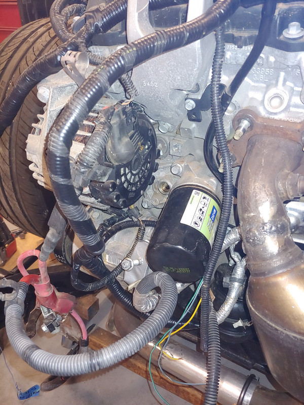
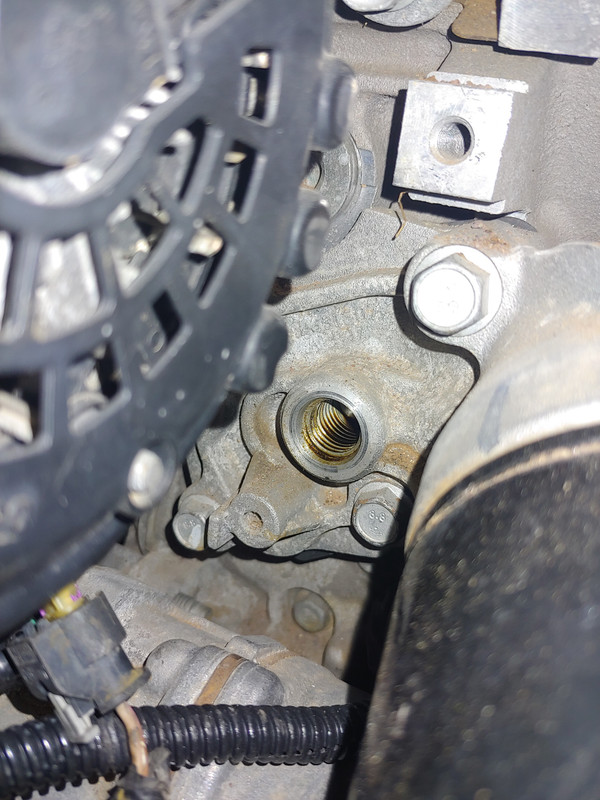
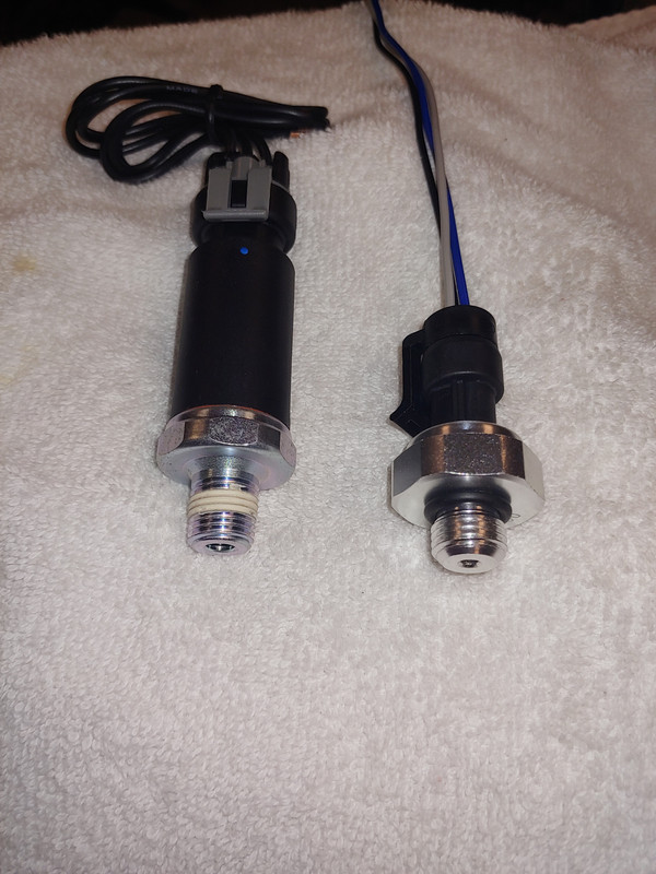

Next issue, the LFX from the Impala had a 2 wire oil pressure sender. The new programming on the ECM calls for a 3 wire unit. I think the 2 wire is for cars with idiot lights and the 3 wire for a guage. I'm showing photos of the engine where the sender lives. As it turns out I now need two senders, one to feed info to the ECM and one to feed the Fiero oil pressure guage. Also, the original Impala sender had 16mm threads, the Camaro that I have to use to match the ECM is 14mm. The Fiero sender is 14mm tapered pipe thread I think. I ordered the adapter shown to adapt the Camaro sender, but am still considering my options for where to put the Fiero sender. As I see it one option is to drill and tap one side of the adapter and mount it there. Does anyone have other ideas? Are there other places on the LFX that can be used for oil pressure?
Thanks in advance for your help.
|
|
|
|
Will
|
JAN 23, 01:28 PM
|
|
|
Do you not have diagrams? Why are you not certain where that wire goes? If the Camaro sensor has a 0-90 ohm pressure transducer in it, it should drive the Fiero gauge just fine.
|
|
|
|
Daryl M
|
JAN 23, 02:24 PM
|
|
Will
I'm not wondering about the wires. I want to know if there is another place on the engine to get oil pressure from. Two sensors at the stock location is a bit tight space wise.
|
|
|
|
Daryl M
|
JAN 23, 02:27 PM
|
|
|
Will, are you saying that using one transducer to feed the ECM and the stock Fiero gauges will not interfere with one another?
|
|
|
|