 
     |
| HELP -1988 GT V8 Swap - Oil Pressure, Water Temperature, and Gas Gauges Not Working (Page 4/5) |

|
V8Steve
|
JAN 12, 04:14 PM
|
|
Fred,
Nice ride. Thanks for your input. You are right about powder coated components. I checked the sensor housing ground to the manifold and then to the block and then to the chassis. All OK. We've got "00" size cables running from the up front battery to the starter and to the block. From the block there's another short "00" size ground cable to the chassis. These heavy cables were all used to minimize starting voltage drops during cranking.
|
|
|
|
V8Steve
|
JAN 15, 10:41 AM
|
|
|
Back on water temperature - I'd bought a new connector pigtail to reach the sensor back when I rewired the engine bay and eliminated the C500.. The OEM wires are light green and dark green but I recall not paying any attention as to how they should be connected to the two black ones on the new connector. I found an online repair site that noted they are different and if they're reversed the gage will stay on cold. So, next chance I get I'll change them and see what happens.
|
|
|
|
olejoedad
|
JAN 15, 01:10 PM
|
|
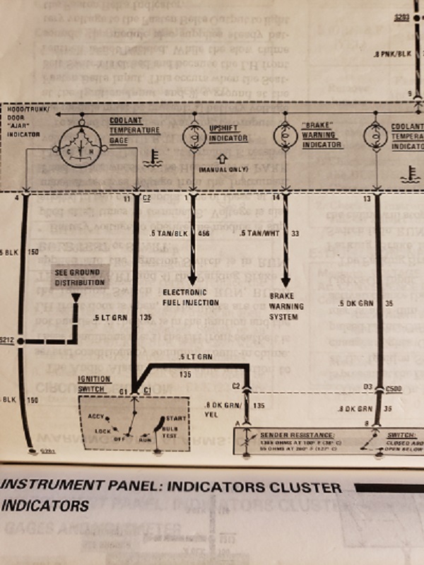
Use your meter and check which pin has resistance to the sensor shell.
That is the pin that controls the gage.
The pin that shows no continuity to the sensor shell is the pin for the switch that controls the HOT lamp.
|
|
|
|
V8Steve
|
JAN 15, 04:33 PM
|
|
The FSM shows Pin #11 is a direct line to sensor pin for controlling the gage. The cluster is on the bench so it seems a simple matter to check the continuity all the way from Pin #11 on the C2 Pinout to the sensor pin. By doing this I should be able to 1st verify continuity and 2nd to verify the correct sensor pin. I should be able to do this with the cluster on the bench and battery disconnected. Am I right?
 [This message has been edited by V8Steve (edited 01-15-2020).]
|
|
|
|
olejoedad
|
JAN 15, 05:23 PM
|
|
|
|
|
V8Steve
|
JAN 15, 10:02 PM
|
|
Water Temperature Progress - I checked the new sensor and could not get any reading from any pin to the shell. It was 35F in the shop so I brought it in the house and immersed it in 140F water. Same result with no reading from any pin to the shell. Then I took a reading across the two pins in the 140F water and got 800 ohms. I'm using an AC Delco 213-928 and now I think it's the wrong one and that this one is meant for the computer. It was always a two wire sensor but I think this one is temperature only and not meant for gauge and switch. The Holley ECU is connected to what appears to be the same sensor and a laptop shows coolant temp as it should.
Before I can troubleshoot the wires and test them, I have to have the right sending unit.
Does anyone know the correct two wire sending unit PN? Is it ACDelco 213-69?[This message has been edited by V8Steve (edited 01-15-2020).]
|
|
|
|
V8Steve
|
JAN 16, 01:45 PM
|
|
Temperature Gage - I traced both wires from the cluster back to the engine bay and there is continuity on each one. The temperature sending sensor and new pigtail are not easy to find so I ordered both from the Fiero store. I'll check the unit with a meter upon arrival. I think I'm now all set as long as the correct part arrives. Before ordering it, we had a phone conversation to be certain it's the correct one with mating pigtail. Since one of the green wires passed through the S500 connector and I'd eliminated the entire connector, I'm happy that there are no new problems.
The engine bay wiring was a real mess with duplicate wires, wires going nowhere, wires too short, wires too long, etc. So far, everything is OK and I've not found any mistakes. I'd gladly share my experience to anyone attempting this. There are PFF threads showing the same and I followed those as well.
It's too cold to take out the fuel tank now so the next step is check out this temperature gage, run the car, etc. If all goes OK, now that the tach and oil pressure gage are also working, it will be time to reassemble the cluster and the entire center console. Inside the console is a Dakota Digital module to adjust the VSS for the F40 swap. Right now, that's the least of my concerns.
|
|
|
|
olejoedad
|
JAN 16, 01:52 PM
|
|
Good progress.
Congratulations!
A lot of confusion has been caused by parts store computers calling out the wrong sensor for the water temp gage/hot lamp.
You are not the first to encounter this, and I'm sure not the last!
|
|
|
|
V8Steve
|
JAN 18, 08:37 AM
|
|
The correct water temperature gauge/light sensor along with the matching pigtail all arrived from the Fiero Store. The sensor checks out correctly with the meter. Once this cold weather warms up the project will continue.
Before the instrument cluster goes back in, I'll check it at night to make sure all the bulbs and everything else works while I have it out.
The progress with the temperature gage has given me confidence in reading the FSM and troubleshooting. Next steps will include checking out all the lights, flashers, etc. to be sure everything works. The car has rebuilt calipers all around and a stainless brake line kit. The hand brake cables are new but I have to adjust the levers in order to get it working. It's another learning process.
|
|
|
|
olejoedad
|
JAN 18, 09:41 AM
|
|
From the factory, the Fiero temp gage circuit was wired incorrectly, causing the temp gage to peg when the key is turned to the ON position.
The easy way to fix this is to pull the contact with two small gage light green wires from the ignition switch on top of the steering column. Be sure to insulate the exposed metal on the contact after pulling it to prevent unintentional grounding of the contact, it will cause the gage to peg.
|
|
|
