[This message has been edited by Spadesluck (edited 01-18-2023).]
fieroguru
JAN 18, 09:02 PM
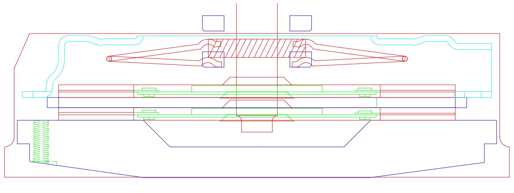
I made this drawing when I designed another flywheel around a twin disc clutch. The 4 blue rectangles are the throw-out bearing in the fully compressed and fully retracted position. The pressure plate fingers are with the clutch engaged and disengaged. Notice there is a gap between the fully retracted throw-out bearing and the fingers when the clutch is engaged - this must be there as the fingers will move closer to the transmission as the discs wear. Also notice that the finger position in the released position is before the throw-out bearing reaches the end of its travel. These are the things you want to verify for your HTOB setup.
You don't need the picture, but it might help people visualize the concepts of HTOB range of motion relative to the pressure plate finger positions.