
 
     |
| 85 Speedo, 4000 PPM output possible? (Page 3/3) |

|
pmbrunelle
|
AUG 27, 10:43 PM
|
|
| quote | Originally posted by TGYK256:
Thank you for the reply! I do apologize about the unlabeled components- I caught it just after I hit the post button.. As for the FET-switched signals for level shifting, according to the I/O schematic for the 1226864/1226156, the VSS input to the ECM from the speedo is pulled to 12v by a 5.1k resistor inside the ECM, and the speedo board triggers to ground through a transistor for signal formation. Along those lines, I am assuming a 0-12v square-wave.
|
|
I can confirm that the 2000 PPM output to the ECM is a switched ground (the transistor next to the 1 mF GLASS capacitor in your speedo schematic), pulled up by the ECM. I investigated this when I had to configure an aftermarket engine computer to accept input from the Fiero speedo.
We don't know what the cruise control module expects as input. I would suggest powering up the cruise module; if you measure a voltage at the 4000 PPM input, then you could conclude that their is a pullup resistor to the measured voltage. If you connect the input to ground through an ammeter, then you could figure what the cruise control has for a pullup resistor, if equipped with one.
| quote | Originally posted by TGYK256:
I had also considered using a resistor/zener dropper for a crude 5v supply, but figured that would be less stable than a linear regulator, require even more filtering, be less energy efficient, and likely end up costing more than the regulator + caps.
|
|
An off the shelf regulator would work. Using more discrete parts is just how they did things back then.
I would tend to the resistor/zener setup if I wanted to keep things period-correct on a classic car 
| quote | Originally posted by TGYK256:
The operating frequency range of the 4k ppm signal will be around 20-90 Hz, corresponding with a 20-80 mph range, and I hadn't been sure how that corresponds to capacitance value for filtering. Hoping I don't need to use an RC LPF to prevent harmonics. |
|
Note that most equations relating to filter attenuation are applicable to sine waves.
A square can be considered to be made up of a series of sine waves added together:

So, a 90 Hz square wave could be considered equivalent to a combination of a 90 Hz sine wave + 270 Hz sine wave + 450 Hz sine wave + 630 Hz sine wave, and so on...
If you have a filter that passes 90 Hz sine waves, but blocks 270+ Hz sine waves, then the square wave won't look like a square wave anymore once it goes through the filter; all that would remain is the 90 Hz sine!
Without going to deep into math/calculations, a good approach if you're making a PCB is to leave an empty footprint available for a capacitor, if needed. Then, you can make tests, and slowly increase the capacitor value, and see what it does to the signals (looking at the oscilloscope).
|
|
|
|
TGYK256
|
AUG 28, 02:03 AM
|
|
| quote | Originally posted by pmbrunelle:
I can confirm that the 2000 PPM output to the ECM is a switched ground (the transistor next to the 1 mF GLASS capacitor in your speedo schematic), pulled up by the ECM. I investigated this when I had to configure an aftermarket engine computer to accept input from the Fiero speedo.
We don't know what the cruise control module expects as input. I would suggest powering up the cruise module; if you measure a voltage at the 4000 PPM input, then you could conclude that their is a pullup resistor to the measured voltage. If you connect the input to ground through an ammeter, then you could figure what the cruise control has for a pullup resistor, if equipped with one.
|
|
I took your advice and did probe my "V8" labeled digital cruise module at the VSS input, I surprisingly found a voltage at 5.7ish volts. While this is good to know (We don't need to pullup the VSS line to 12v like how it is done in the Fiero.. Furthermore, doing so might cause the magic smoke to do its' thing.) I don't think I will be sinking the current directly with the ATTiny85. The measured voltage is close enough to the listed max (VCC + 0.5V) input voltage that I would rather err on the side of caution and drive via a FET. I didn't measure the current just yet, but will do so before finalizing the design- I want to make sure I don't overcurrent the FET.
| quote | Originally posted by pmbrunelle:
An off the shelf regulator would work. Using more discrete parts is just how they did things back then.
I would tend to the resistor/zener setup if I wanted to keep things period-correct on a classic car
|
|
I definitely agree, especially for the cost of ~1-2 bucks per regulator on digikey for small quantities.
| quote | Originally posted by pmbrunelle:
Note that most equations relating to filter attenuation are applicable to sine waves.
A square can be considered to be made up of a series of sine waves added together:
So, a 90 Hz square wave could be considered equivalent to a combination of a 90 Hz sine wave + 270 Hz sine wave + 450 Hz sine wave + 630 Hz sine wave, and so on...
If you have a filter that passes 90 Hz sine waves, but blocks 270+ Hz sine waves, then the square wave won't look like a square wave anymore once it goes through the filter; all that would remain is the 90 Hz sine!
Without going to deep into math/calculations, a good approach if you're making a PCB is to leave an empty footprint available for a capacitor, if needed. Then, you can make tests, and slowly increase the capacitor value, and see what it does to the signals (looking at the oscilloscope). |
|
I had heard of Fourier stuff before, but I guess I failed to connect it to the concept of filtering. My inexperience is really showing! I think that I will definitely leave the output filter cap in the schematic with a TBD value, as well as a blank spot on the PCB for testing. I feel like the frequency of the signal is low enough that I shouldn't have to worry too much about reflections and harmonics, but this is based entirely on a gut feeling. My main concern is for switching-noise spiking voltage on the rising and falling edges of the signal.
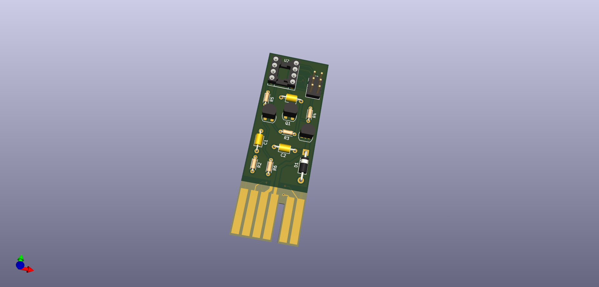
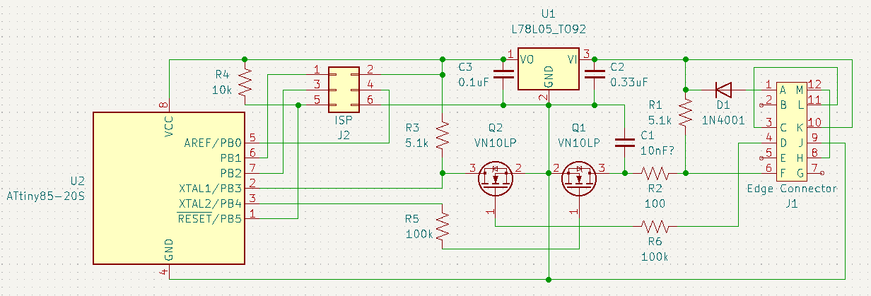
As an update, I removed the 12v pullup from the schematic and spent several hours fumbling my way through putting together a PCB. Note that in the image, I forgot to disable the model for the C1 cap before snapping a pic.
|
|
|
|
pmbrunelle
|
AUG 28, 07:49 AM
|
|
| quote | Originally posted by TGYK256:
|
|
R5 and R6 seem to have very high values. The MOSFET gates are capacitive; together with the 100 kΩ resistors, this will slow down the turn-on/off times.
What is the function of these resistors? Is it so that the driving circuitry doesn't see the MOSFET gate load when switching? They kind of seem high, I think I would go for 10 kΩ. At 10 kΩ that shouldn't bother anything connected.
Another common practice in automotive is to protect PCB connector pins against electrostatic discharge. For instance, you walk across the floor, pick up some charge, then touch the edge tabs, and you zap your circuit.
The gate of Q2 is fragile and is exposed to the outside world. It gets zapped at 20V. An "SA10A" TVS from its gate to ground could protect it. In automotive (today at least, maybe less so in Fiero times), a TVS diode is commonly used to protect PCB connectors from the outside world.
The drain of Q1 is less fragile, as it can handle 60V. I think the connector pin "F" could be protected with a "SA30A" diode. This one can conduct at a much higher voltage and really have no effect in normal operation.
A static discharge at the power input can be partially absorbed by C2, so a TVS is less important here, but you could also use the SA30A here at pin "K".
Static protection is not mandatory for the hobbyist, but if this is omitted, then you need to be more careful about grounding yourself before touching the connector pins (something that doesn't necessarily happen in an automotive factory) or the associated harness.
| quote | Originally posted by TGYK256:
I kinda really like the no-splice/no-cut mod idea |
|
How does this work? It plugs into the unused contacts of the speedo connector?
| quote | Originally posted by TGYK256:
If I get it to work, I'll release the code for the MCU, as well as the full KiCad project open-source on GitHub. |
|
Cool, link to the repo here when you're done. PFF is the biggest gateway to Fiero information, so if anyone needs to find that information, they would most likely find it through here.
|
|
|
|
TGYK256
|
AUG 28, 11:50 PM
|
|
| quote | Originally posted by pmbrunelle:
R5 and R6 seem to have very high values. The MOSFET gates are capacitive; together with the 100 kΩ resistors, this will slow down the turn-on/off times.
What is the function of these resistors? Is it so that the driving circuitry doesn't see the MOSFET gate load when switching? They kind of seem high, I think I would go for 10 kΩ. At 10 kΩ that shouldn't bother anything connected.
|
|
You guessed correctly in my intention, I don't want to drag down the input square wave and prevent the ECM from receiving the same signal. I chose 100k on a whim, intending to do some actual maths and pick a suitable value a bit later on (Likely after hours of research, trying to figure out how to properly size a high-Z input resistor.)
| quote | Originally posted by pmbrunelle:
Another common practice in automotive is to protect PCB connector pins against electrostatic discharge. For instance, you walk across the floor, pick up some charge, then touch the edge tabs, and you zap your circuit.
The gate of Q2 is fragile and is exposed to the outside world. It gets zapped at 20V. An "SA10A" TVS from its gate to ground could protect it. In automotive (today at least, maybe less so in Fiero times), a TVS diode is commonly used to protect PCB connectors from the outside world.
The drain of Q1 is less fragile, as it can handle 60V. I think the connector pin "F" could be protected with a "SA30A" diode. This one can conduct at a much higher voltage and really have no effect in normal operation.
A static discharge at the power input can be partially absorbed by C2, so a TVS is less important here, but you could also use the SA30A here at pin "K".
Static protection is not mandatory for the hobbyist, but if this is omitted, then you need to be more careful about grounding yourself before touching the connector pins (something that doesn't necessarily happen in an automotive factory) or the associated harness.
|
|
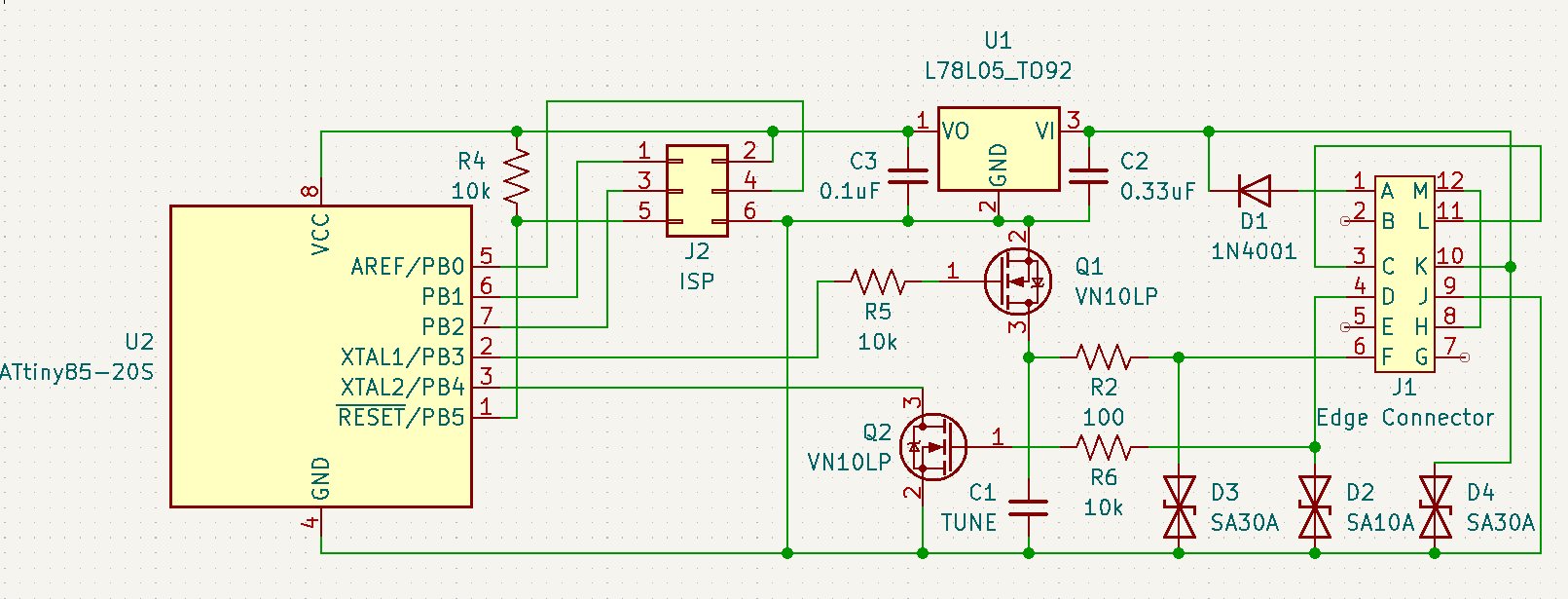
I wasn't going to put in any sort of ESD or even reverse voltage protection at first, as I was intending to just do this once, for myself, probably on protoboard. Since I'm going through the trouble of designing a PCB, I might as well include some level of standard protections. Like most of my electrical knowledge, I had heard of TVS diodes before, but had filed them in the back of my mind poorly. (I completely forgot they existed) So thank you again for the very helpful advice! I added two of them on the input and output signal lines, as well as one on the 12V input rail. I also removed the external 5v pullup in favor of the one built-in on the ATTiny85.
Updated schematic:
| quote | Originally posted by pmbrunelle:
How does this work? It plugs into the unused contacts of the speedo connector?
|
|
It's actually meant to plug into the harness in-place of the old vacuum-servo controller. Spent more time than I care to admit making that card-edge connector footprint.
| quote | Originally posted by pmbrunelle:
Cool, link to the repo here when you're done. PFF is the biggest gateway to Fiero information, so if anyone needs to find that information, they would most likely find it through here.
|
|
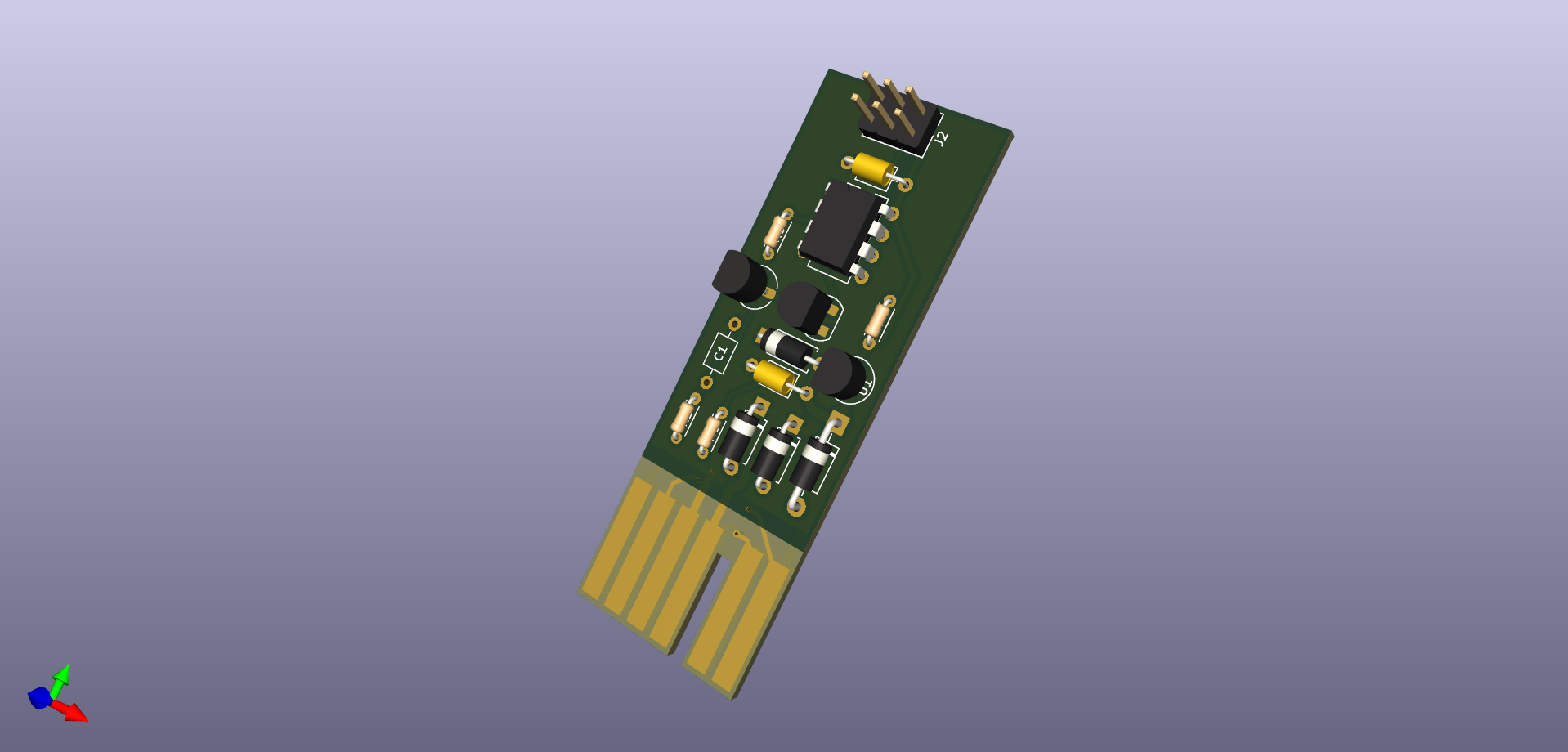
100% intend to! I want to make sure I have a viable and working solution first. Would hate for someone to spend the money on a PCB and components on a half-baked project they found here that won't work for em!
Updated PCB model:
|
|
|
|
pmbrunelle
|
AUG 29, 09:01 AM
|
|
| quote | Originally posted by pmbrunelle:
The gate of Q2 is fragile and is exposed to the outside world. It gets zapped at 20V. An "SA10A" TVS from its gate to ground could protect it. |
|
| quote | Originally posted by TGYK256:
I had heard of TVS diodes before, but had filed them in the back of my mind poorly. (I completely forgot they existed) So thank you again for the very helpful advice! I added two of them on the input and output signal lines, as well as one on the 12V input rail.
|
|
TVS diodes are typically located at the connector pins, but exceptionally for the SA10A of Q2, the TVS needs to be located between the resistor R6 and the MOSFET Q2.
This TVS needs to have a low clamping voltage to protect the MOSFET gate, but if you put it directly at the connector, it may conduct with 12V seen in normal operation. So, the TVS in this case should be "hidden" behind the resistor, so that it doesn't influence the stock ECM too much.
| quote | Originally posted by TGYK256:
I also removed the external 5v pullup in favor of the one built-in on the ATTiny85.
|
|
The internal pullup resistor of a microcontroller typically has a higher resistance than something you could put externally, so there could be less noise immunity especially with longer wires. That said, the internal pullup should work for your use case, with Q2 located nearby on the same PCB.
|
|
|
|
TGYK256
|
AUG 29, 03:07 PM
|
|
| quote | Originally posted by pmbrunelle:
TVS diodes are typically located at the connector pins, but exceptionally for the SA10A of Q2, the TVS needs to be located between the resistor R6 and the MOSFET Q2.
This TVS needs to have a low clamping voltage to protect the MOSFET gate, but if you put it directly at the connector, it may conduct with 12V seen in normal operation. So, the TVS in this case should be "hidden" behind the resistor, so that it doesn't influence the stock ECM too much.
|
|
I might be wrong here, but instead of moving the TVS connection point behind the resistor, I've been looking into more fitting N-channel TO-92-3 FETs. My reasoning behind this is that the resistor will limit the shunting current ability of the TVS in an overvoltage situation, according to ohm's law. Also, I believe the TVS would be continually cycling during normal operation.. At a minuscule current behind the resistor, but still passing current nonetheless with a 10V reverse standoff voltage.
I believe that the 2N7000 would be fitting, bringing the VGS max up to 30V, and allowing the use of an SA16A TVS (max clamping of 26V) instead of an SA10A, which would bring the reverse standoff up to 16V, keeping it from operating during nominal vehicle running conditions. Thoughts?
| quote | Originally posted by pmbrunelle:
The internal pullup resistor of a microcontroller typically has a higher resistance than something you could put externally, so there could be less noise immunity especially with longer wires. That said, the internal pullup should work for your use case, with Q2 located nearby on the same PCB. |
|
For a bit of context, the current trace length for the input FET is < 10mm. I'm unsure if that would be long enough to be influenced by noise, and it has a full groundplane coverage from the other side of the board. I know that the automotive environment is pretty noisy, but I don't have really any knowledge to base onboard noise reduction off of.[This message has been edited by TGYK256 (edited 08-29-2025).]
|
|
|
|
TGYK256
|
AUG 31, 06:33 PM
|
|
Update: I had to change the schematic slightly to make use of the Timer/counter 0 output, as well as the INT0 input. I believe I have what should be a functional product at this point, but have done no debugging yet. Going to be "Proofreading" and double-checking everything before ordering a small batch of boards and at least 1x BOM for testing. Although I can't guarantee that this works at all, I have pushed my KiCAD project as well as my Platformio-based code to github. The repo can be found here.
Thank you again to everyone who has reached out to help in one way or another! I am unsure if I should keep bumping this thread with new updates or start a new one - Any mods that can weigh in on this?
|
|
|
|
Spadesluck
|
SEP 01, 09:39 AM
|
|
|
Keep bumping it, some of us like to see projects through.
|
|
|
|
pmbrunelle
|
SEP 01, 09:42 AM
|
|
Your idea of the 2N7000 and high TVS voltage is good.
It is good that you verified what microcontroller peripherals/timers are available on which pins. Some folks at my work don’t check this adequately before making a PCB!
PFF doesn’t have much in the way of moderation, so you could make a new about your project, but leave links to both threads so the information can be found regardless of the entry point.
|
|
|
|