 
     |
| Riviera digital Instrument cluster (IC) into a Fiero dash (Page 3/14) |

|
rbell2915
|
SEP 02, 09:27 PM
|
|
Hey Cajun, nice work so far. I did something similar except I swapped in a 4th gen firebird cluster. I wanted my interior to look like a prototype Fiero. I needed to trim a lot of the upper surround in order to see the gauges. I still need to remove everything again and trim it even more this winter. Then I had it wrapped in vinyl (which is coming loose so I need to take it somewhere when it's done.) Here are the links. Might be helpful. I also have a build thread. PM me if you need anything.
YouTube demo.
Build thread.
|
|
|
|
Chris Eddy
|
SEP 02, 09:46 PM
|
|
Cajun, if you think that the minifit are not the right size, have a look at the Amp (TE) Universal Mate N Lock. They can handle larger gauge wire.
Glad to see you are recovering well!
|
|
|
|
Cajun
|
SEP 06, 01:48 PM
|
|
I just ran across an achieve post by Darth Fiero dealing with the same devior. Unfortunately it appears he gave up on the project. The list was dated 2004.
I'm wondering if Darth Fiero and or Stinkin_v8 are still around and active here?
I'm looking for a little assistance. In that 2004 post information about in referencing files from diy-efi; ALDLStuff.zip, files A146.DS & A180.DS. Apparently the files are able data stream information from the Riviera BCM!
Thank you in advance.
|
|
|
|
Cajun
|
SEP 13, 02:02 PM
|
|
I have done a little more work on this project. A pause due hurricanes, heat and honey-dos.
I have been in the process of installing wire markers {labels) on all the wiring. I did not want to leave anything to chance as there a bunch of wires from multiple connectors to deal with. Initially I had installed tape on type wire markers but found that after a while they begin to peel off, rub off, etc. In some cases I have placed clear shrink wrap over some of the wire markers where it made since. On other connectors, i.e. the BCM connector I have installed plastic wire markers. Oh, I am waiting for additional plastic wire markers to arrive.
In the mean time i have tore down my test jig setup as I needed some of the parts to complete the install.
I have prepped the connector and wiring for the Riviera digital IC.
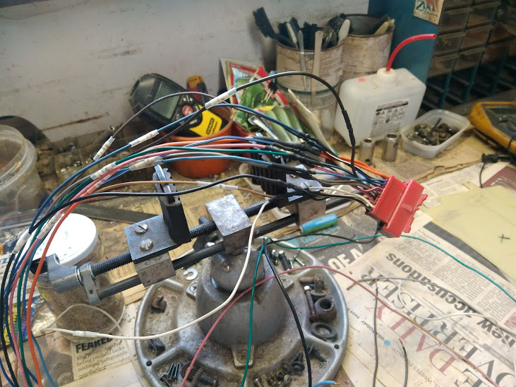

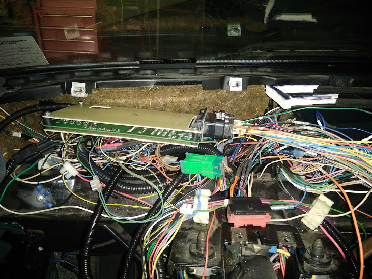
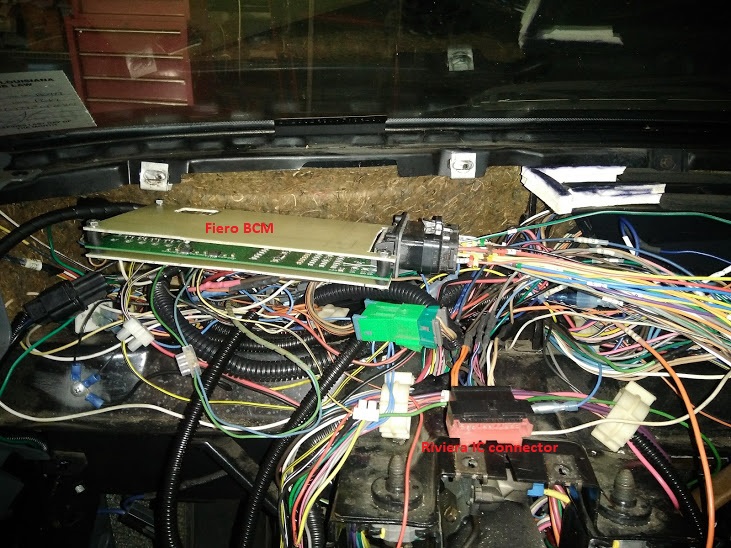
I have installed some protectors over the Fiero BCM. Did not want to anything shorting a component out once it was placed under the dash board. The first photo is of the Fiero BCM without the protectors installed.
BCM with protector installed:
BCM with protector installed side view:
BCM connector and wiring. On this wiring harness I need to complete the install of the plastic wire markers.

I have reconfigured my wiring road map. I think this approach will workout much better than my initial wiring configuration.
My proposed placement of the BCM is directly under the driver side speaker. I have checked to see if the BCM could be serviced from this location. It appears to work doing a test fit?
A couple of set backs:
1. the smoked Lexan has not yet arrived. It was supposed to have arrived Friday but when I checked it was "marked" as back ordered.
2. Another hurricane is scheduled to make landfall Tuesday which means I now have to pickup everything and prepare for a storm again!
If I get a little free time I will begin wiring the various connectors. Hope to shoot a couple of photos with the connectors in placed wired up.
We are getting close...............
|
|
|
|
Chris Eddy
|
SEP 13, 02:28 PM
|
|
Awesome, that all looks great.
Meanwhile, since you are doing all of that, I have been working on the software for reading the serial stream from the ECM and the OBDII code read port software.
This will take some time to work out all of the details and test, but while you are doing wiring et all, I can beaver away at that. Those features are not necessarily even needed in your case.
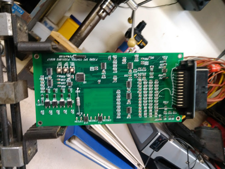
The PC board would not easily get smaller, as it is already surface mount, but I could re-arrange it to fit in an enclosure. The only issue there is that any enclosure would certainly be larger than the board and harder to tuck away.
Maybe a board that fits piggy back on the back of the Riviera IP? Is there any clearance there?
We are all pulling for you to pull through the next hurricane. You must be getting pretty good at it!
|
|
|
|
Cajun
|
SEP 13, 04:27 PM
|
|
Chris,
There is insufficient room to place the BCM behind the Riviera IC. I have already attempted that fit. Also, I'm thinking that the Riviera digital IC may be more sensitive to heat?
Did you receive my email with the ALDLStuff.zip? If so, did the files make any sense?[This message has been edited by Cajun (edited 09-13-2020).]
|
|
|
|
Cajun
|
SEP 13, 04:33 PM
|
|
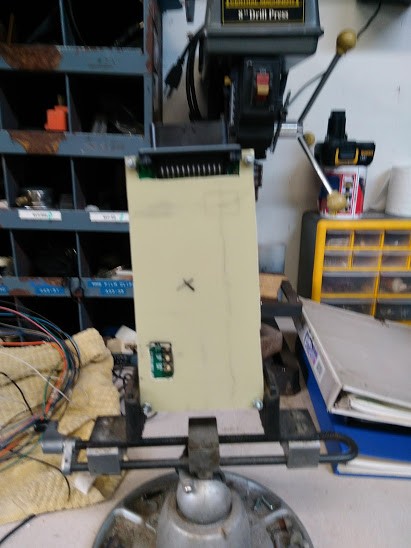
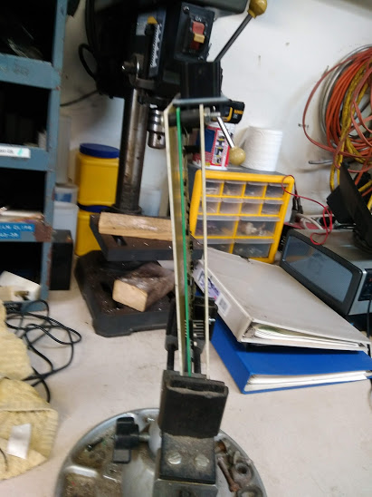
While I was messing around with the connectors and wiring I figured I would do a test fit of the connectors in the dash location. It appears that I will have room to place the BCM in that location and have the ability to remove or service it if needed.
I know, it's pretty messy...............
 [This message has been edited by Cajun (edited 09-13-2020).]
|
|
|
|
Cajun
|
SEP 16, 04:03 PM
|
|
A little more progress today. I know progress has been a bit slow, but hey I'm dealing with some 65 plus wires and I don't want to make any mistakes or at least too many mistakes in the wiring interface changes. I would hate to have to remove the dash a second or third time to troubleshoot wiring errors.
Anyway, I have cut our the OEM Fiero instrument cluster (IC) connectors C1 & C2 and prepped the wires for the interface connections. That's the next step!
.jpg)
.jpg)
My next step will be to connect the Riviera IC connector to the Fiero C3 interface terminal strip (connector).
The faceplate Lexan still have not arrived. If it arrives after I get all the interface wiring sorted out I plan to just go ahead and install the Fiero surround & Riviera IC. A faceplate template has been cut and test fit. Hopefully I'm good to go on that end?
|
|
|
|
Cajun
|
SEP 21, 02:33 PM
|
|
Since it's raining out and waiting on what Tropical Storm Beta is gonna do figured I would do a little more wiring work. I have now completed wiring in the Riviera digital IC connector into my GT. Guess that was the easy part? Next comes wiring in the Fiero BCM and of it's associated wiring.
The real fun part at least for me was making the wiring changes to Fiero wire #44 at the remote diming transistor. Nice there is a connector at the transistor. But crawling under the dash area to wire in connectors is a PIA affair!
I have made a few changes to my wiring road map. I will include those photos also.
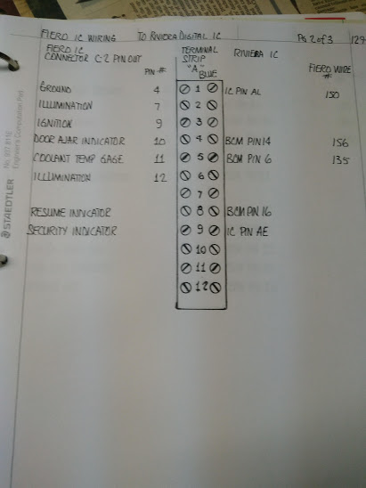
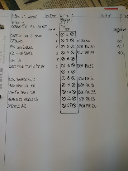
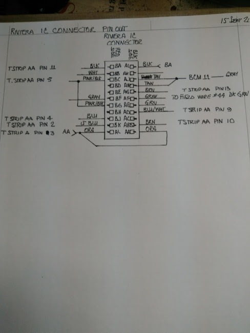
Here is a photo of my wiring road map for the Riviera digital IC connector:
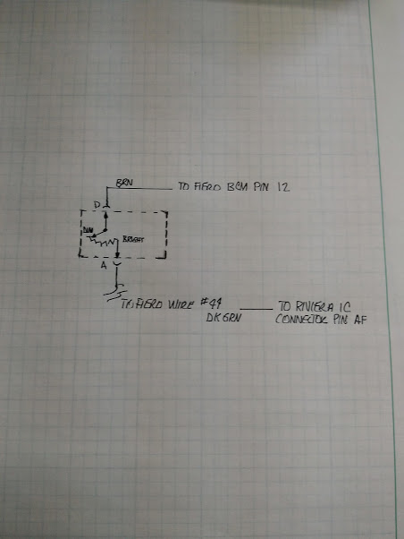
Wiring diagram for the changes to the interior lighting control:
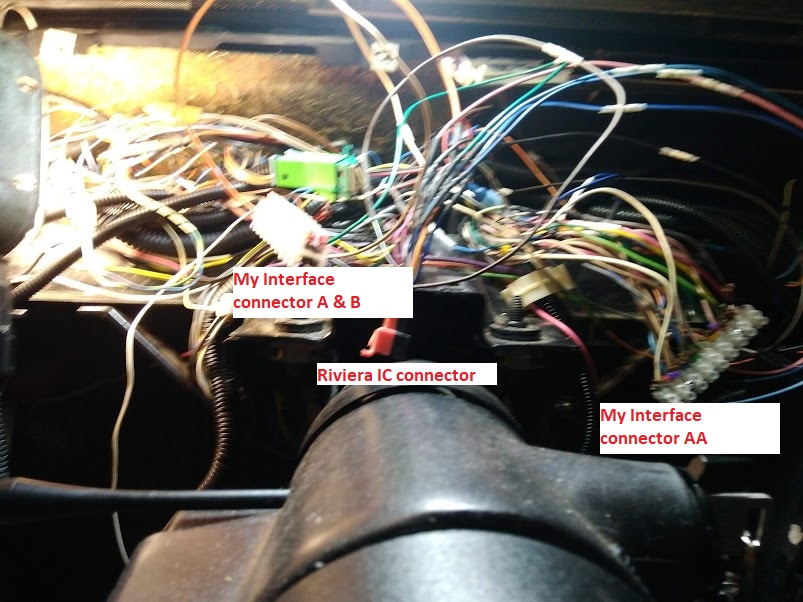
The Riviera IC connector wired into my GT:
|
|
|
|
Chris Eddy
|
SEP 21, 07:36 PM
|
|
Just FYI on the dimmer.. it was a real PITA.
The dimmer module is a transistor set up as an "emitter follower". It amplifies the current through the dimmer pot to a current about 50 times the dimmer pot, enough to drive a fistful of lamps.
But the Riviera IC has it's own built in PWM dimming output.. and the command to the IC comes through the serial communications with the rest of the gauge signals.
So the dimmer command must come from the BCM board. And therefore the dimmer pot must go into the BCM board.
There are many analog inputs on the BCM board that are current sources.. the ideal way to measure a resistor, such as the fuel gauge or the temp sensor. So a similar circuit drives the dimmer pot.. a current is sourced, and the voltage across it is measured. V=I*R.
On top of that, the current source circuits all want to drive a resistor that is connected to ground. The original dimmer wiring has one wire from the pot wired to +12. Again, backwards. So wiring has to be changed to ground.
All of that leads up to the reason why the dimmer module is removed.. because it is wired completely different than how we need it to be.
|
|
|
