
 
     |
| ECM questions, sensors, TPS and MAP (Page 3/5) |

|
fierobear
|
FEB 25, 05:00 PM
|
|
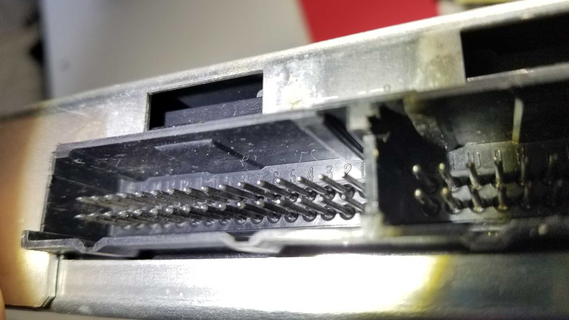
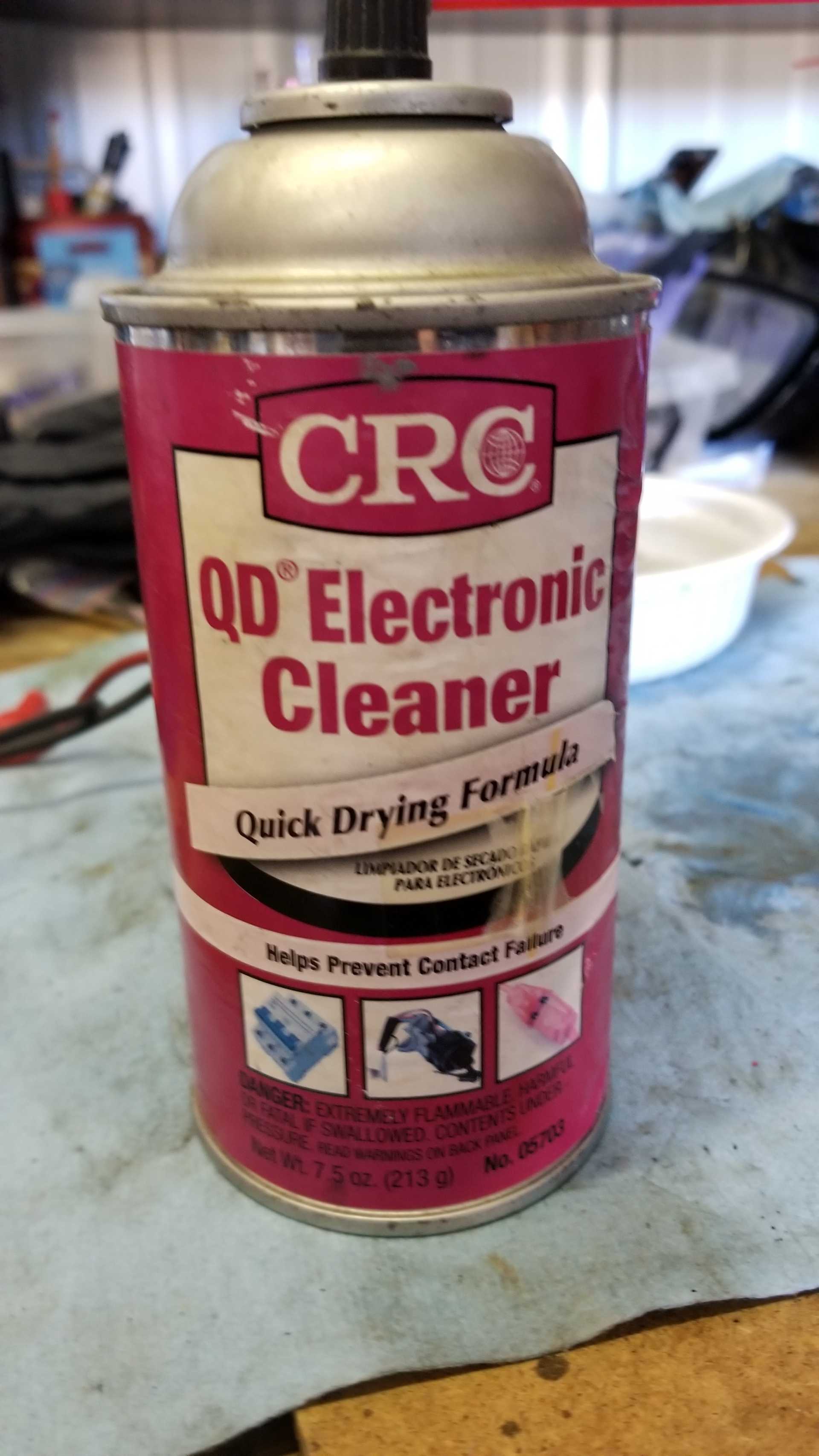
Looking at the pins on the ECM, there seems to be some slight build up of corrosion. I used some of the connector cleaner in pic 2, and a plastic bristle brush, but it doesn't seem to be doing the job. Any suggestions on a better cleaning method?
One thing I need to point out, is that this was a sudden change in the car's performance. I'd been driving this car for at least a year and a half after restoration, without even a hiccup. I drove cross town about 10 minutes, at 55-60mph, stopped for 10-15 minutes, and when I started the engine it was immediately running like s*** and has ever since. This suggests to me that corrosion on pins or wires wouldn't cause a sudden and ongoing issue like this.
|
|
|
|
Raydar
|
FEB 25, 05:13 PM
|
|
| quote | Originally posted by fierobear:
...
This suggests to me that corrosion on pins or wires wouldn't cause a sudden and ongoing issue like this.
|
|
I would tend to agree. The pictures of the sensor connectors that you posted earlier...
Those really don't look too bad. I have seen way uglier wires that worked just fine, although that really doesn't mean anything.
I might try to check that gray wire that supplies the 5 volts. The best way to do it is if you can get a meter probe into the connector, alongside the wire, to make the measurements.
Maybe tug on the wires and pins carefully, to make sure nothing is broken inside the plastic connector shell.
Maybe it got pinched, or burned, somewhere along the way. I forget how it's routed, but if has to be one of the longer wires in the harness. (This, of course, is a complete crap-shoot, but nothing else is making much sense, either.)
Edit - Wait... Unless there are two gray wires crimped into the connector at the ECM, that 5 V wire splits off in two different directions, somewhere in the harness, to feed two sensors that are on opposite ends of the plenum. There has to be a solder joint or a crimp somewhere. That would be a place to look. Of course, it's gonna be a lot of fun chasing it through the harness.[This message has been edited by Raydar (edited 02-25-2020).]
|
|
|
|
theogre
|
FEB 25, 07:07 PM
|
|
You almost always have Splices in the harness because GM and most others only crimp 1 wire in 1 end for 90+% of times because most Terminals and their Shells only accept 1 wire.
Examples:
 | | CLICK FOR FULL SIZE |
and see http://www.fiero.nl/forum/F...HTML/143417.html#p21
Read my post above... All 3 wire ECM sensors have 5v and Ground from ECM. Either/both are iffy then 1 or more sensors will have problems.
Two wires sensor like engine coolant temp are part of "voltage divider" etc in the ECM and 1 wire here is mostly grounds.
Splices rarely die but if "water" gets into the harness will eat the copper right near them.
Water will wick thru any weak weak spot and eat the copper faster then the solder section.
Might test the wire w/ Ω meter but:
1. Disconnect the wire from ECM and any sensors.
2. May don't help unless wire is really bad.
3. Really need an analog meter or Digital w/ Rel button to Zero out the probes. More so if you run long probe wires to test w/o pulling ECM plug thru the firewall.[This message has been edited by theogre (edited 02-25-2020).]
|
|
|
|
pmbrunelle
|
FEB 25, 07:17 PM
|
|
I'd de-pin the TPS and MAP connectors to have a look at the terminals. De-pinning is a fully reversible operation; when you're done looking, you can put things back as they were.
You can use a Weather-Pack depinning tool such as Aptiv 12014012.
It's available at https://www.mouser.com/
With the terminals removed from the plastic connector shell, you can:
-Look at the terminals
-Plug them into the sensors and start the car, allowing for easy probing while the car is running.
-Wirebrush the terminals clean
-Crimp new replacement terminals onto the original wires
-Change the old crusty plastic connector shell.
If you want to buy individual parts (terminals, shells, etc), I have the Aptiv (ex-Delphi) part numbers available if you're interested. A complete pigtail is an option, but it has the disadvantages of introducing new splices into the harness (new points of failure), the harness becomes lumpy, and you'll probably have to mess with the stock wire loom.
The ECM pins don't look too bad, but that's my uninformed opinion... essentially hogwash.
I took a crash course (a few days long, so just enough to get a glance on the subject) on electrical contacts, and our teacher showed up graphs of contact resistance barely changing for a long time, and then all of a sudden shooting up. So I wouldn't discount connector corrosion as the cause of your problems because they appeared all of a sudden.
| quote | Originally posted by Raydar:
Edit - Wait... Unless there are two gray wires crimped into the connector at the ECM, that 5 V wire splits off in two different directions, somewhere in the harness, to feed two sensors that are on opposite ends of the plenum. There has to be a solder joint or a crimp somewhere. That would be a place to look. Of course, it's gonna be a lot of fun chasing it through the harness.
|
|
It's a crimp splice (S511) with tape over it, and IIRC it's in the main fat wire bundle near the location of the oil pressure sending unit.
There are also splices connecting the signal grounds together (MAP/MAT together, and CTS/TPS together).
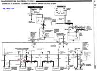
Edit: see wiring diagram in FieroJimmy's first post in this thread.[This message has been edited by pmbrunelle (edited 02-25-2020).]
|
|
|
|
Raydar
|
FEB 25, 07:22 PM
|
|
| quote | Originally posted by theogre:
Splices rarely die but if "water" gets into the harness will eat the copper right near them.
Water will wick thru any weak weak spot and eat the copper faster then the solder section.
|
|
I was thinking more along the lines of a mechanical failure, or a heat or abrasion related failure. (Burned or "chafed" wire. Maybe a high resistance short to ground, like the edge of a shield or something.)
But I hadn't even considered moisture. That's a good idea.[This message has been edited by Raydar (edited 02-25-2020).]
|
|
|
|
theogre
|
FEB 25, 07:31 PM
|
|
Even w/ weather pack pin tool... ears can get pushed in and may not hold.
Can Carefully pry out the ears a little so will hold again.
Can get Weather pack tools at amazon and more likely faster and free shipping then Mouser.
Might get ends to but many are cheap copies so be careful w/ them.
Note: Tools and ends may not fit right because of tolerance problems so don't force them. Worse is ends have damage from people beating the hell out of them.
Is likely not the problem here but checking them won't hurt.
|
|
|
|
theogre
|
FEB 25, 07:49 PM
|
|
| quote | Originally posted by Raydar:
I was thinking more along the lines of a mechanical failure, or a heat or abrasion related failure. (Burned or "chafed" wire. Maybe a high resistance short to ground, like the edge of a shield or something.)
But I hadn't even considered moisture. That's a good idea. |
|
Splices rarely die for mechanical problems too. Even new copper will break near the splice before the joint fails nearly every time. Is like wood etc often fails before proper glue joint fails.
Plus GM uses a lot of tape on the splices to avoid cutting other wires etc. "Water" oil etc can loosen or wreck the adhesive and will still try to do the job.
Now if you have exhaust leak(s), too close to exhaust, something pinch/pull harness, etc... Can cause this and Far Worse depending just what circuits have melted/worn insulation.
Example: Bad motor/trans mounts can yank the harness and hoses.[This message has been edited by theogre (edited 02-25-2020).]
|
|
|
|
fierobear
|
MAR 12, 02:56 PM
|
|
It is unlikely that water is the culprit in this situation because:
1. The day of the sudden failure was dry, no rain.
2. Since I completed the restoration of this car, it stays indoors all the time. I don't drive it in the rain or even park it outside over night, so no dew on it.
3. I don't wash the car with water/soap since the restoration/repaint. I only use detailing sprays and dri-wash polymer.
Updates:
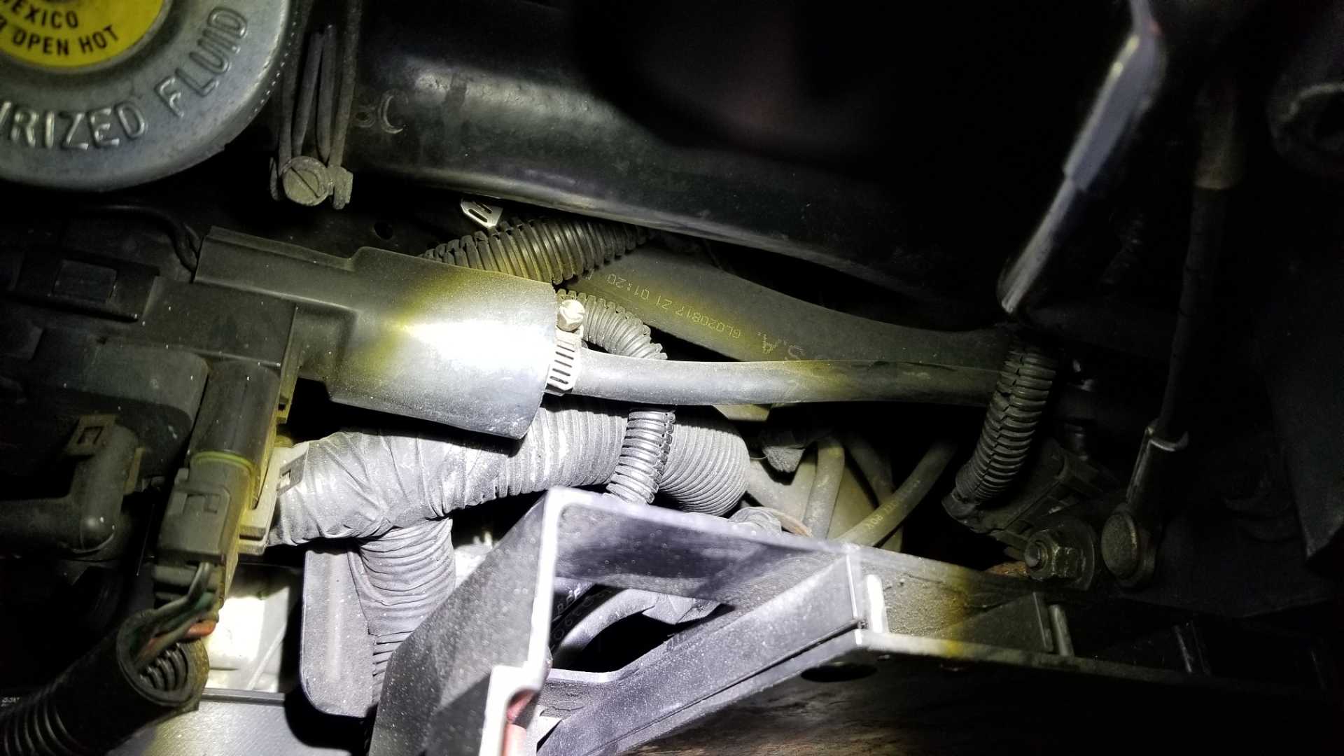
I have a spare V6 engine wiring harness that was in a box. I was able to located the splice we were talking about, circled below:
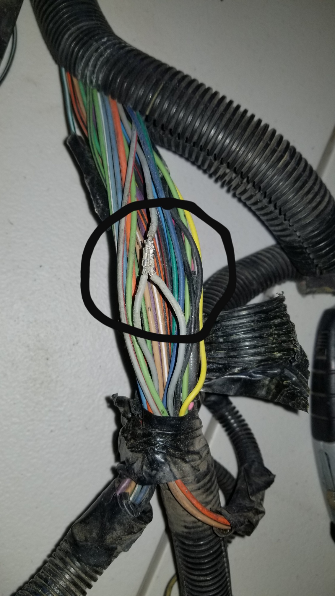
Based on examination of the location on the spare harness, I figure that the splice is located below and to the right of the EGR Solenoid:
It's going to be a ***** to get to, but before I start tearing things apart, there is something else I discovered. Just for the hell of it, I decided to move the metal arm on the TPS with my hand while the engine was running and my scanner was hooked up. Recall that I'd never seen anywhere close to 5v on the scanner from the TPS during normal operation. Not even on cars that aren't throwing a code or running badly. When moving the TPS arm all the way through it's travel range, The voltage when up to 5v! This is with the sensor connected, of course. So I'm wondering if we are actually getting full and proper travel out of the TPS metal arm by the throttle pushing it? Is it possible that something has gotten out of adjustment or worn out (like the spring on the throttle assembly) over time such that we aren't getting proper travel range on the TPS? This might not explain the sudden rough running, unless something mechanically broke.
Another test I did was to swap ECMs from the red Forumla, which is running well, to the GT. No change in any readings or running. I think we can rule out an ECM problem, and with my manual test of the TPS arm, it seems unlikely that the wiring is bad.
|
|
|
|
Raydar
|
MAR 13, 07:07 PM
|
|
It really sounds like you are on to... something.
The fact that you can get the full 5V from the TPS circuit is significant.
|
|

|
theogre
|
MAR 13, 11:29 PM
|
|
When installed in a car... TPS often never reaches 5v by turning throttle to WOT on TB/TBI by hand or by pedal. Close to same reason doesn't see 0v @ idle.
Go by angle/% of throttle reported by a scan tool.
Turn throttle by hand should see 99-100% @ WOT even when not seeing 5V on the scanner or on meter on sensor.
But Press the pedal to floor often can't reach WOT because pedal and/or cable problems and more so for Fiero w/ 3-5 times cable length then front engines.
See my Cave, Throttle Cable
|
|
|
|