
 
     |
| 85 Notchie Build (Page 22/23) |

|
zkhennings
|
FEB 13, 12:14 PM
|
|
Been working on the wiring, it has been a lot of research and making diagrams to keep everything straight.
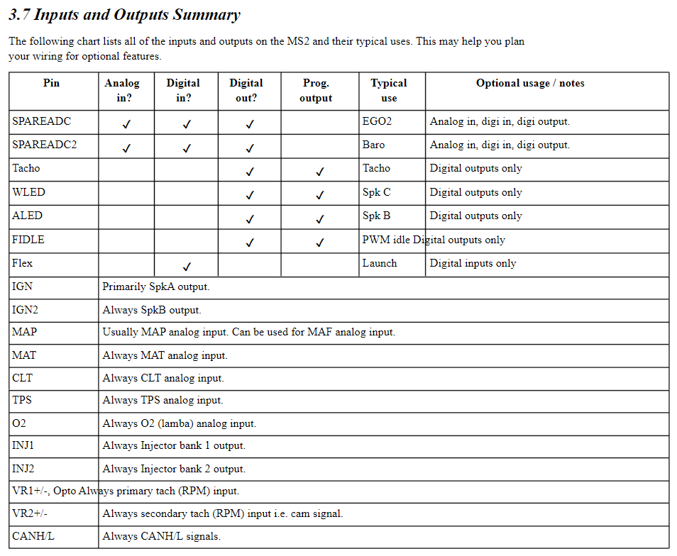
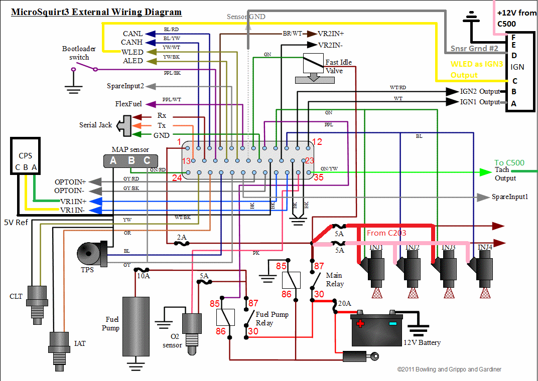
First, some Microsquirt info on how things are wired and can be wired.
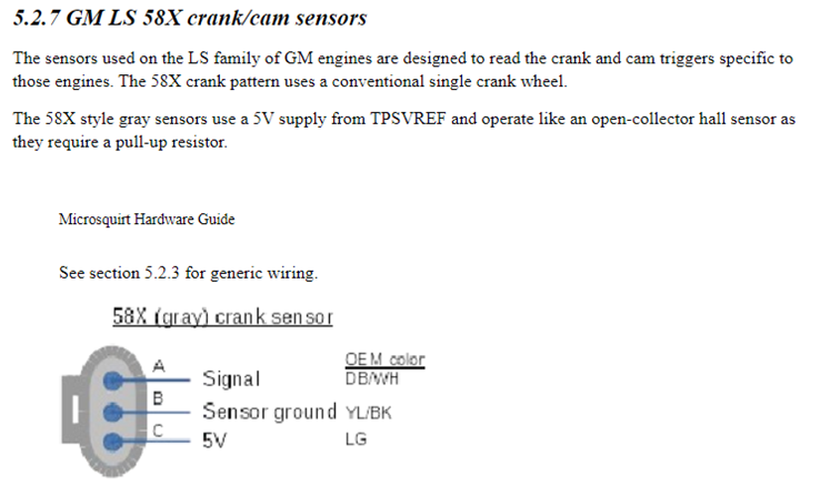
Wiring the Crank Position Sensor (CPS)
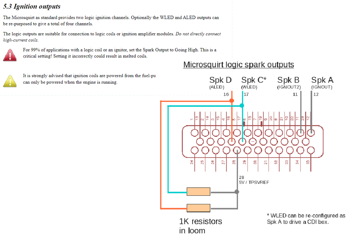
Wiring the ignition. I will be using WLED output with the 1K resistor to 5VREF to power the 3rd ignition channel needed for the DIS.
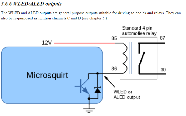
And I will be using the ALED output to run the fan
And triggering the fuel pump relay with the Fuel Pump trigger wire from the Microsquirt. The Microsquirt turns the relays on with ground, so I will be wiring them that way.
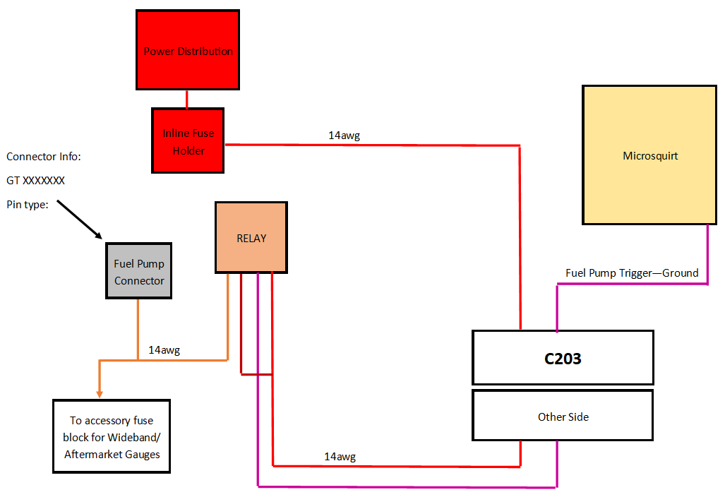
I am going to run a dedicated hot wire from the power junction through the C203 using a non-populated spot and have that go to a relay located next to the ECU to turn power on to the pump and some accessory gauges. There will be a small fuse block with a few spots to run these things next to the relay.
Here is the C203,this diagram has wire gauges and the pins needed to rewire it :
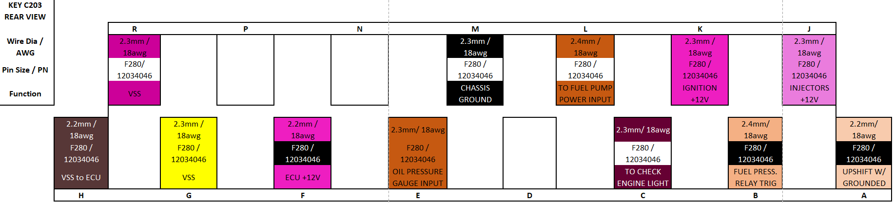
I will be using pins J and K to send power to the fuel injectors, and there are two injector trigger wires coming out of the Microsquirt to ground the injectors for batch firing the two banks. Since the firing order is 1 2 3 4 5 6, it already alternates banks every time it fires, so I will wire the two banks on different triggers.
Pin F will power the Microsquirt, Pin E will receive input from the oil pressure sensor, it is a 0-90ohm sensor so it should still work with the gauge. I will also have the line spliced to go to an input on the Microsquirt so that I can log oil pressure.
Here is the C500, this diagram has wire gauges and the pins needed to rewire it:
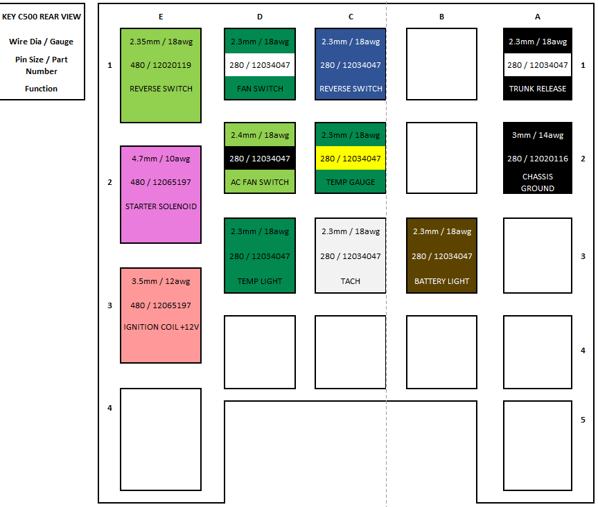
Pin E3 will provide power to the ignition coil, D1 will be tied to the ALED output from the Micosquirt to trigger the fan, C2 will go to an output from the temp sensor, I will use this coolant temp sensor which is 3 pin to be able to send coolant temp signal to the Microsquirt as well as the temp gauge. PN: 10096181
C3 will be tied to the Tach output wire from the Microsquirt to run the tach, and B3 is the battery light wire that will go to the alternator.
Here is an overall wiring diagram of how it will look.
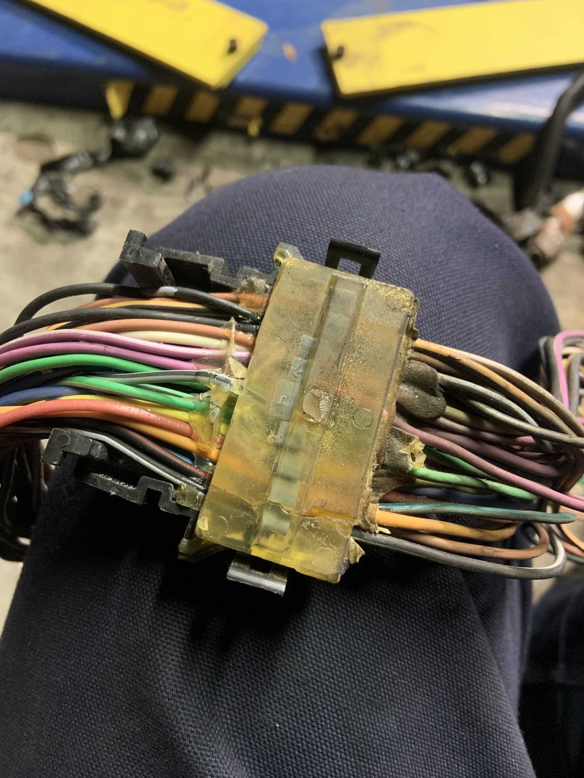
I removed all the insulation from my original 4cyl wiring harness. I was able to figure out why back in 2010 I started getting an intermittent power issue to ECU, I solved it at the time by running new power wires to the ECU.
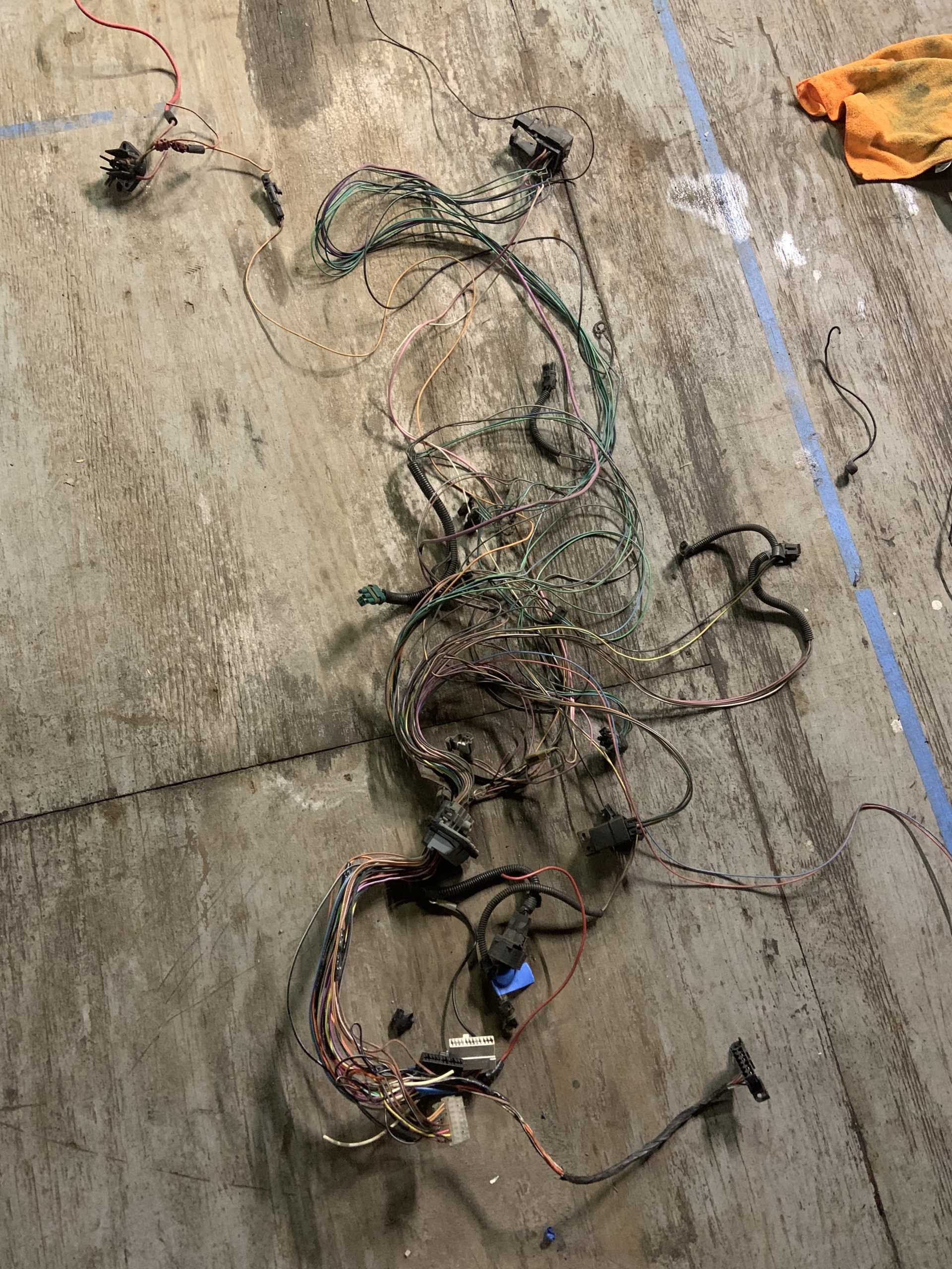
I boiled the bulkhead pass through using Fieroguru's instructions, worked great.
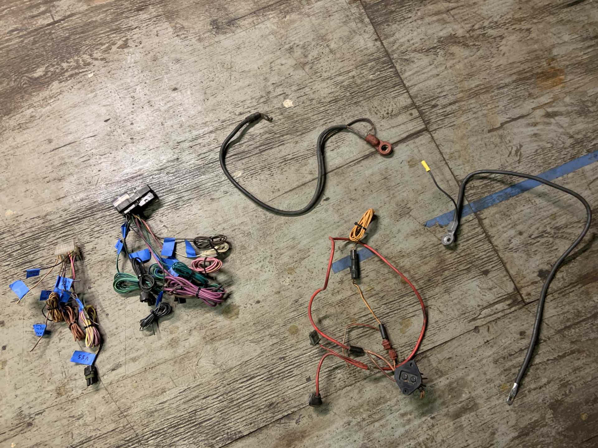
After figuring out what I was doing and making all my diagrams, I paired the harness down to the connectors I need, and trimmed any wires I will be replacing and labelled them to make it easier to see where everything was.
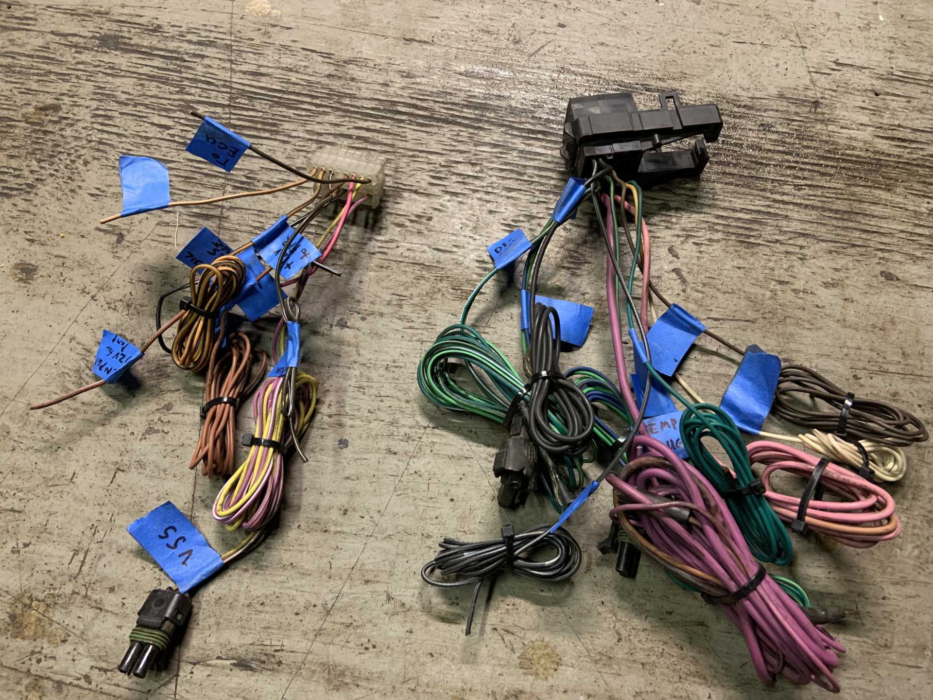
Here's the wiring I am using:
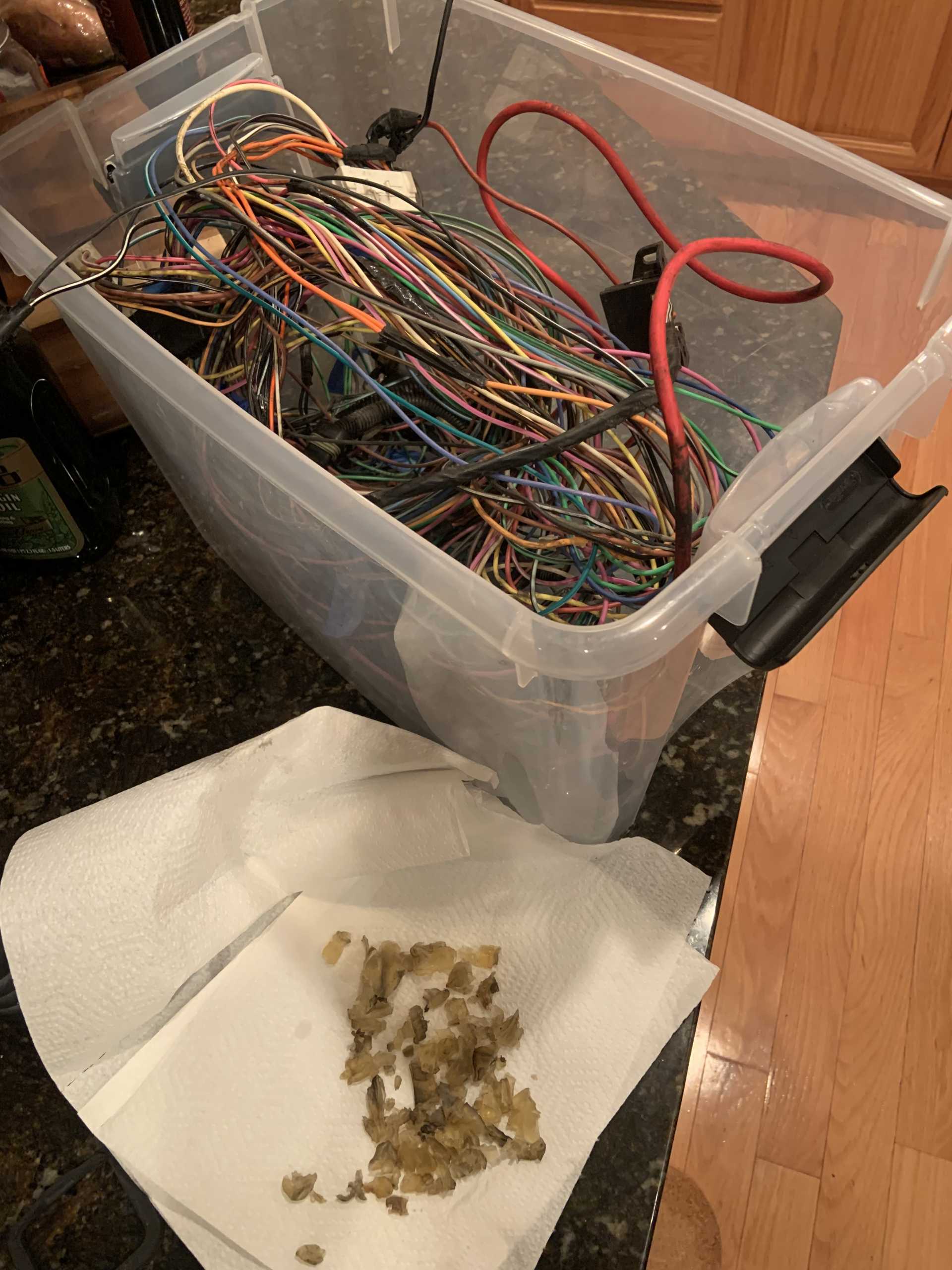
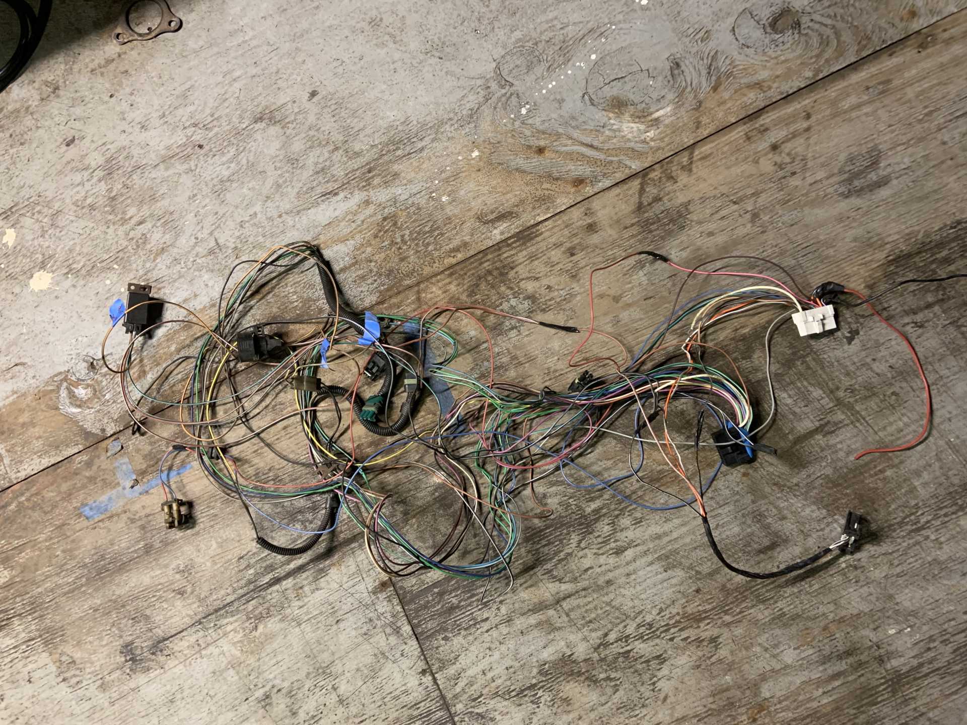
And the wiring I am not (though I will reuse the fuel pump relay)
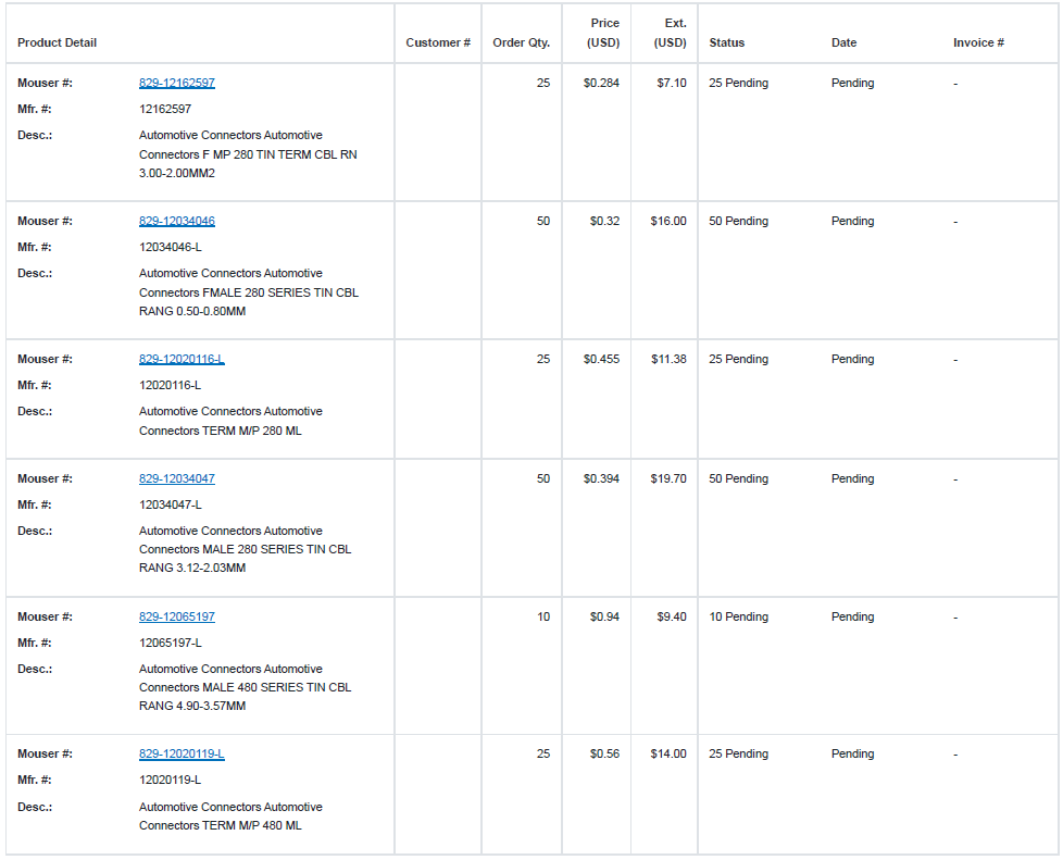
I ordered new pins for C500 and C203, here is a list of all the possibilities:
C203 PINS
12-14awg: 12162597
https://www.mouser.com/Prod...7jpqap4wGEtxsg%3D%3D
18-20awg: 12034046
https://www.mouser.com/Prod...1xzQG8c%2FZrwg%3D%3D
C500 PINS
150 Series:
17-20awg: 15344866
https://www.mouser.com/Prod...Obt1XEOt6rAAOA%3D%3D
280 Series
10-12awg: 12084586
https://www.mouser.com/Prod...FL2p3rKY3shgCg%3D%3D
14-16awg: 12020116
https://www.mouser.com/Prod...FL3bGErK9Bv5ow%3D%3D
18-20awg: 12034047
https://www.mouser.com/Prod...FL0P6hZQKNlzpg%3D%3D
480 Series
12awg: 12065197
https://www.mouser.com/Prod...dyd%252BacawLA%3D%3D
14-17awg: 12065196
https://www.mouser.com/Prod...5AK9w5s05garzJQOAAFT
18-20awg: 12020119
https://www.mouser.com/Prod...t2KKItj3GKFjBA%3D%3D
And here is what I actually ordered:
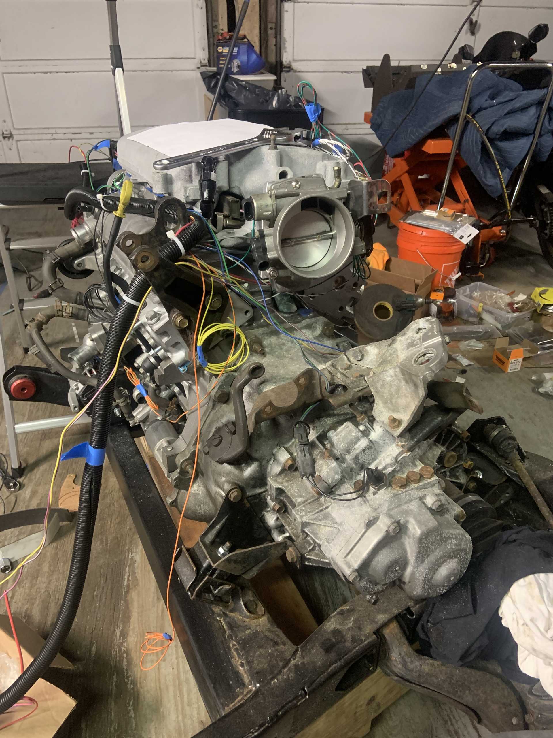
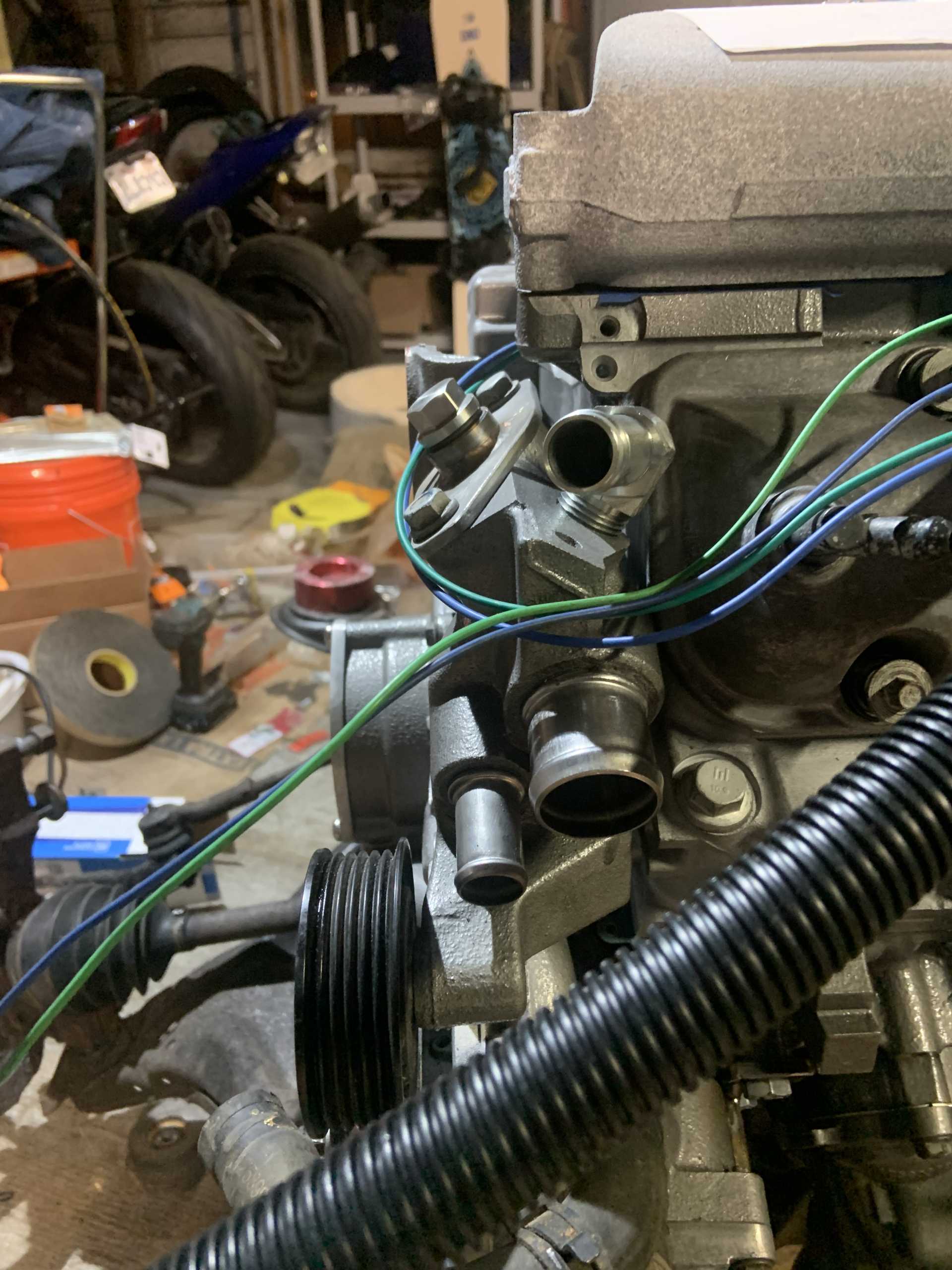
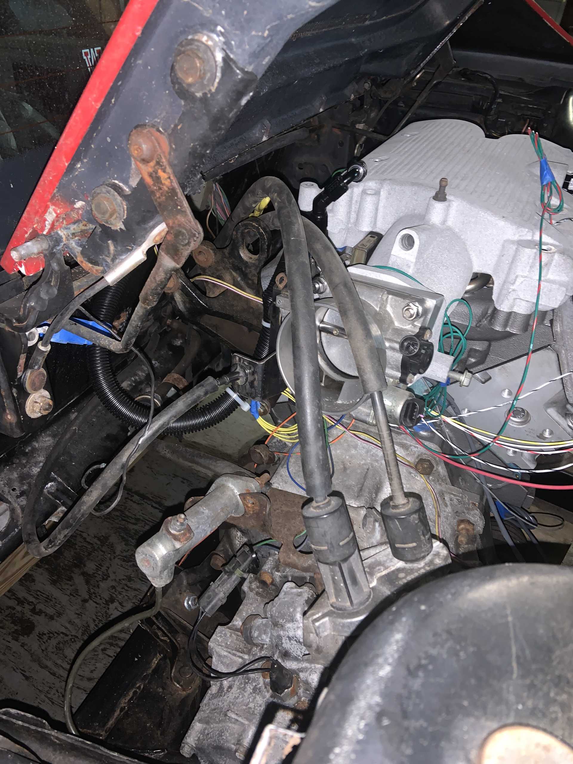
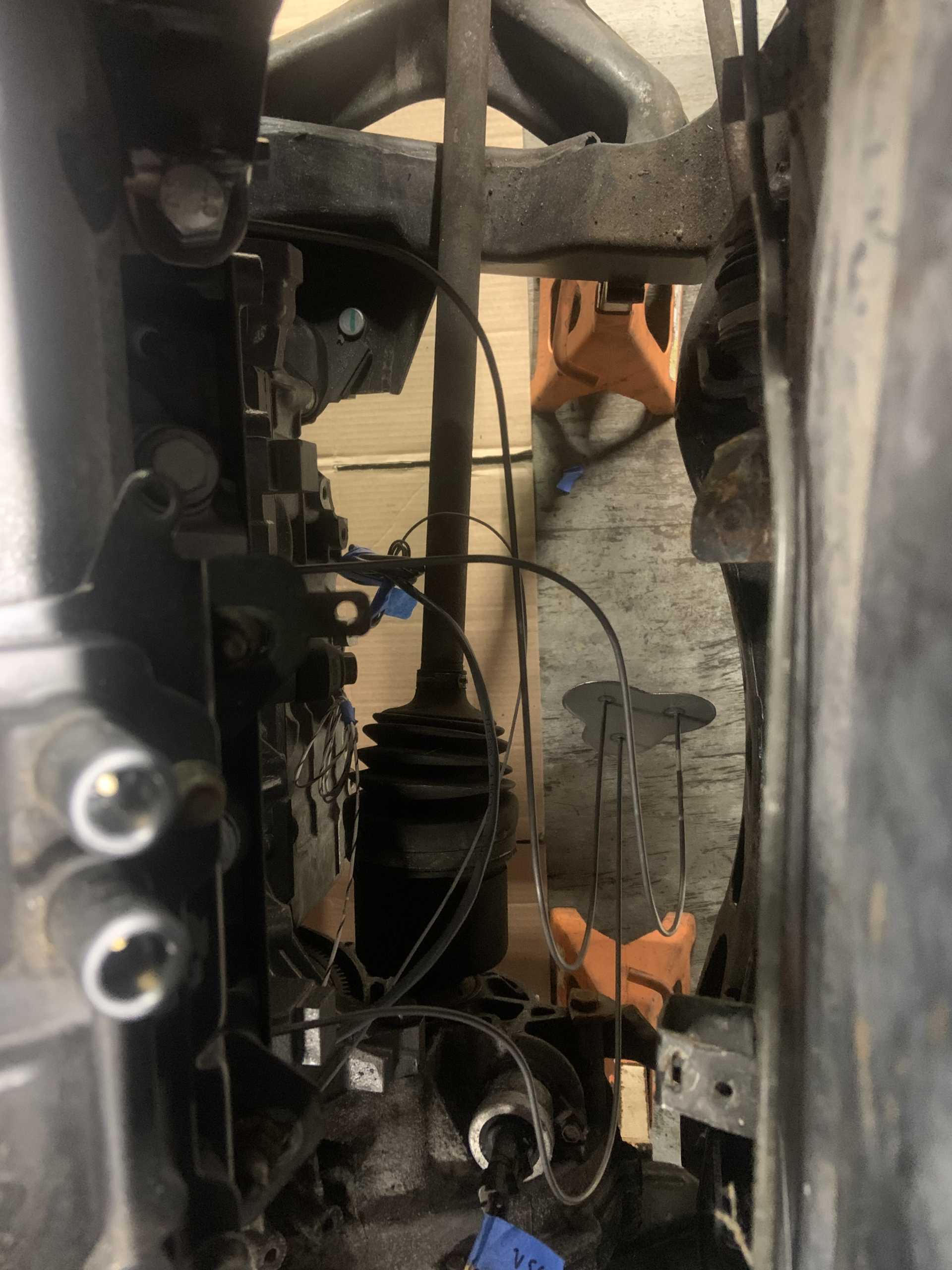
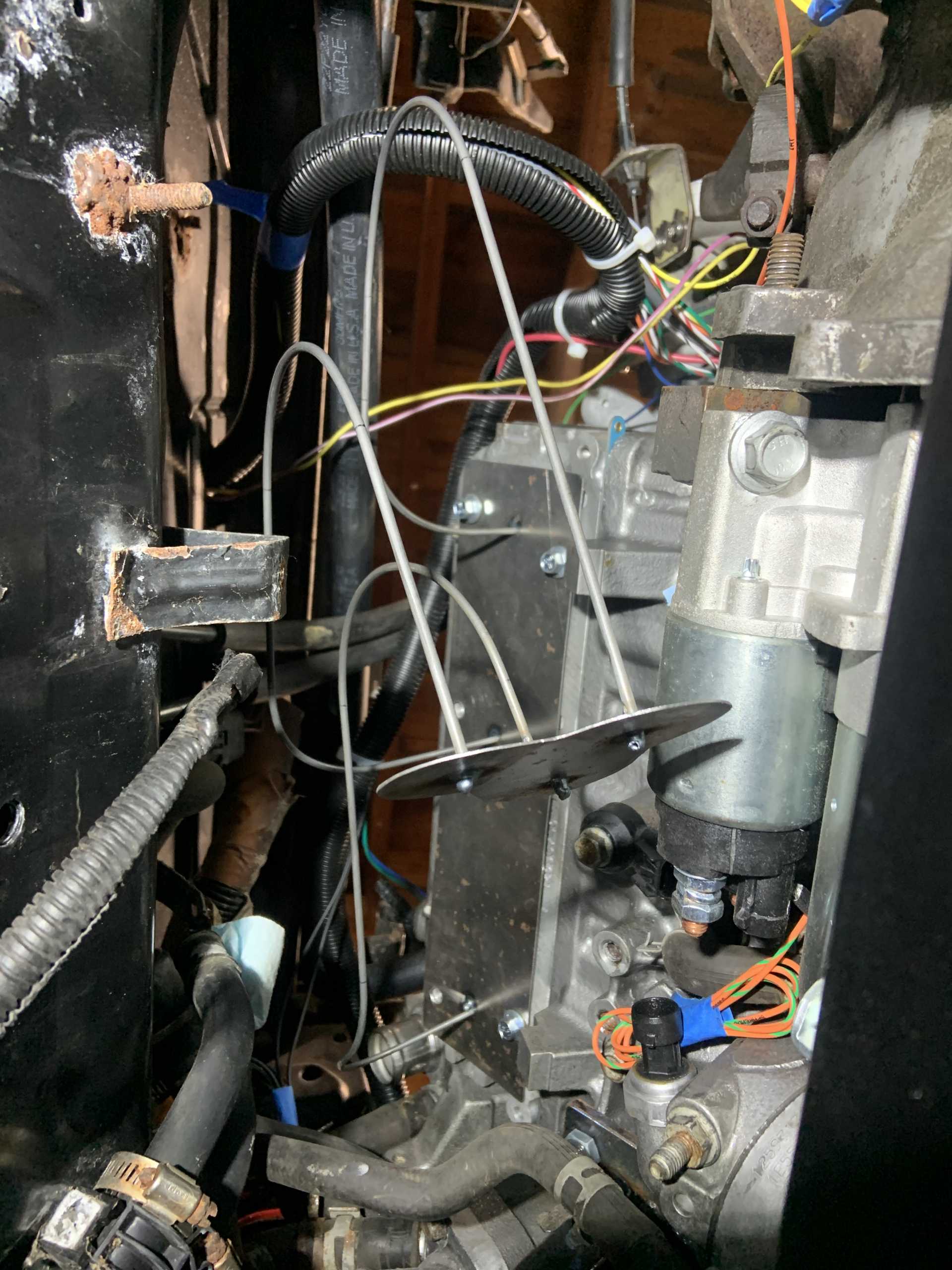
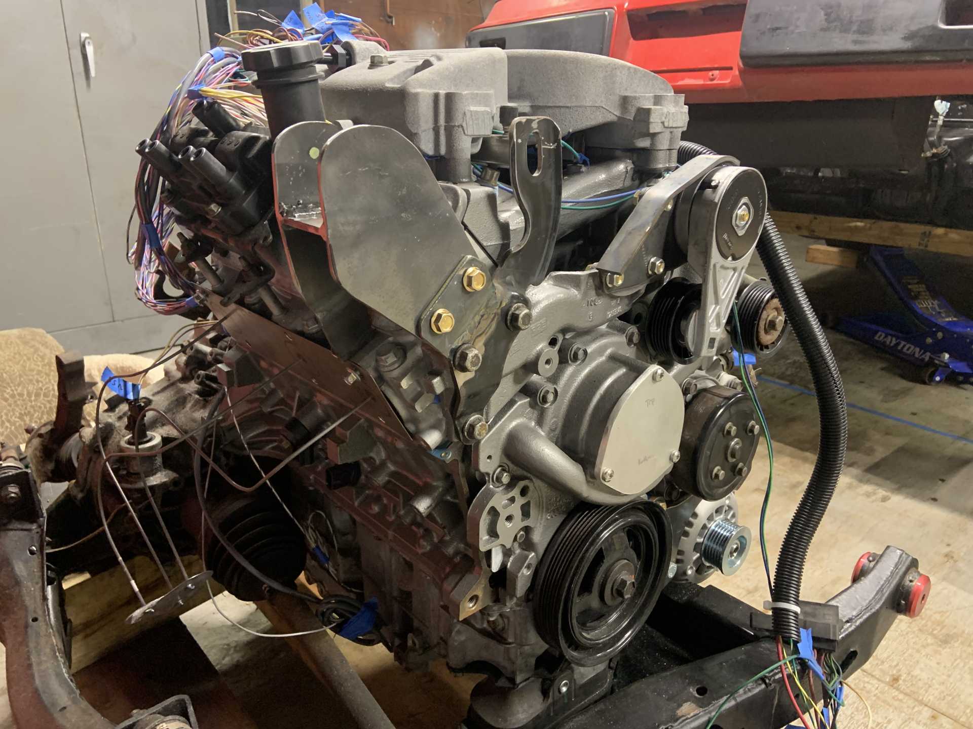
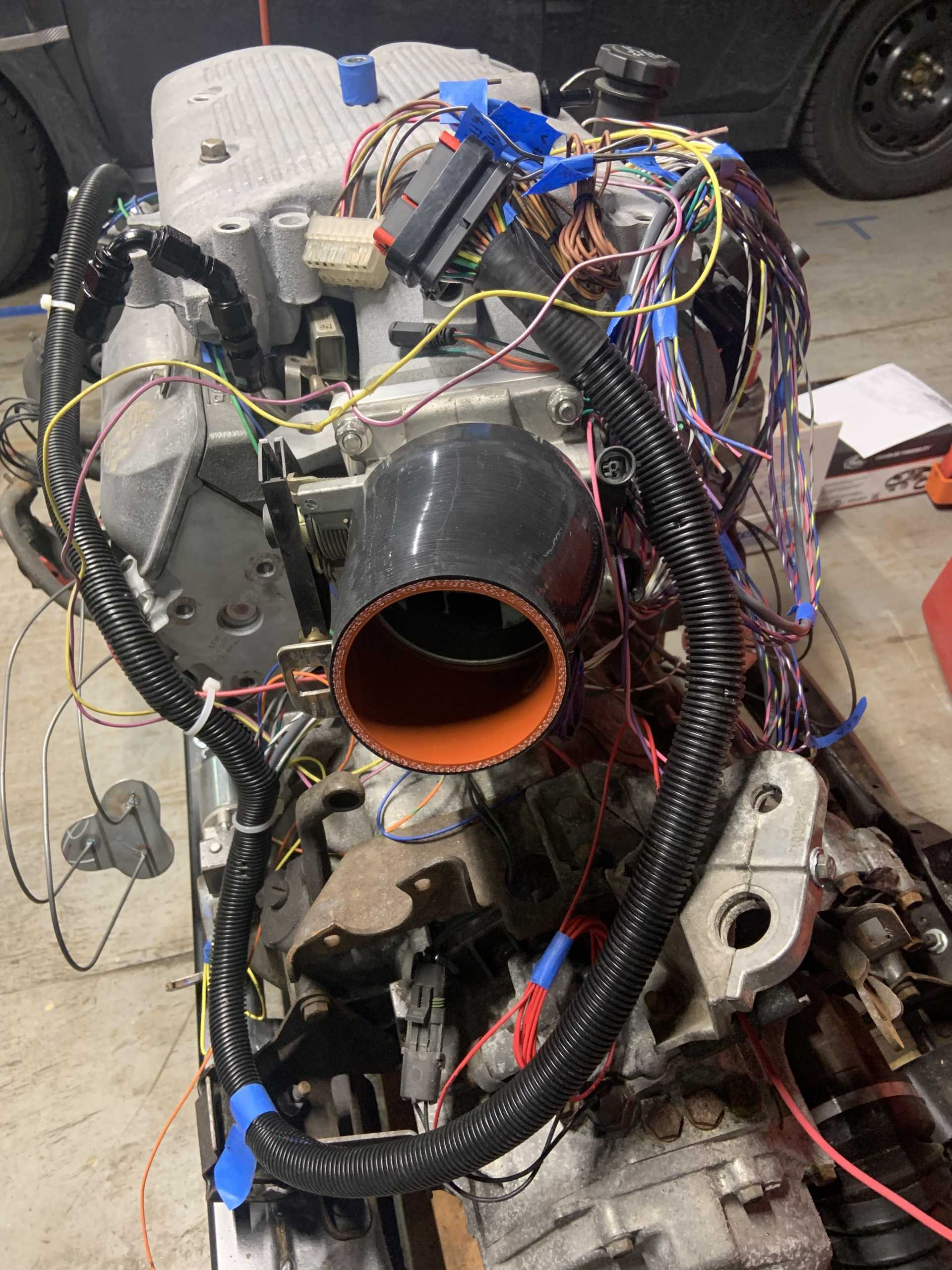
I then started laying out the harness on the motor and routing all the wires where they need to go.
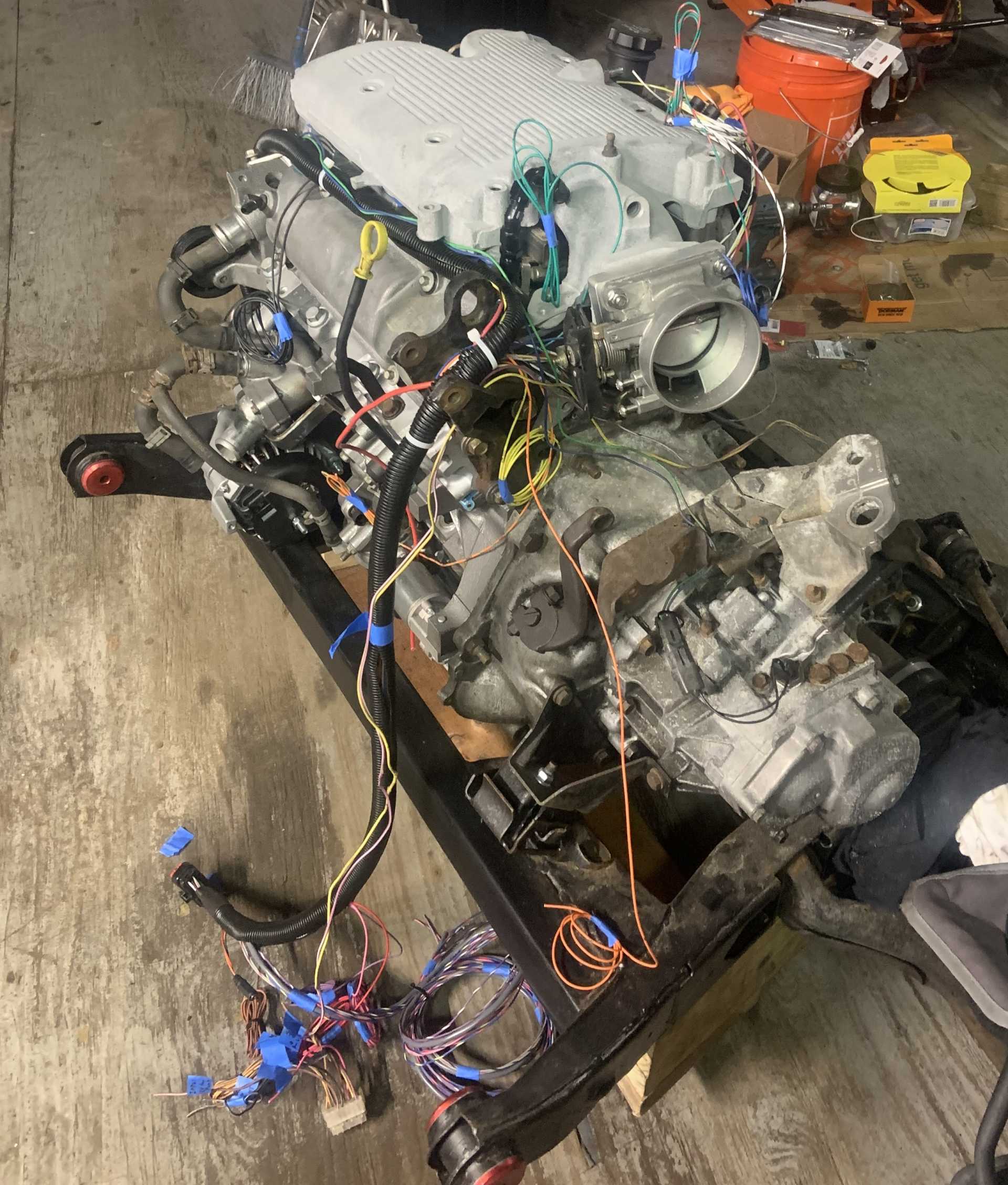
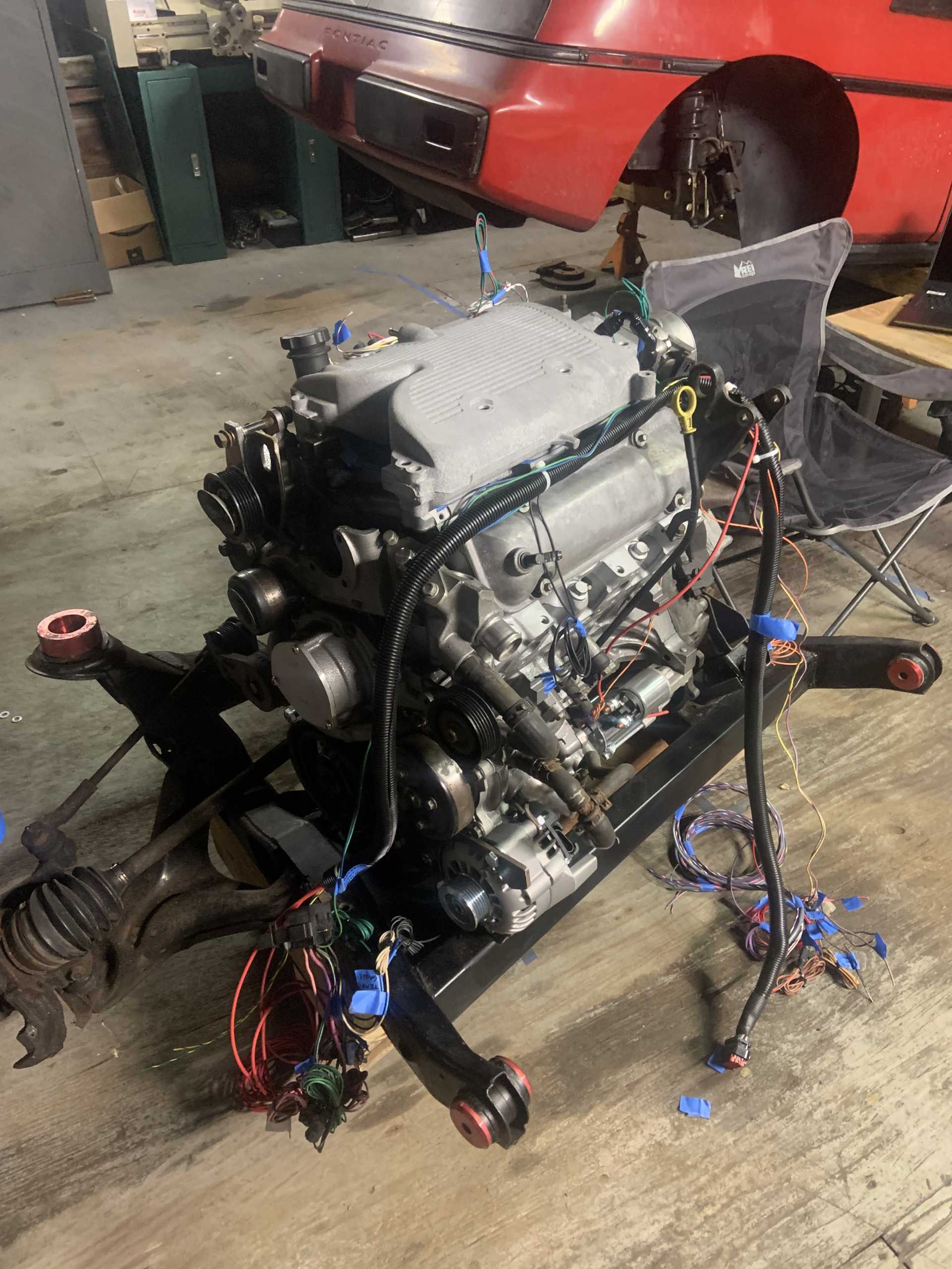
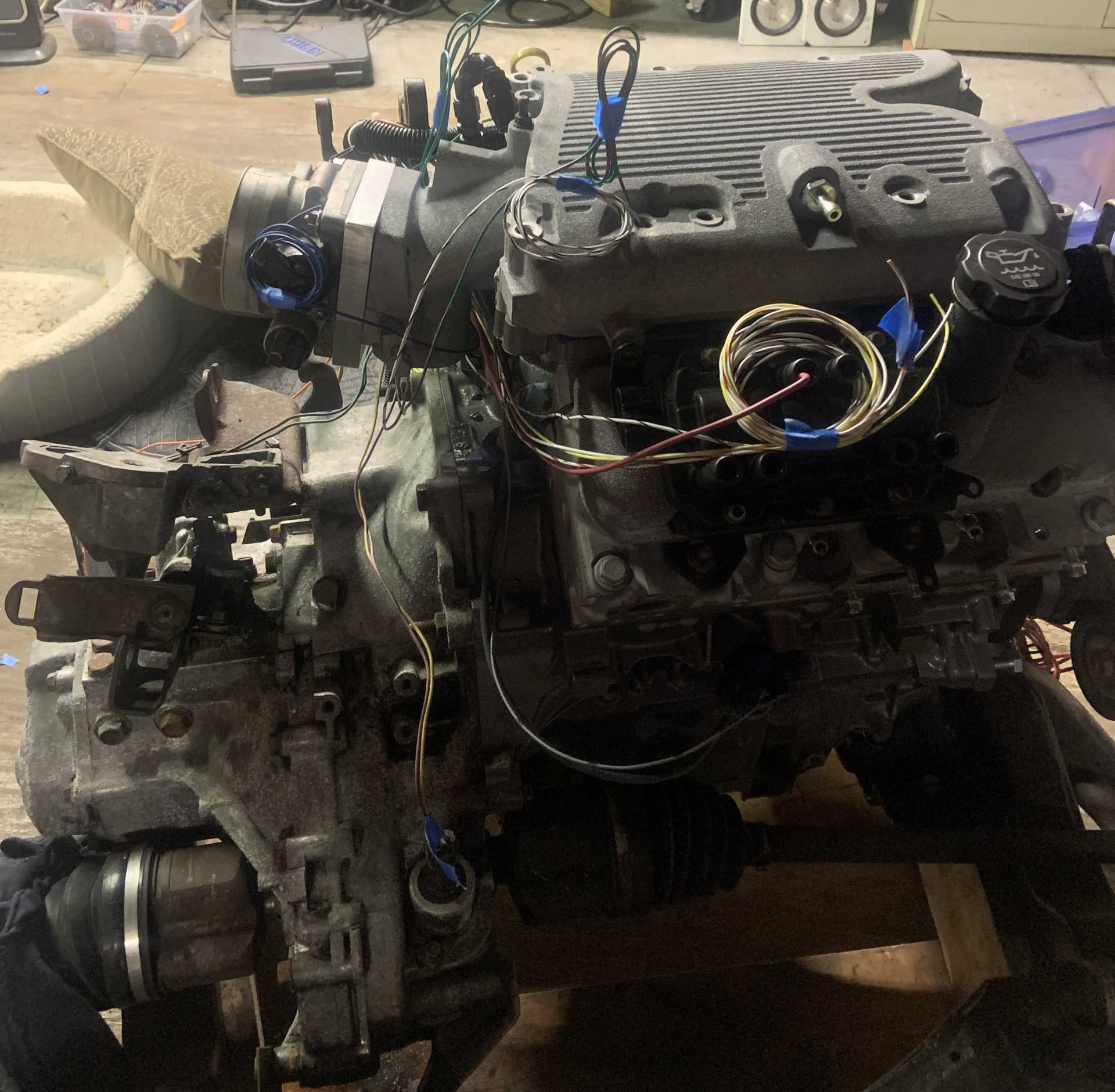
Still working on this but going to start cutting and splicing wires and crimping things soon, I already have all brand new connectors for everything. I need to get a new connector for the 3 wire coolant temp sensor that I need to buy.
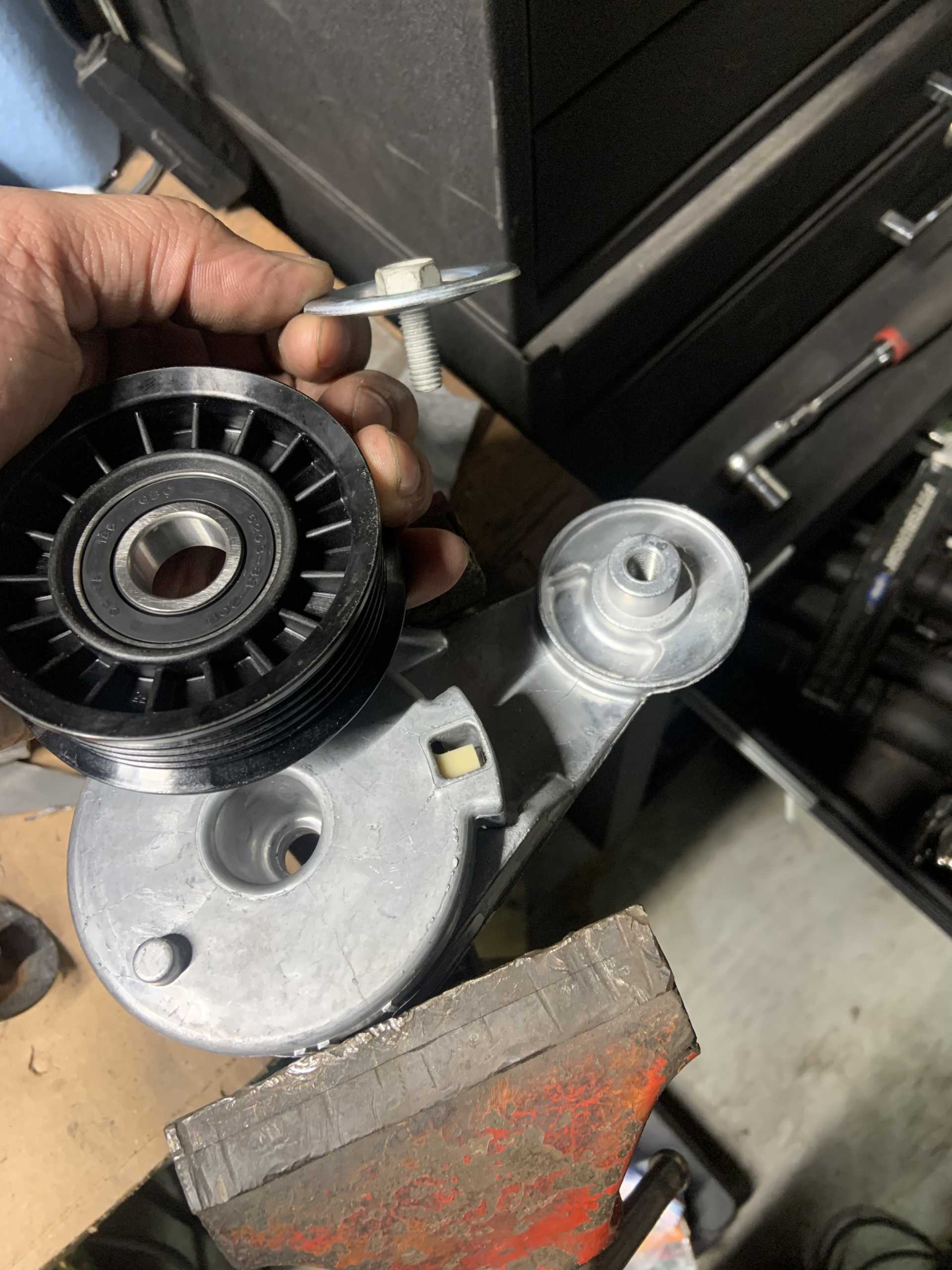
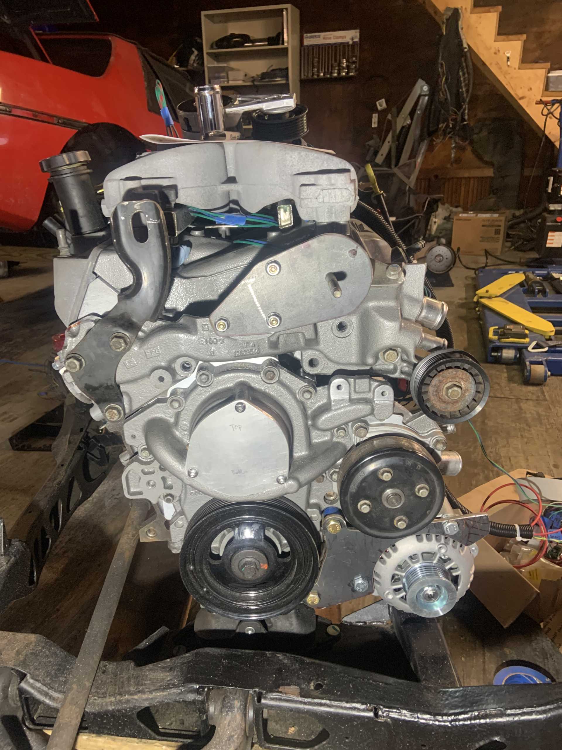
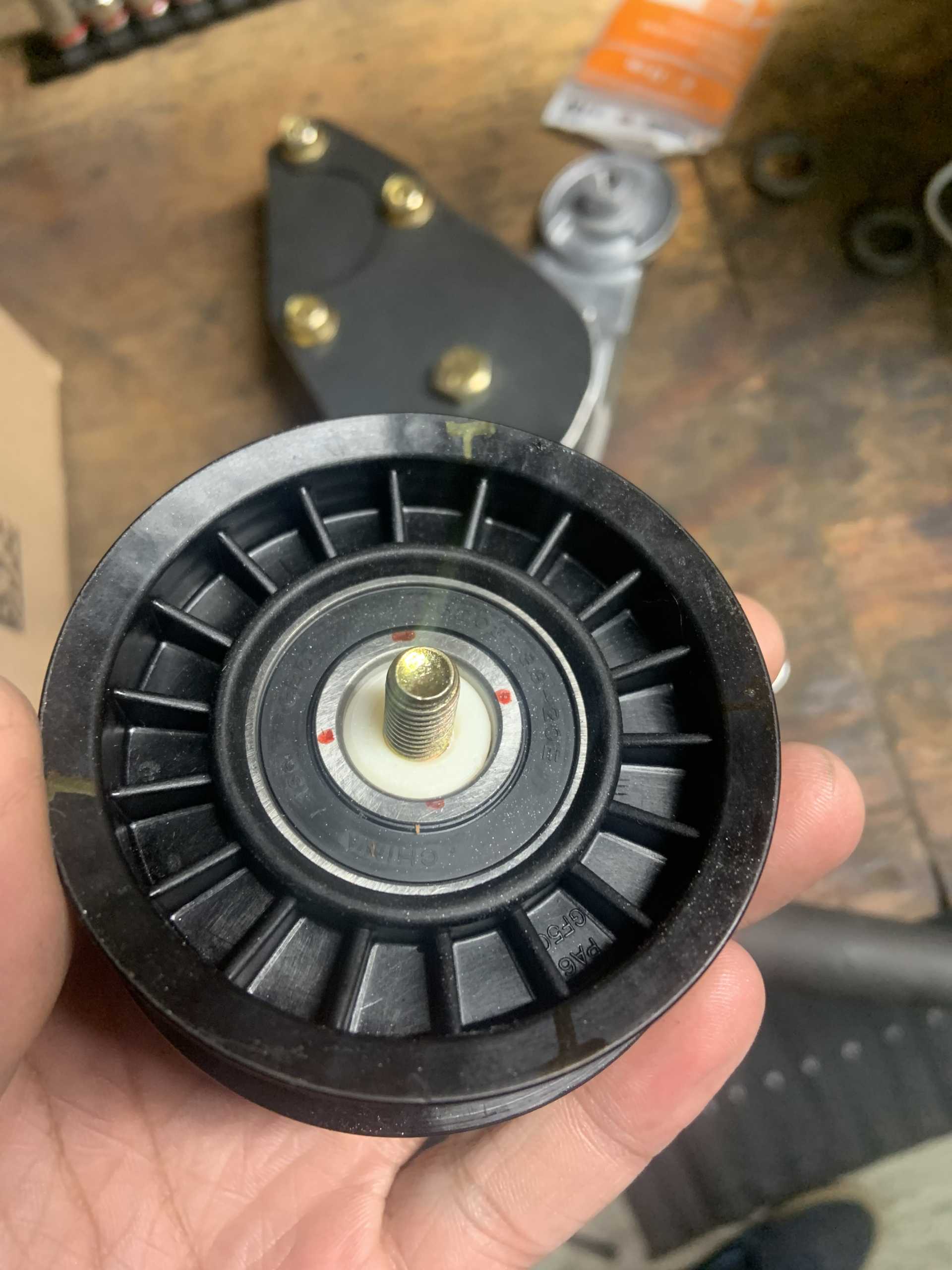
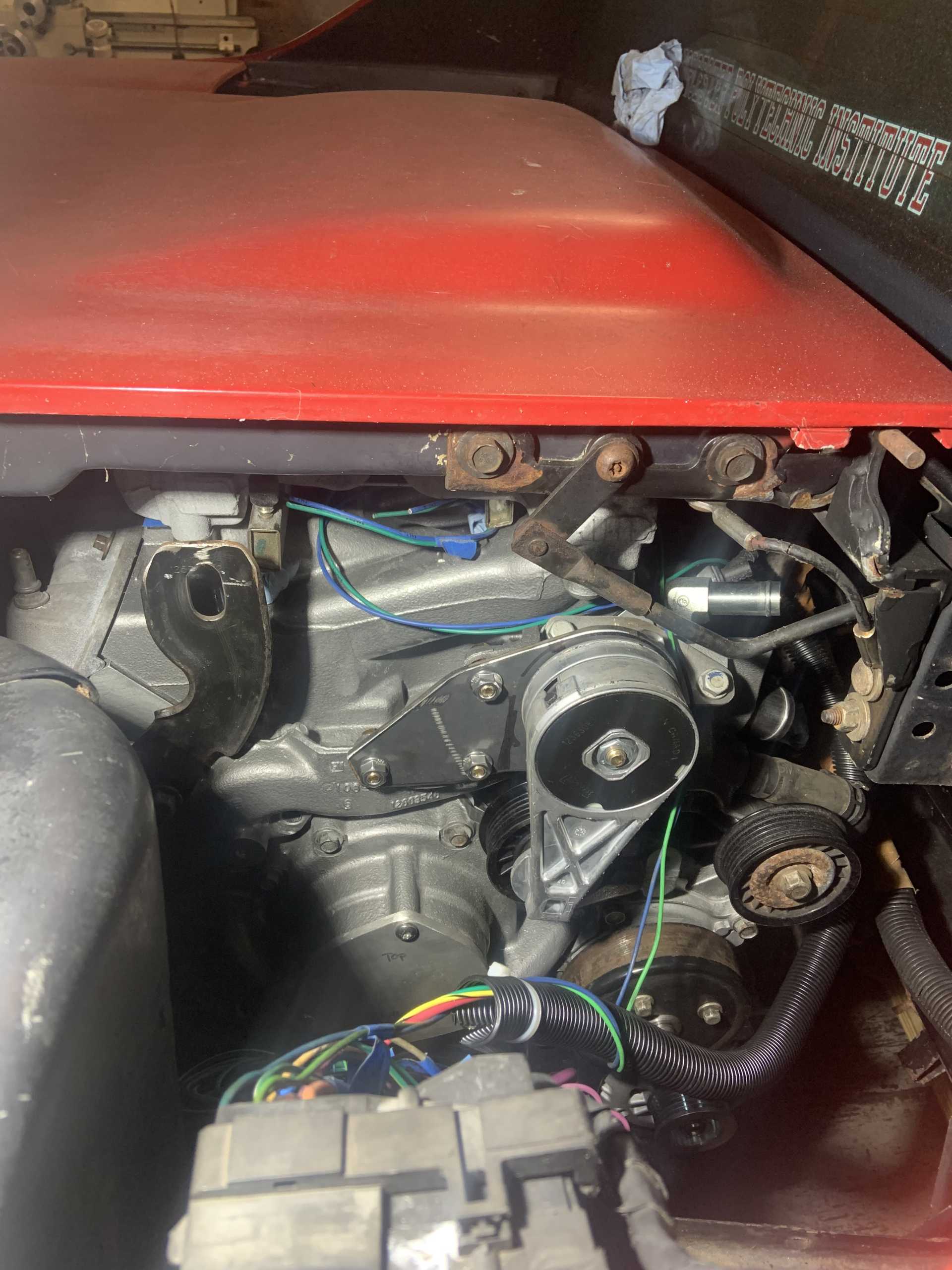
And I figured out a better belt routing solution that seems low effort, I needed a tensioner that tensioned clockwise instead of counterclockwise like the LZ9s, but the 3400 tension fit the bill perfectly so one of those is arriving soon.
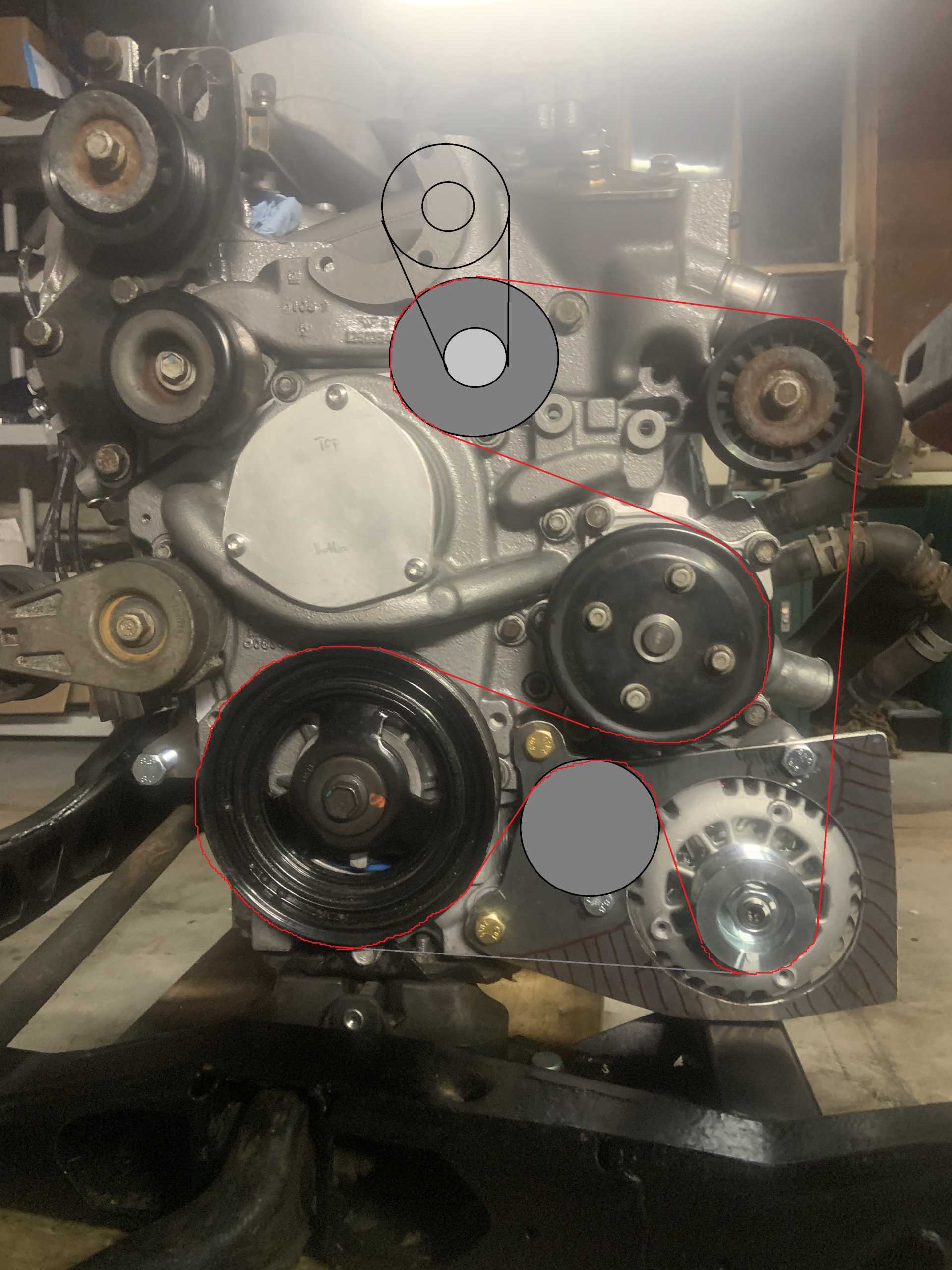
I may need to make a bracket for it that bolts to the original power steering pump mounting locations, but there is a chance it all lines up and I can drill into the PS mounting bracket and bolt it up, maybe with a small spacer.
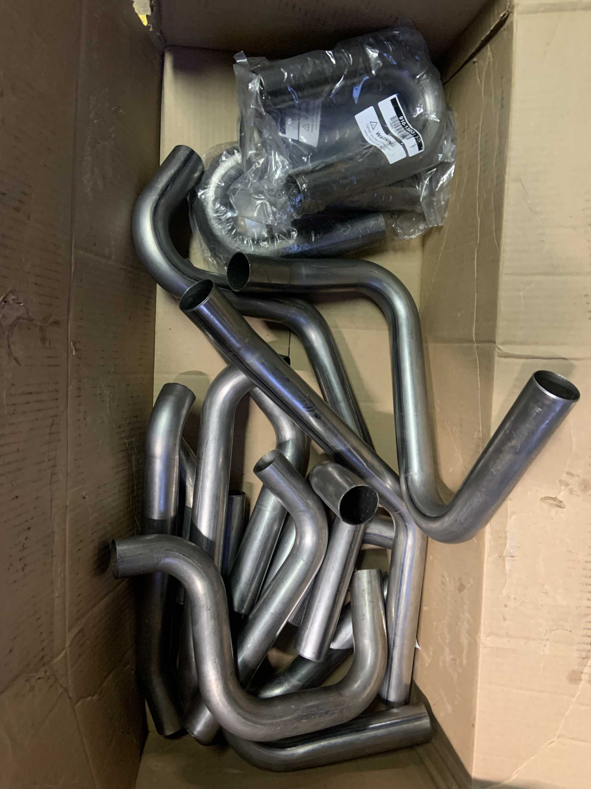
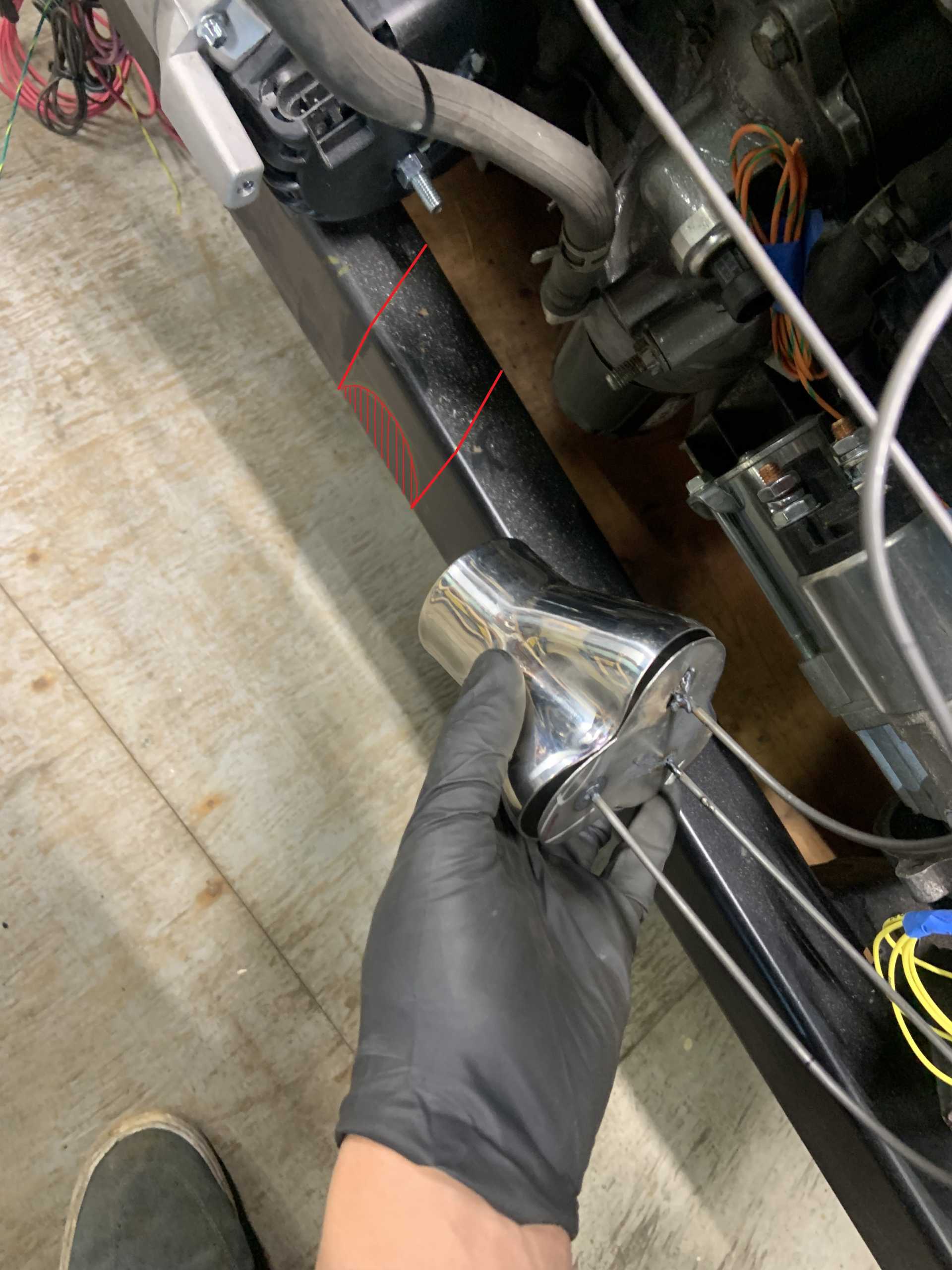
And finally, I ordered everything I need to make my headers, I got some V6 collectors from the UK, a selection of mild steel 1.75" tubing and bends, and some V bands to attach the headers to the rest of the exhaust. I plan to get the headers Jet-Hot ceramic coated, they quoted me $400 including shipping, and recommended mild steel for the header material. My header routing plan is no longer to cross over the transmission, and instead have the firewall side header exhaust travel under the motor between the oil pan and motor mount, I need to notch the crossmember I made and probably add a little support for it. It is a little tight with the alternator and oil filter being where they are, but I mocked it up and it should work fine. It will be a 2.5" tube that runs through there.[This message has been edited by zkhennings (edited 02-13-2023).]
|
|
|
|
zkhennings
|
FEB 18, 12:38 PM
|
|
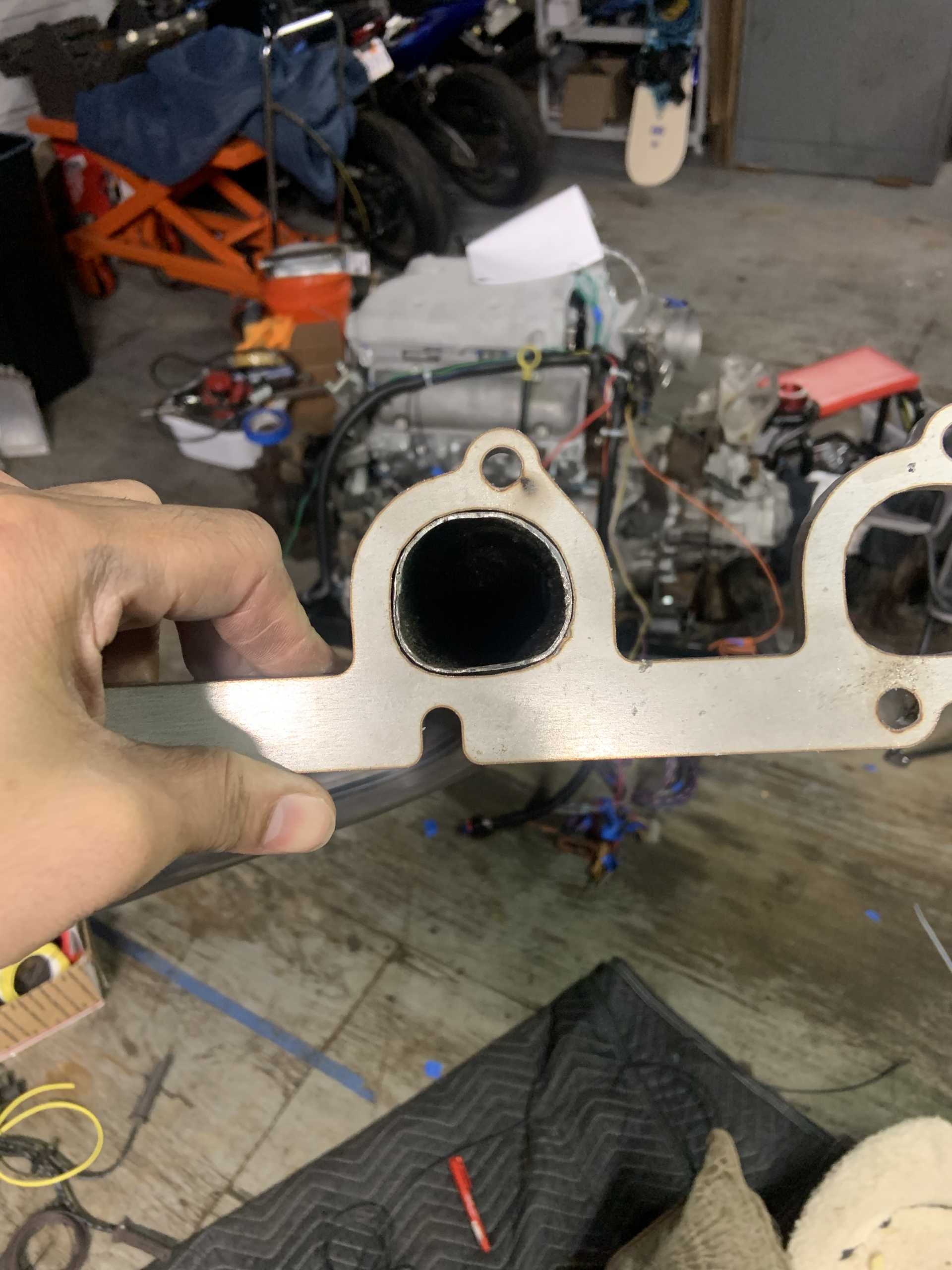
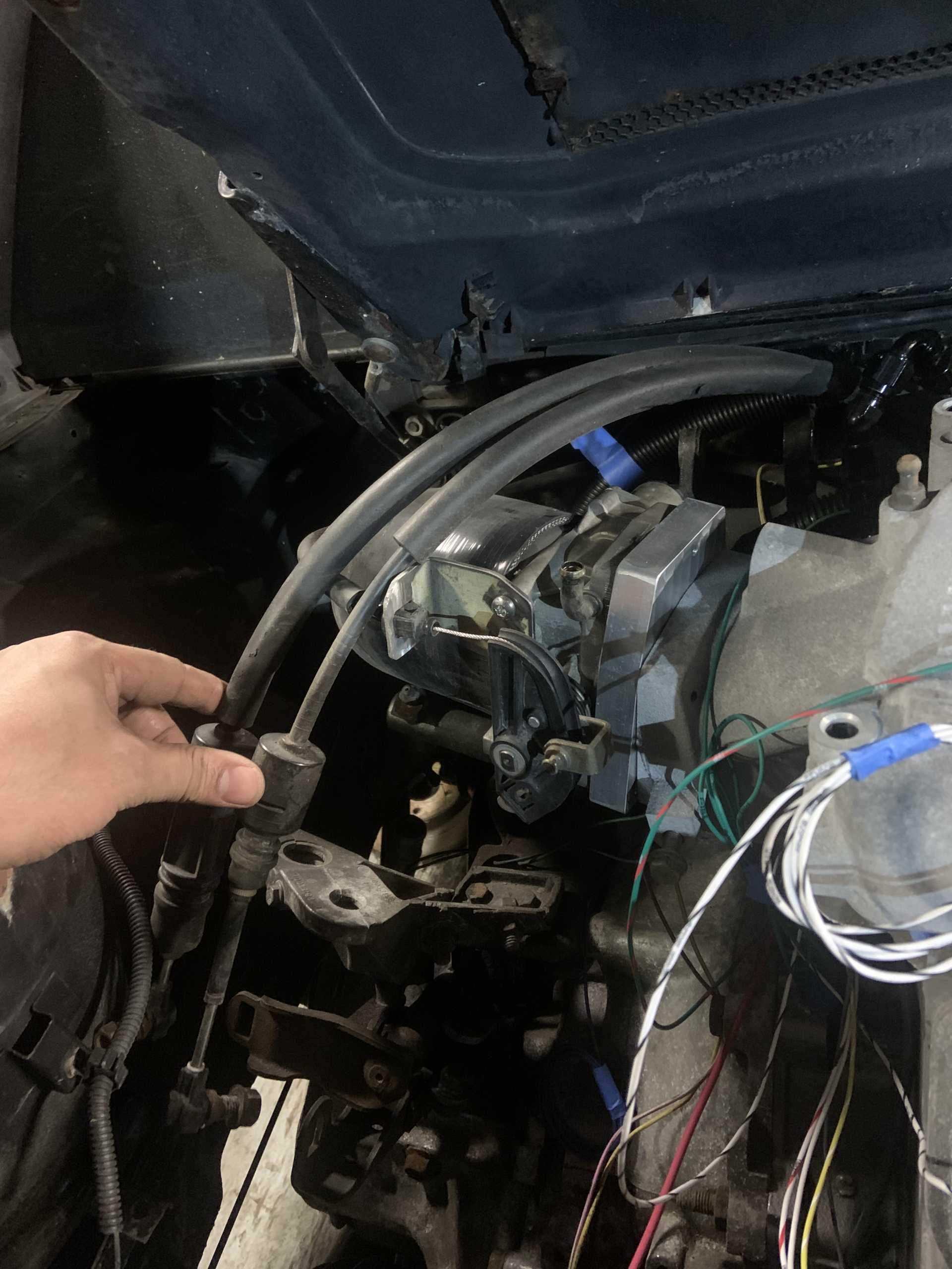
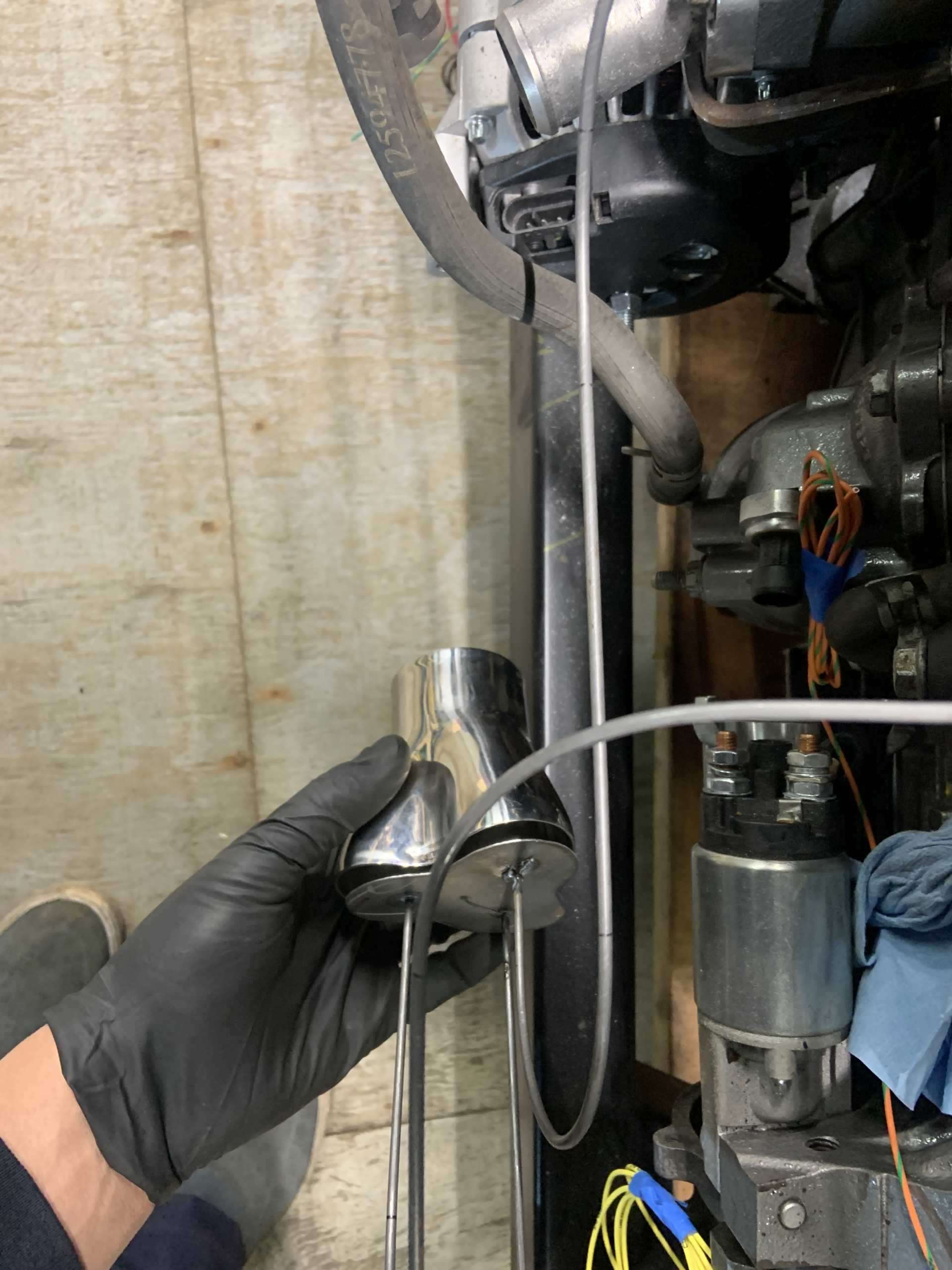
Exhaust tubing came in, did not take much persuasion to get the tubing to fit Eric's flanges.
Made a throttle cable bracket to use the 2.8 throttle cable with the Northstar TB.
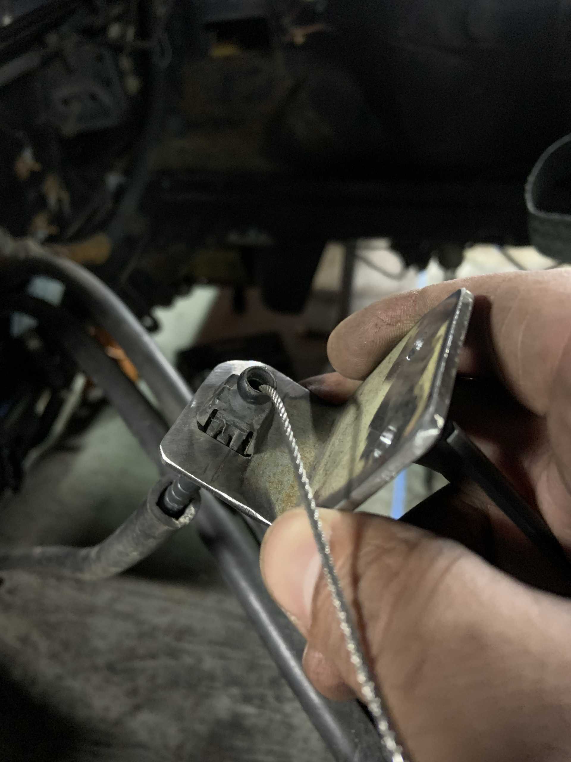
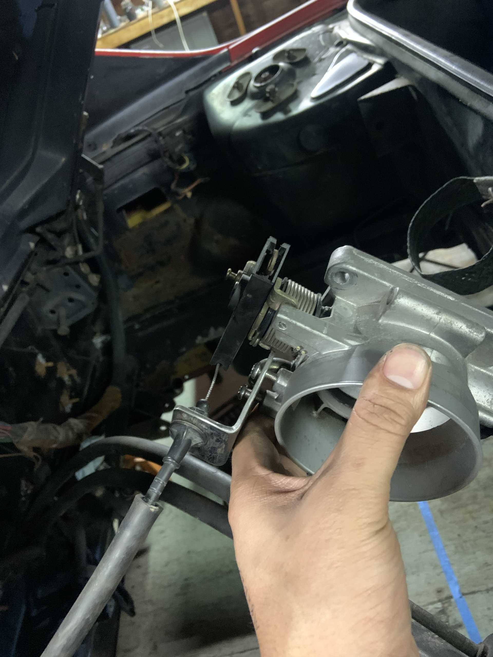
I played with flipping the TB upside down to get a less extreme bend on the throttle cable, but due to the offset of the flange relative to the throttle opening, it may mess with my Isuzu shift cables. Something to test fit.
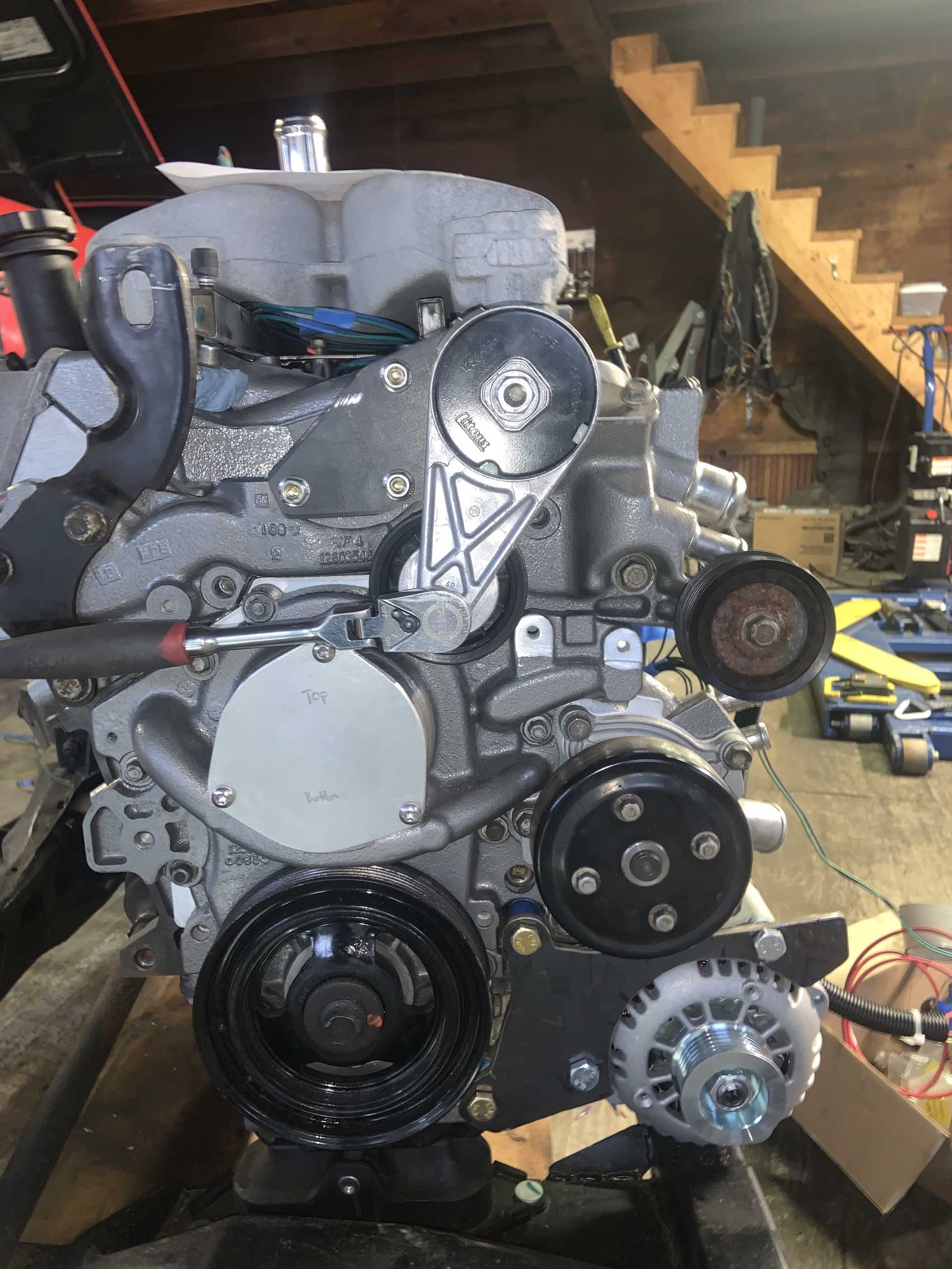
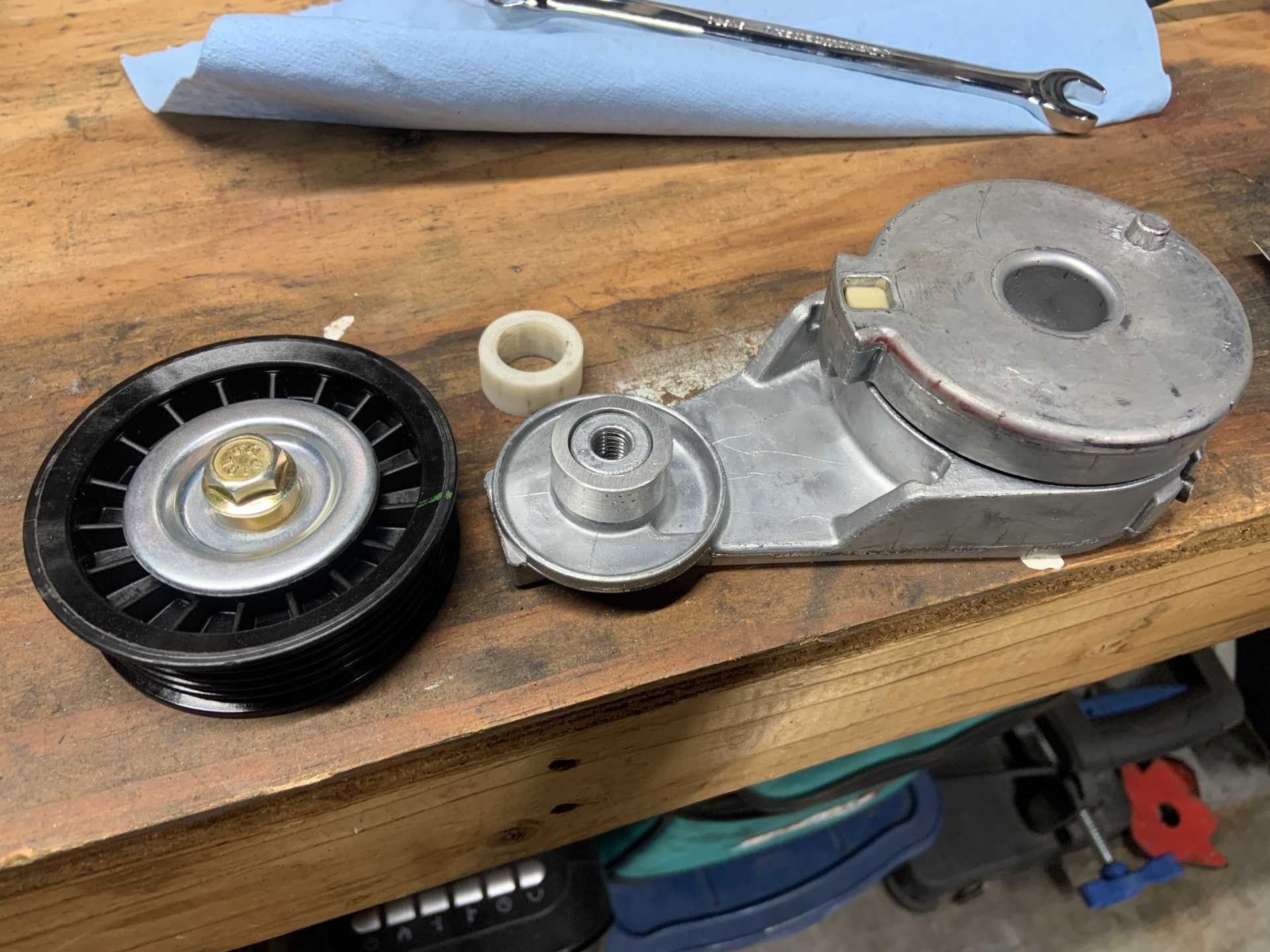
I also worked on the tensioner. I did some CAD and messed with placement and ended up around here.
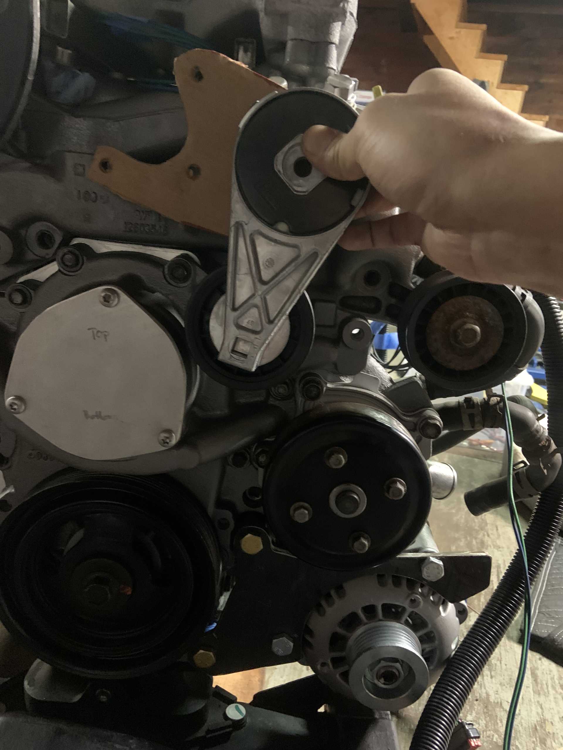
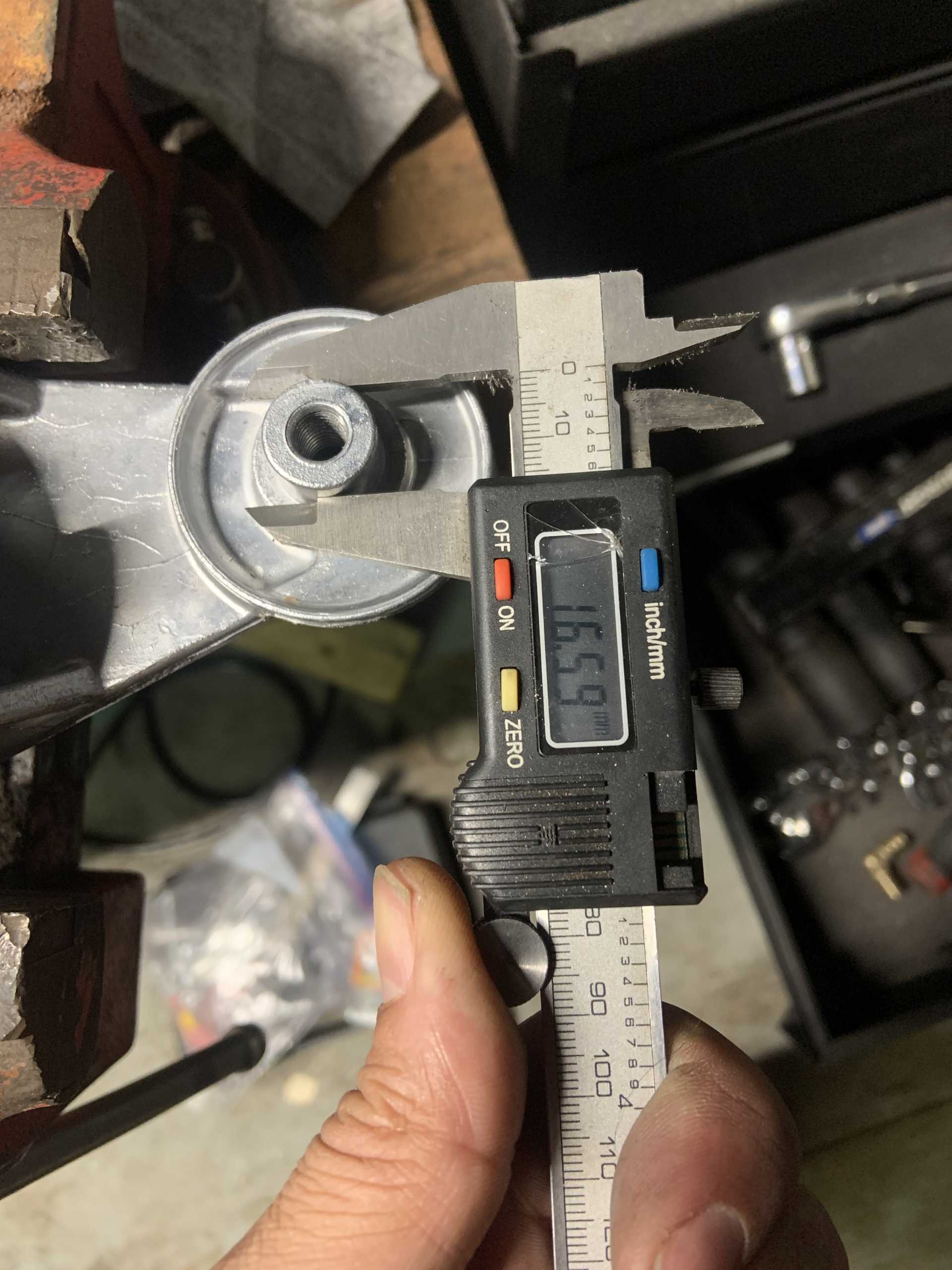
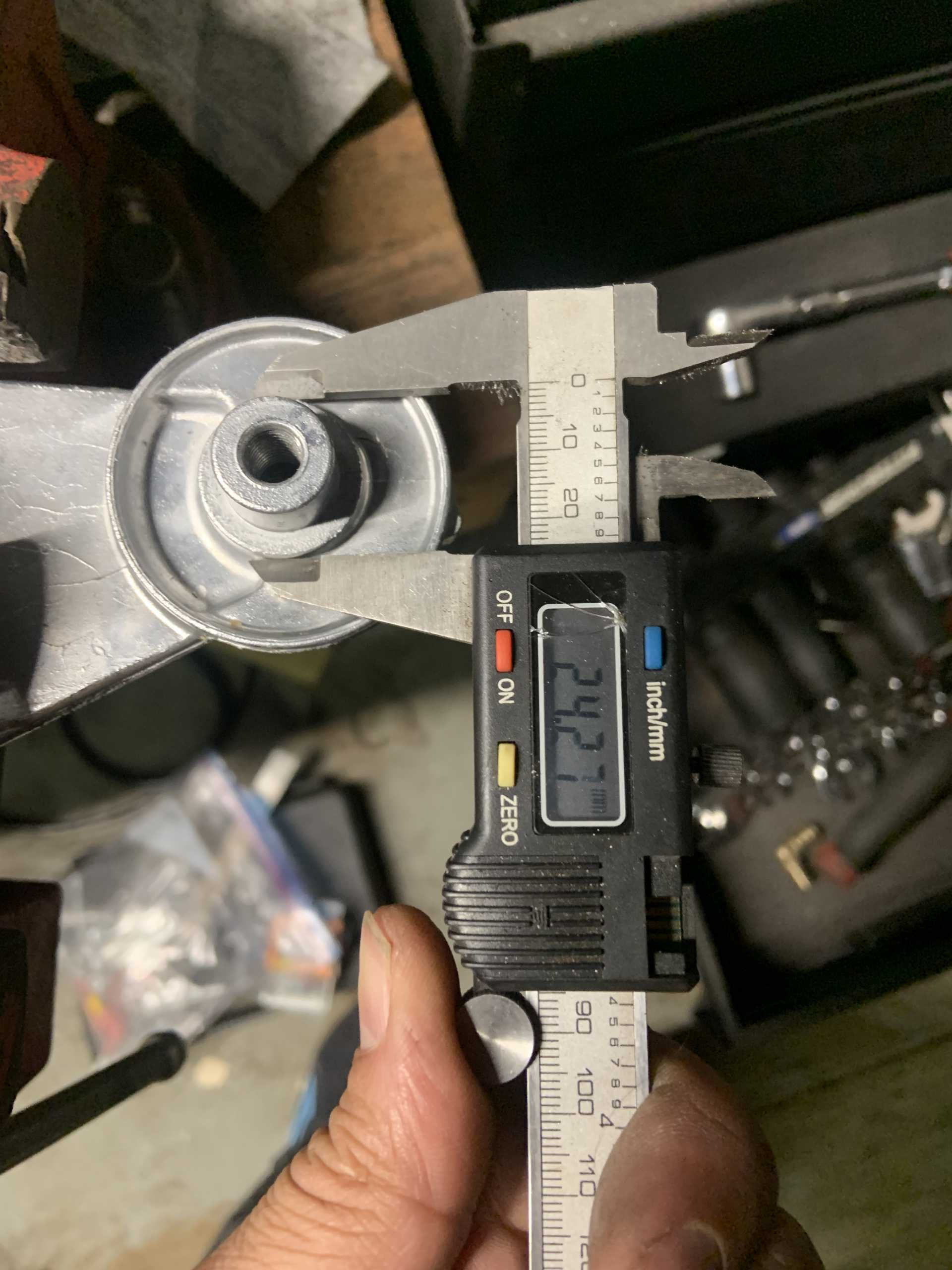
In order to get the pulleys to line up, I need to offset the pulley that is attached to the tensioner.
I then chopped the offending bosses down on the timing cover. I filed the right boss back to flat since I could use that spot to mount something. The left boss is covered by the pulley so I just smoothed it.
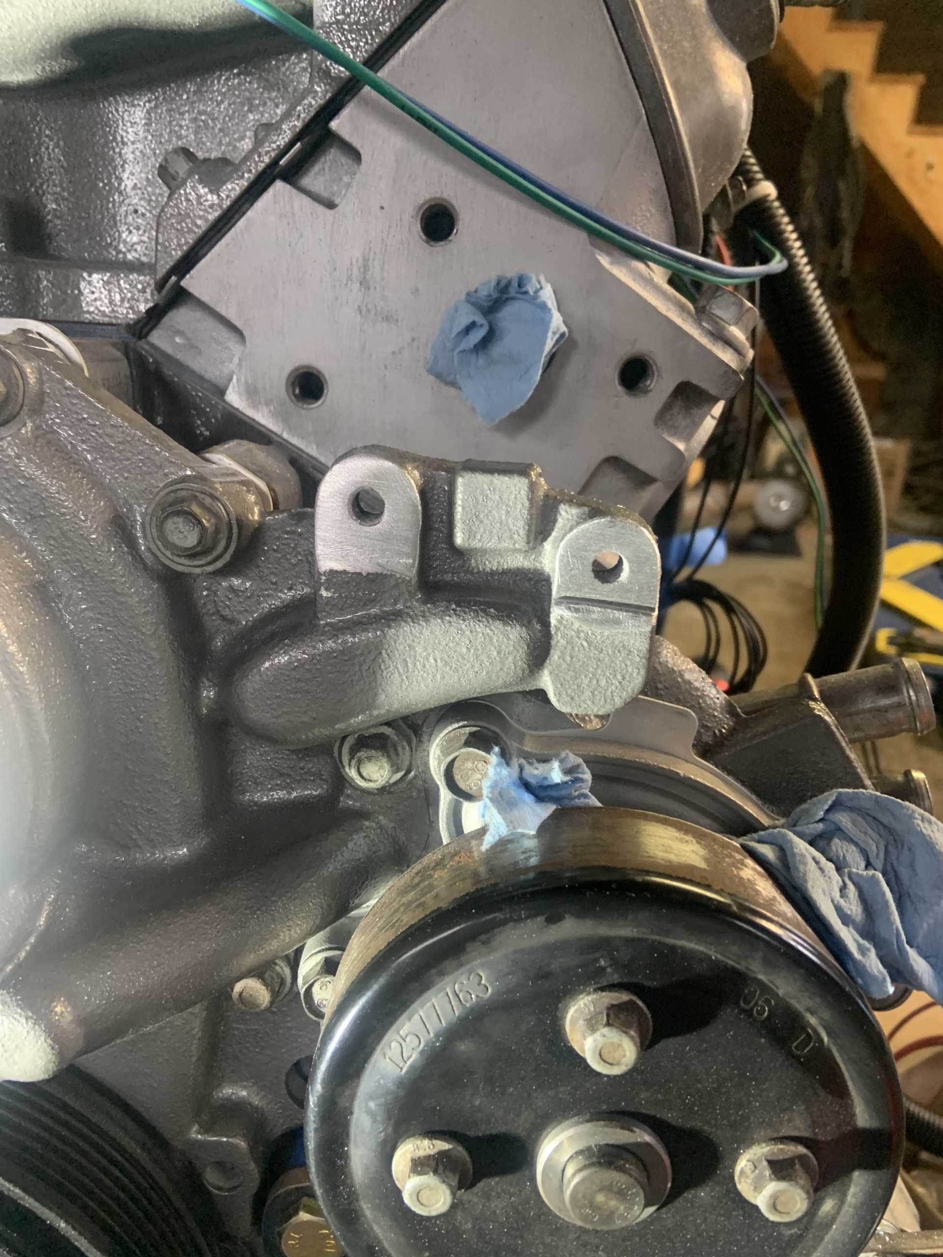
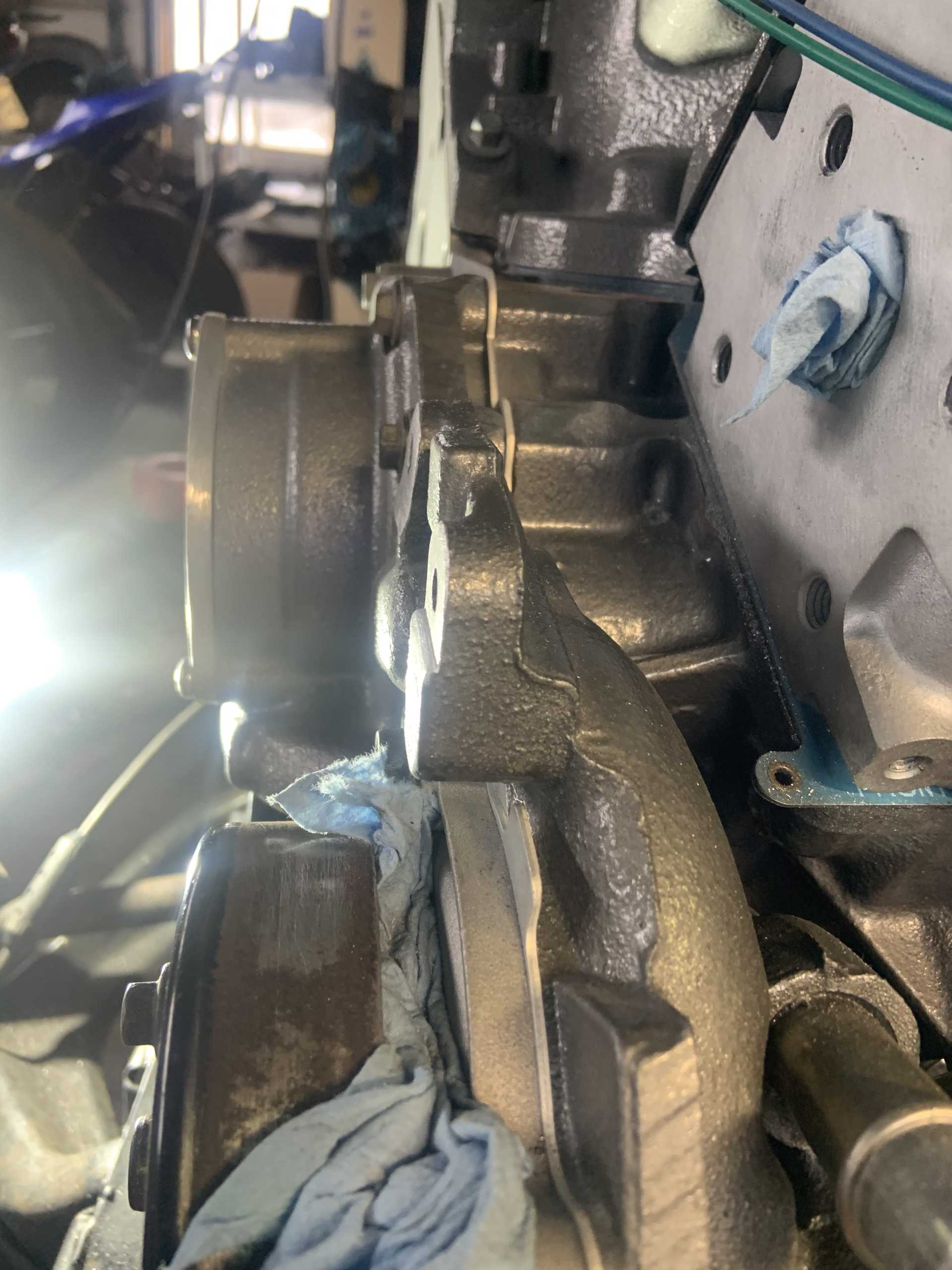
I chopped up the crossover to remove the alternator mounting features I was planning to use for the dogbone. Seems to be a bad idea so I will make one with steel. I regret that I cut off the boss for one of the idler pulleys, now I am forced to get my tensioner positioning to work and it is not as straight forwards as it first appears.
Did some more CAD and placement as I found the pulley interferes with the water passage below the left boss. I had to raise the pulley pivot and then position it to clear all the coolant fill business.
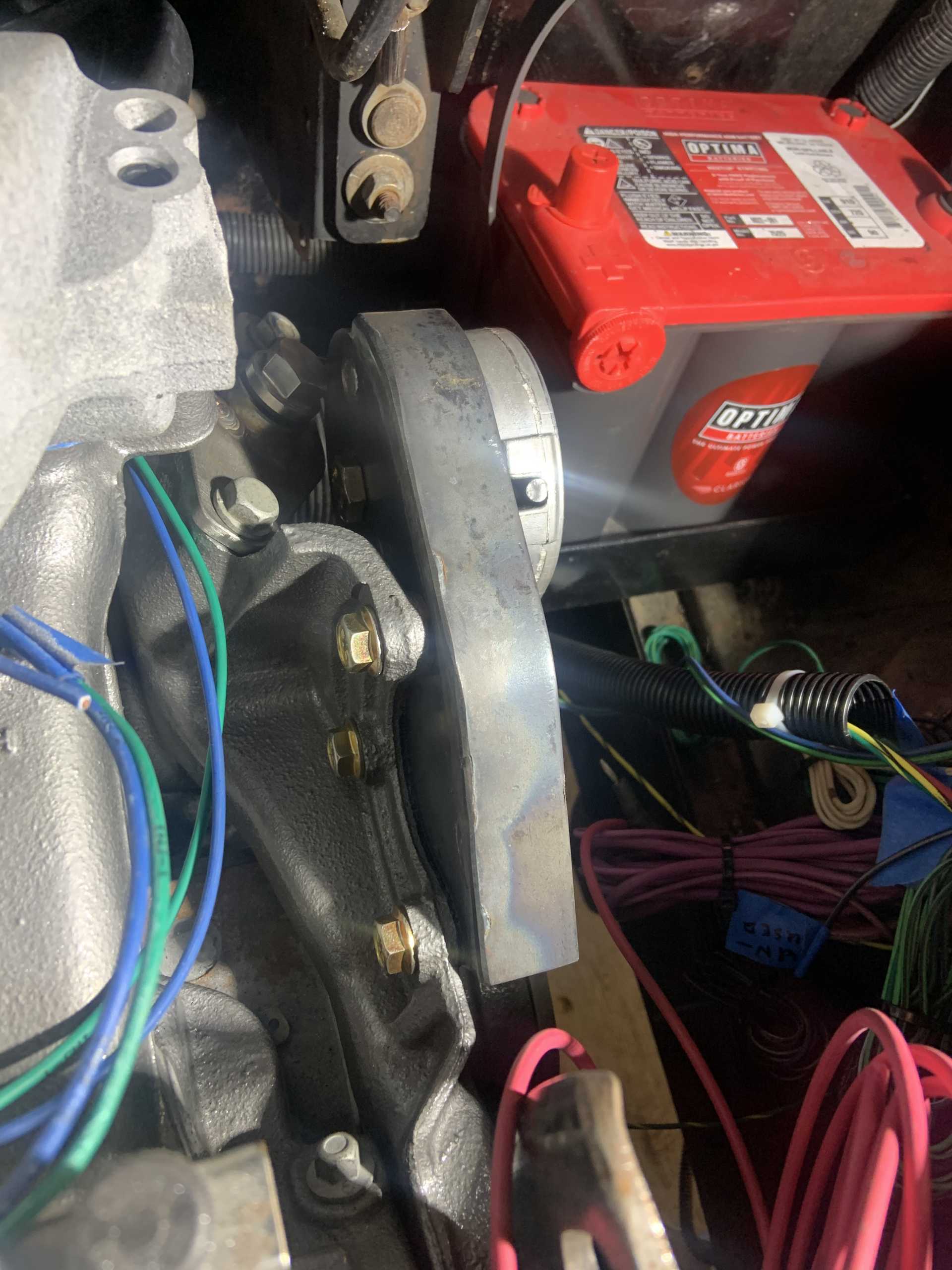
Tensioner positioning after new discoveries.
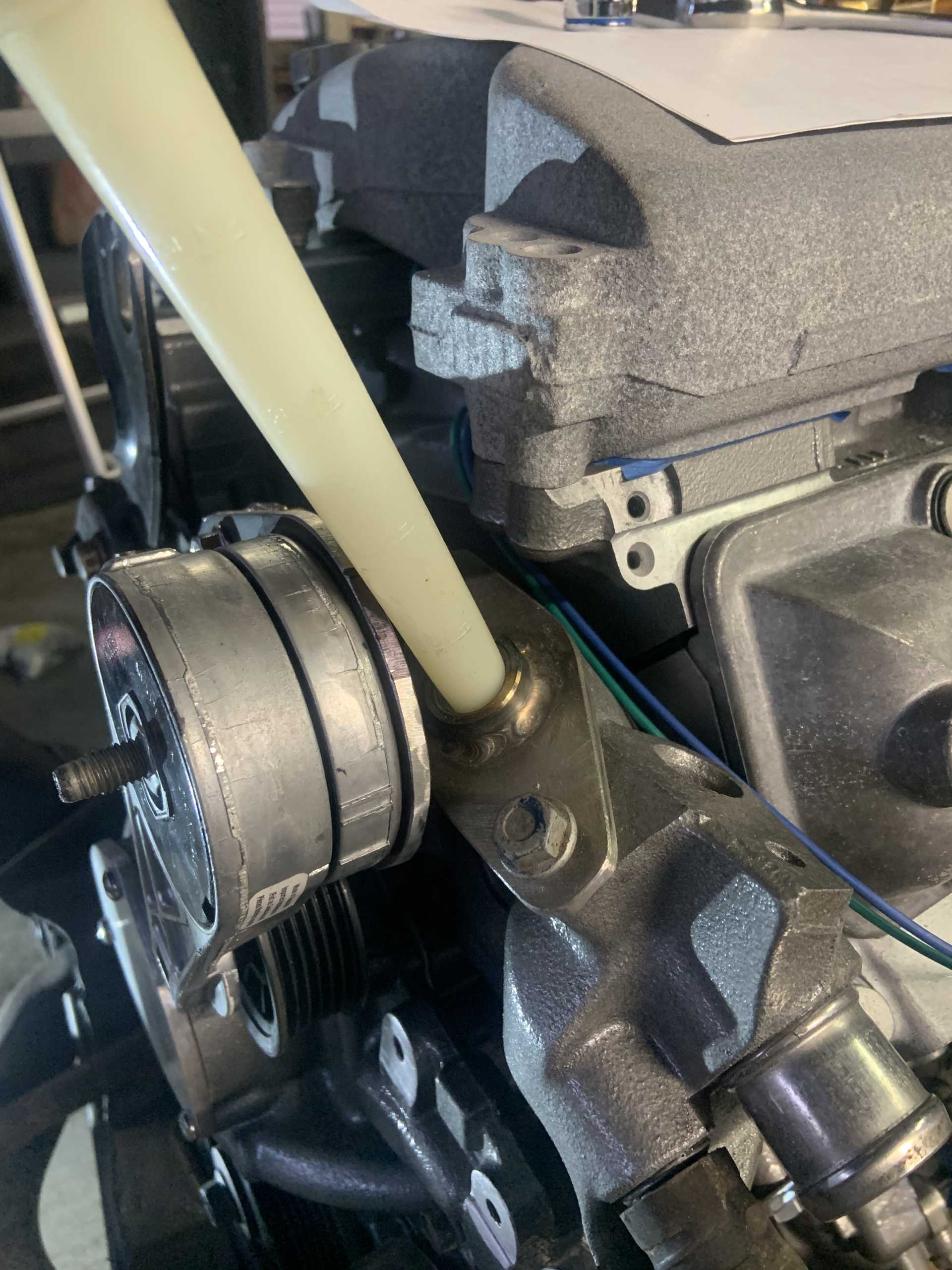
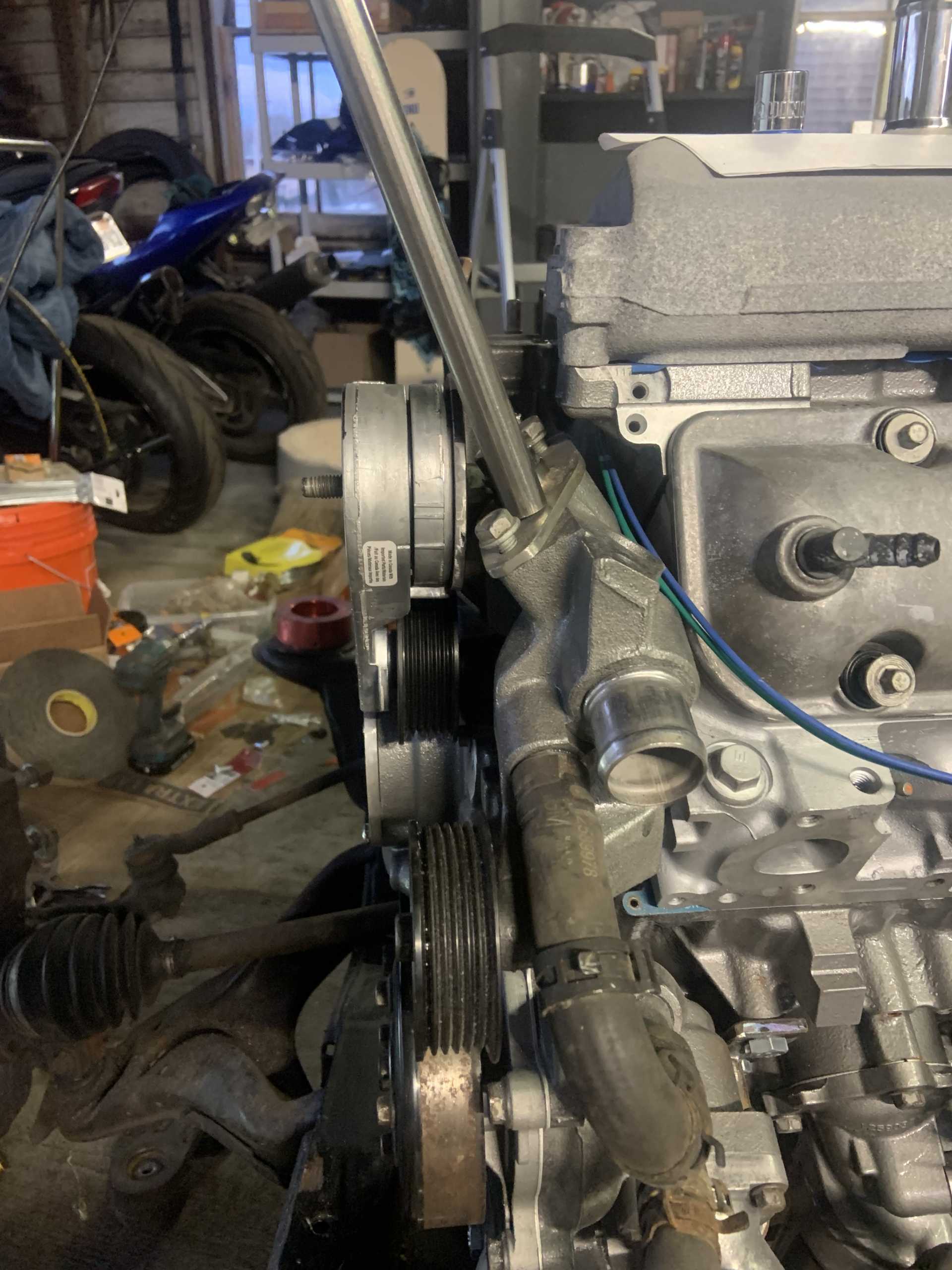
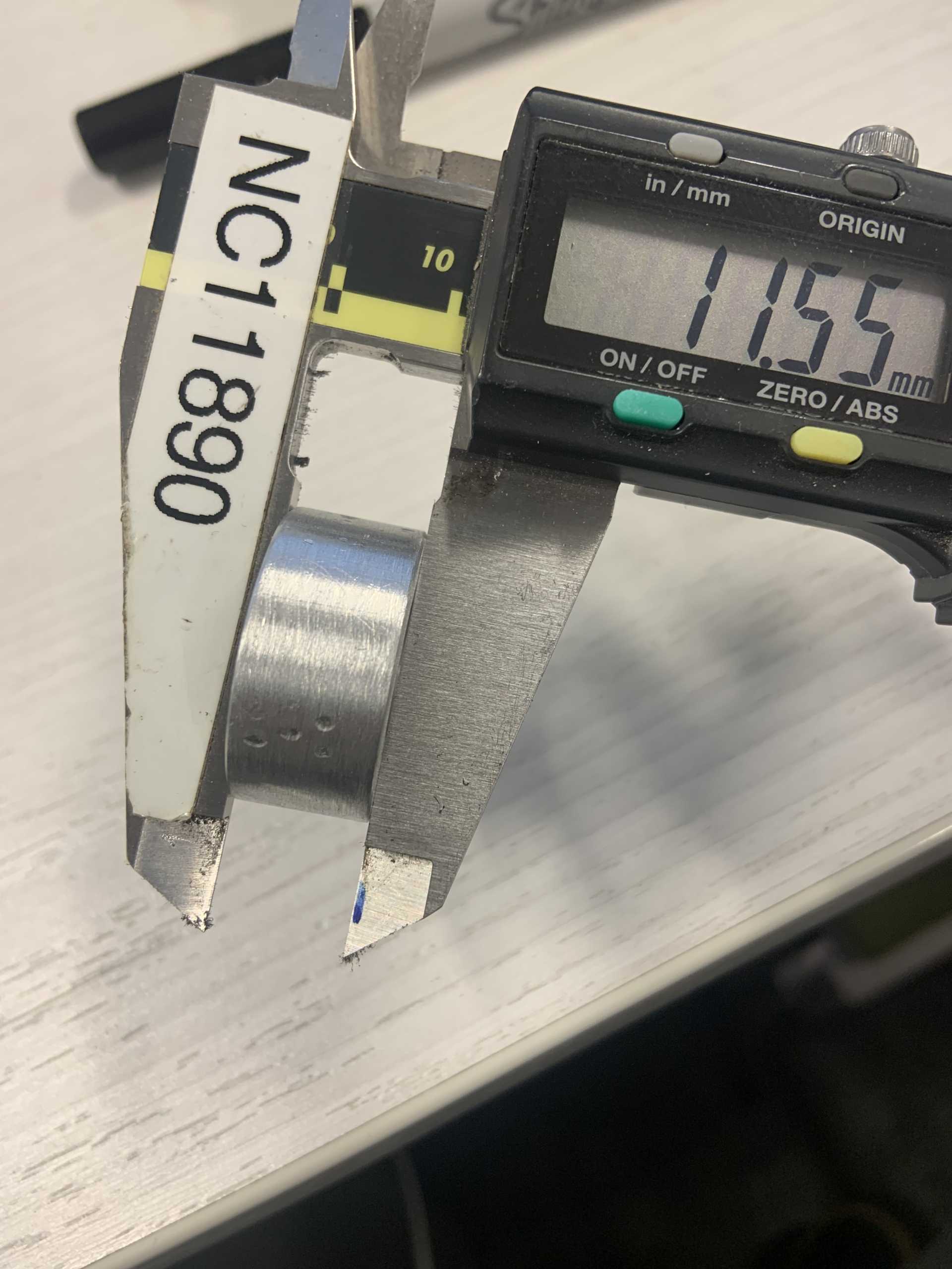
It can be seen below how close the upper timing cover bolt head is to the pulley. This pulley still needs to be spaced out an additional 2.90mm, so I will have to change the clocking slightly to allow the pulley to not cover that bolt. It is right at the edge of the pulley so it shouldn't take very much at all.
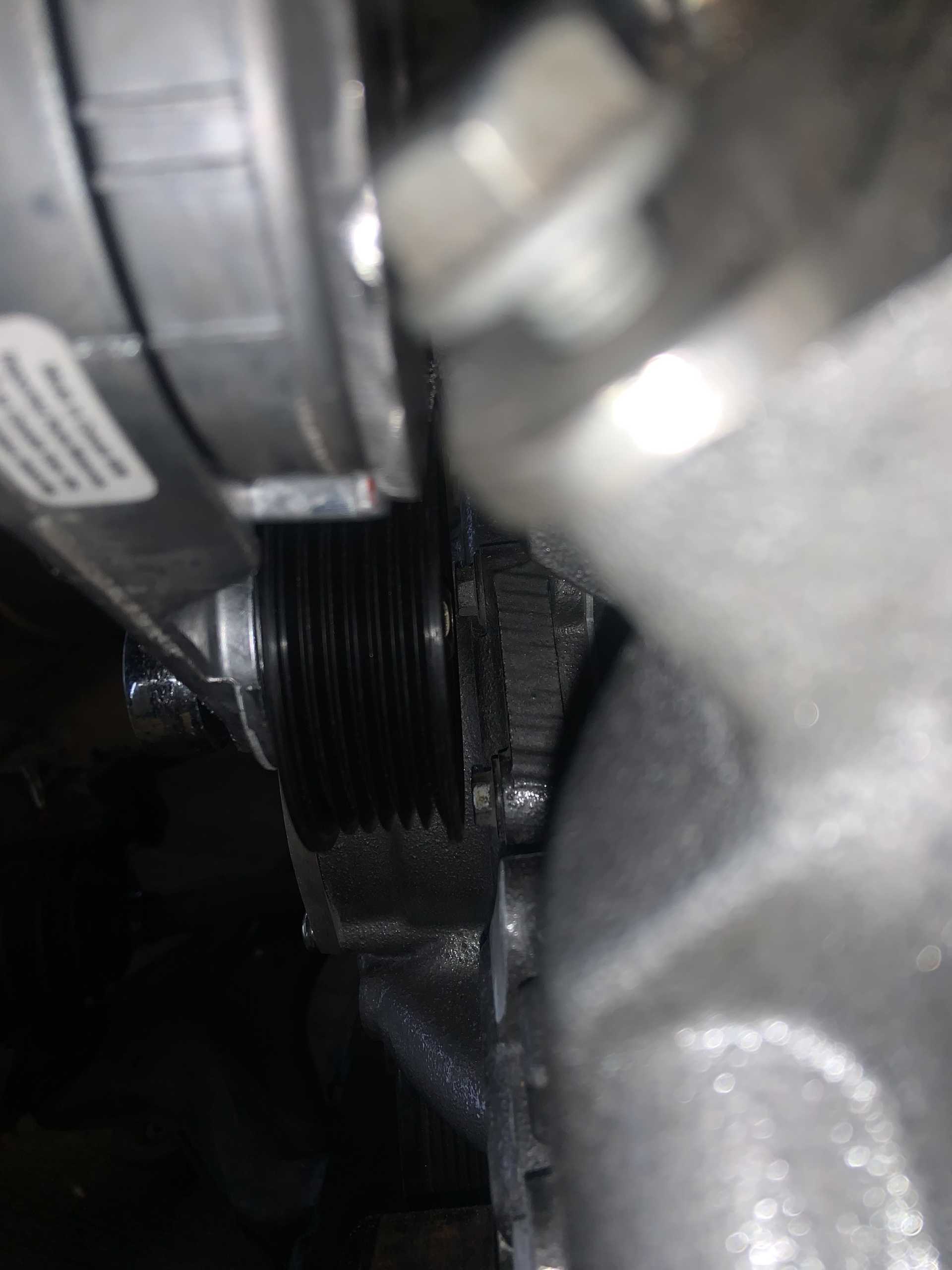
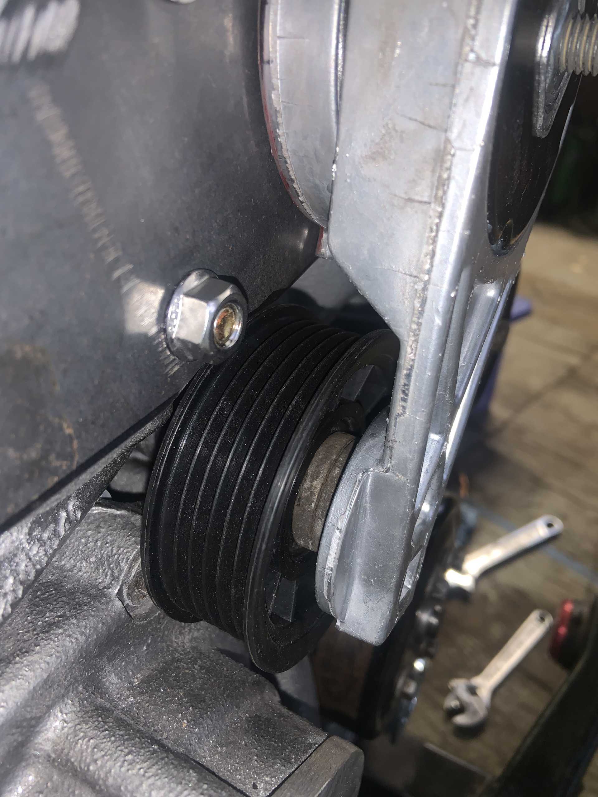
Here is the current spaced off tensioner pulley, I am using the strut bolt washers, it is spaced out about 5/16" currently and just needs a little more. Probably will end up at 7/16" spacing. You can also see the offending bolt head poking out from behind the pulley. Won't take much to clear it.
Tensioner has good range, it can go even farther too and still be tensioning. I wanted it to have a lot of range to make belt changes easy.
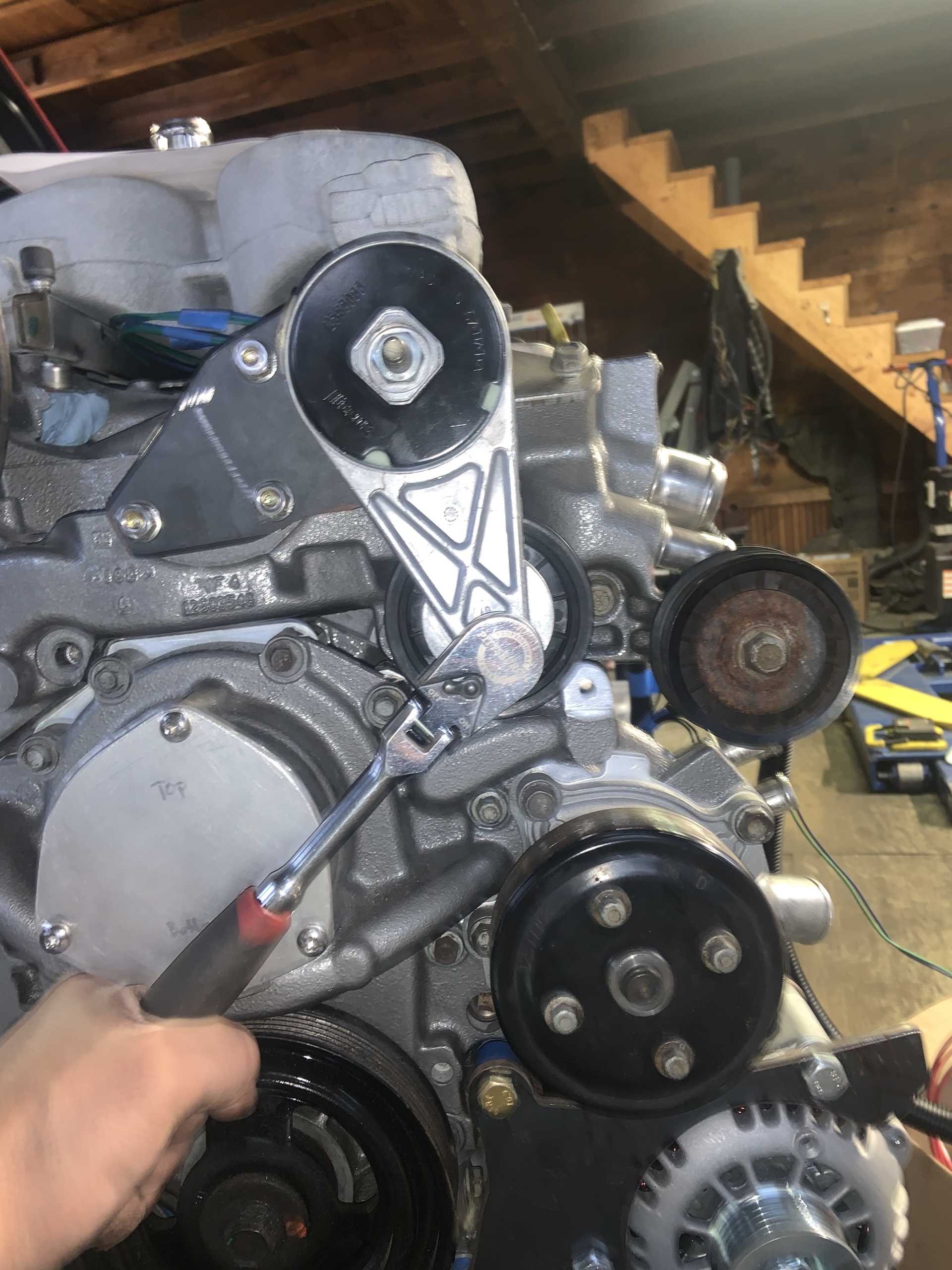
Here is an edited image of above, the green lines are showing the tangencies of the belts and pulleys currently, the red lines are showing how much farther the pulley can rotate and still be reducing belt length. The tangencies relative to the upper right idler pulley are the limiting factor in how much more it can tension, and the purple line depicts how much farther the tensioner can still rotate and be useful. In other words, clocking the pulley slightly should give me no issues with not having enough tensioning.
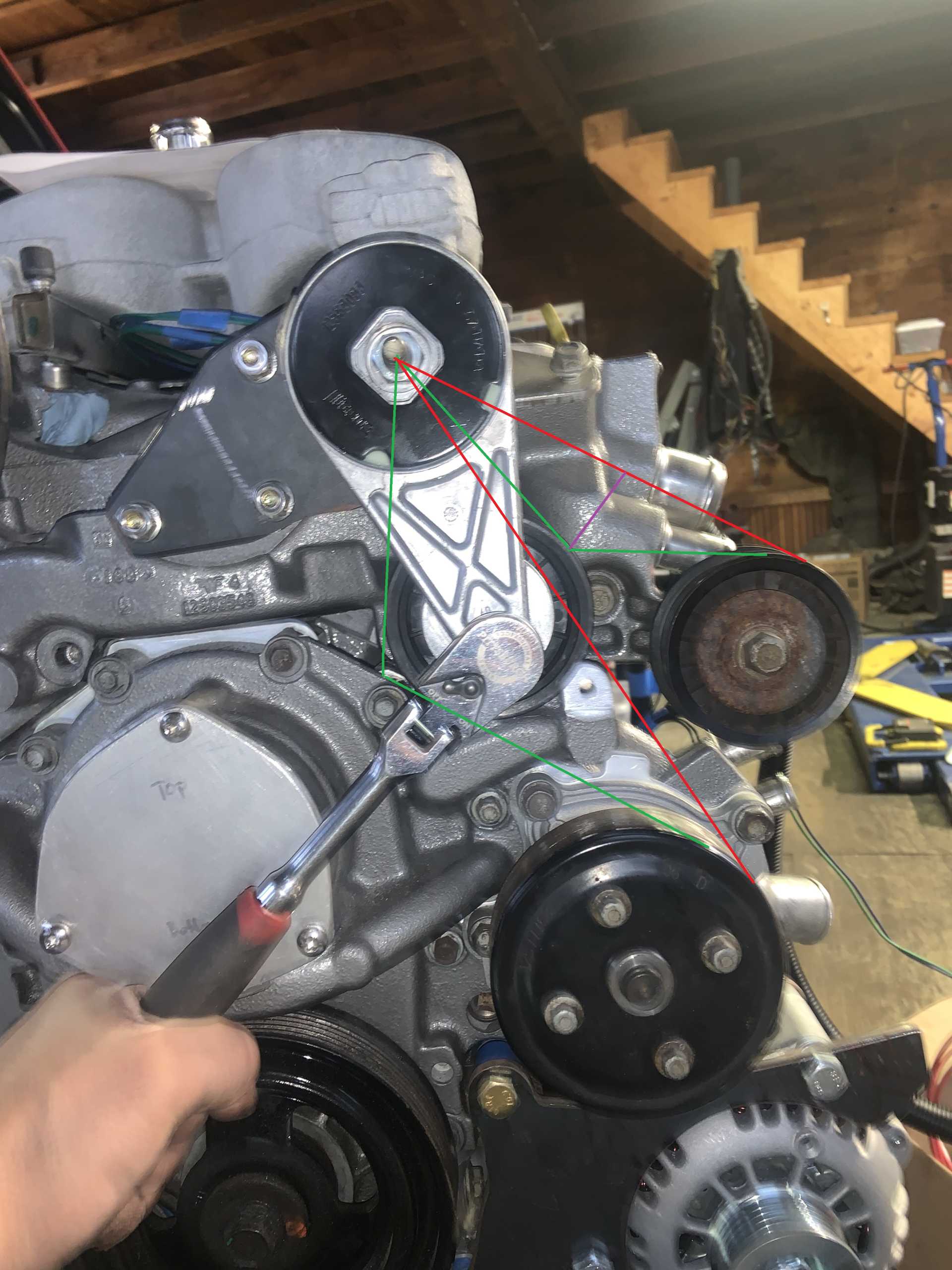
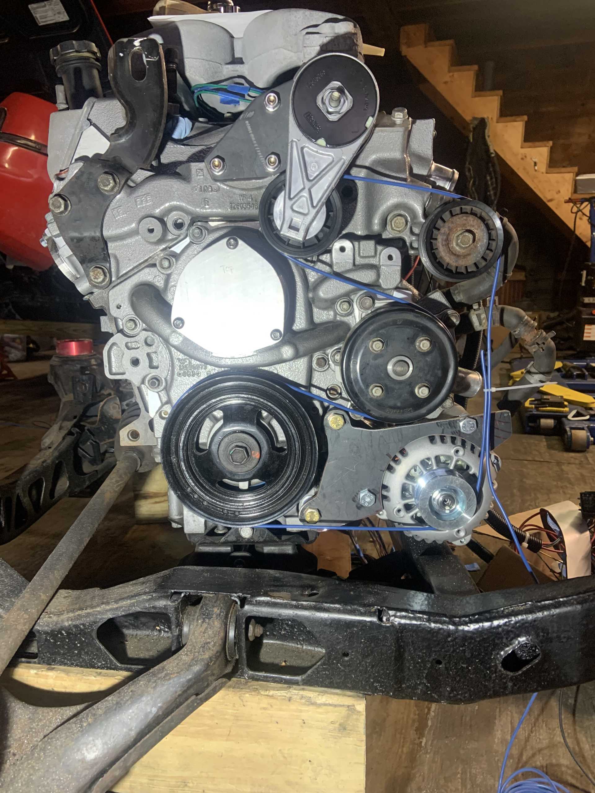
Belt routing.
I could still fill the coolant with where everything is
But I think I am going to make a new fill where I will weld some SS tubing to the plate and then the bung to the tubing to get it in an accessible location.
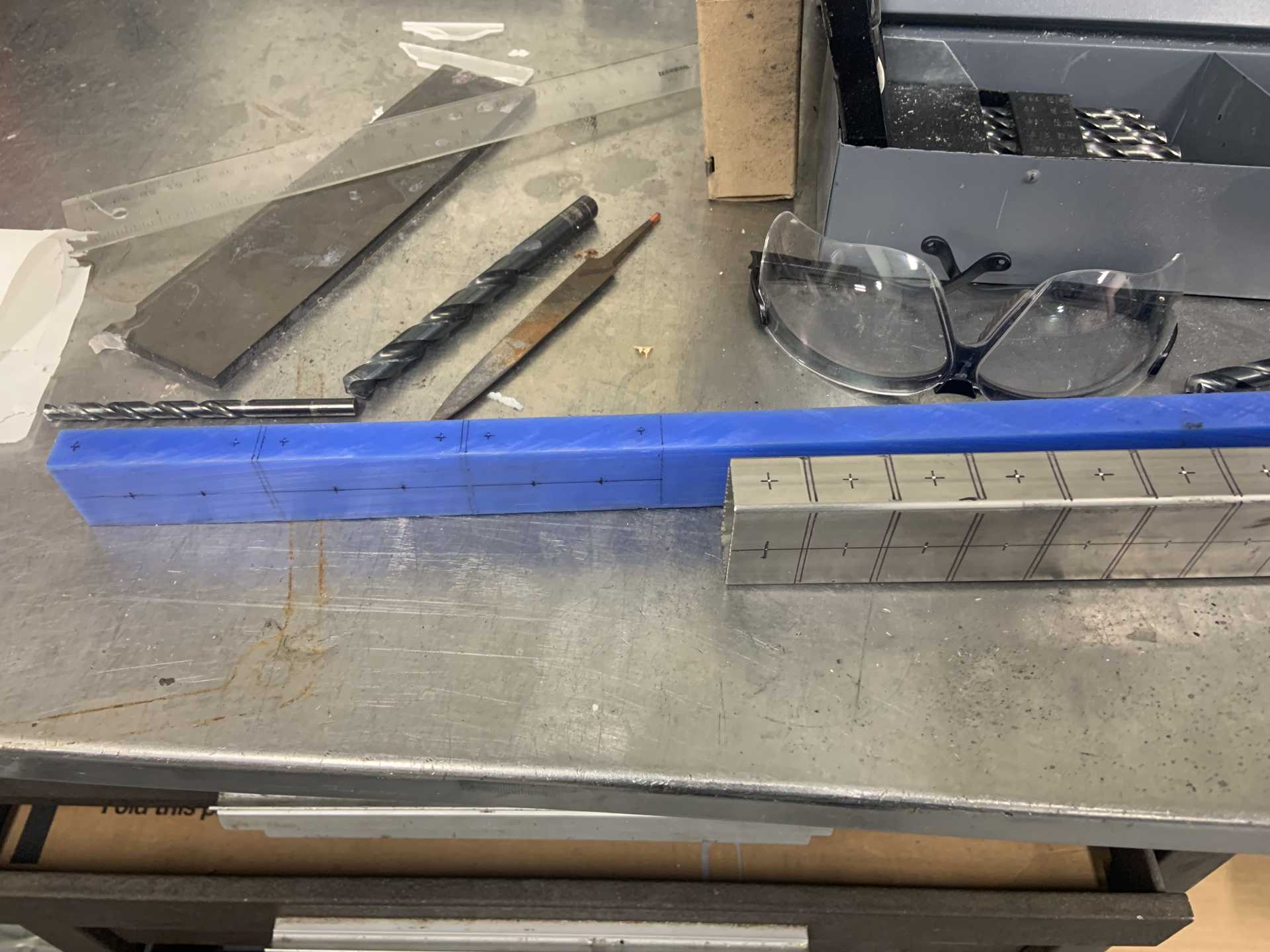
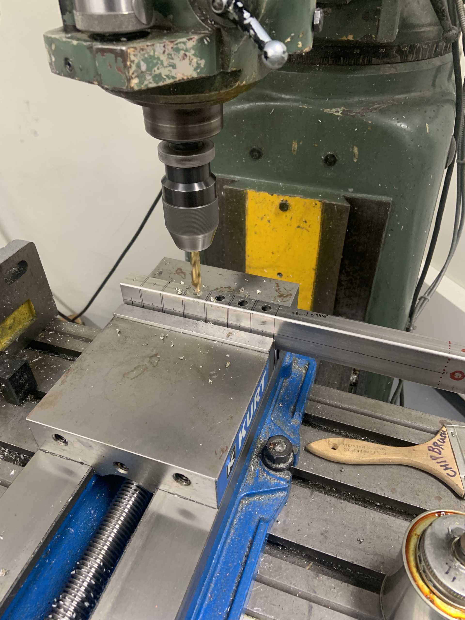
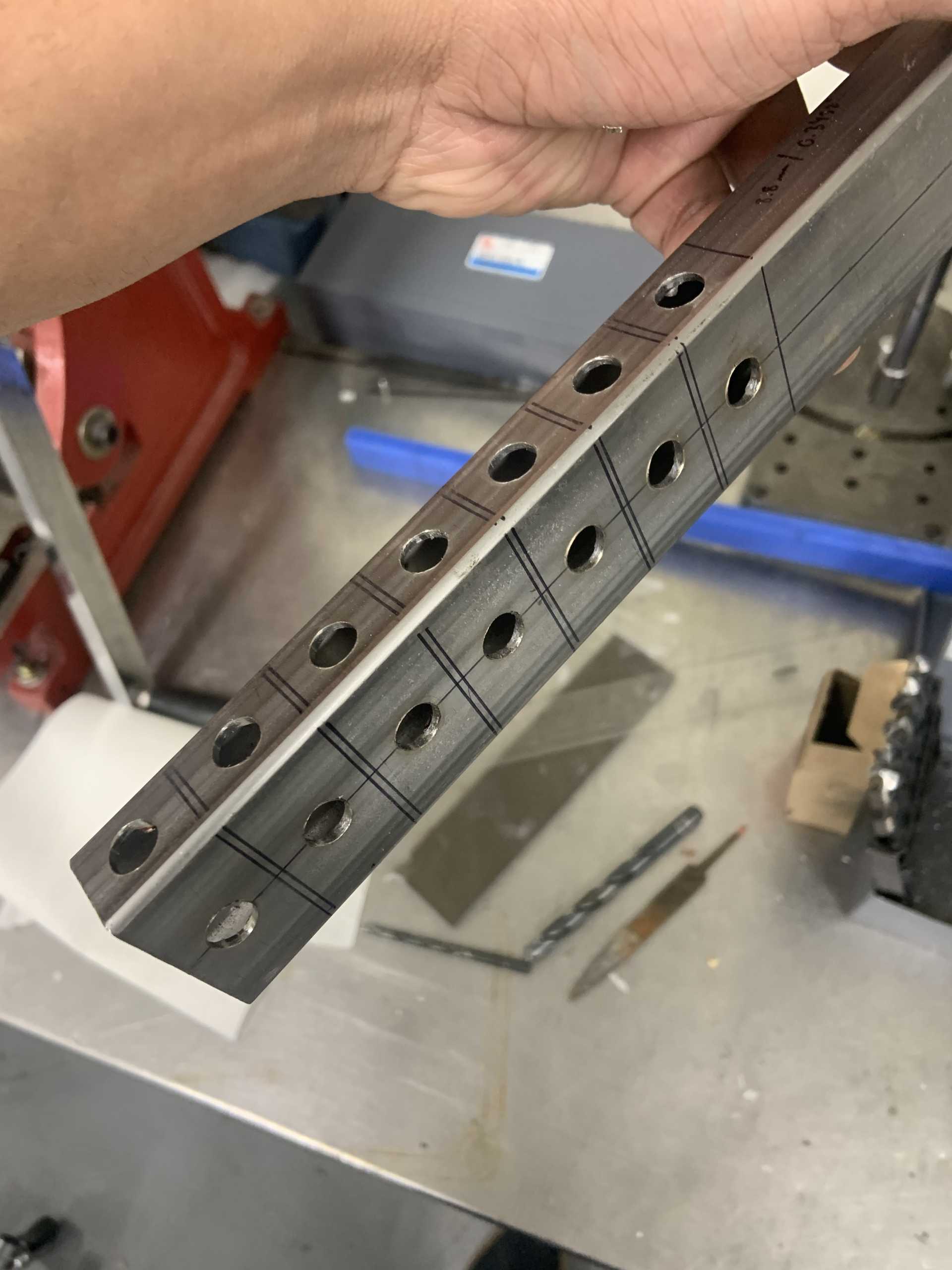
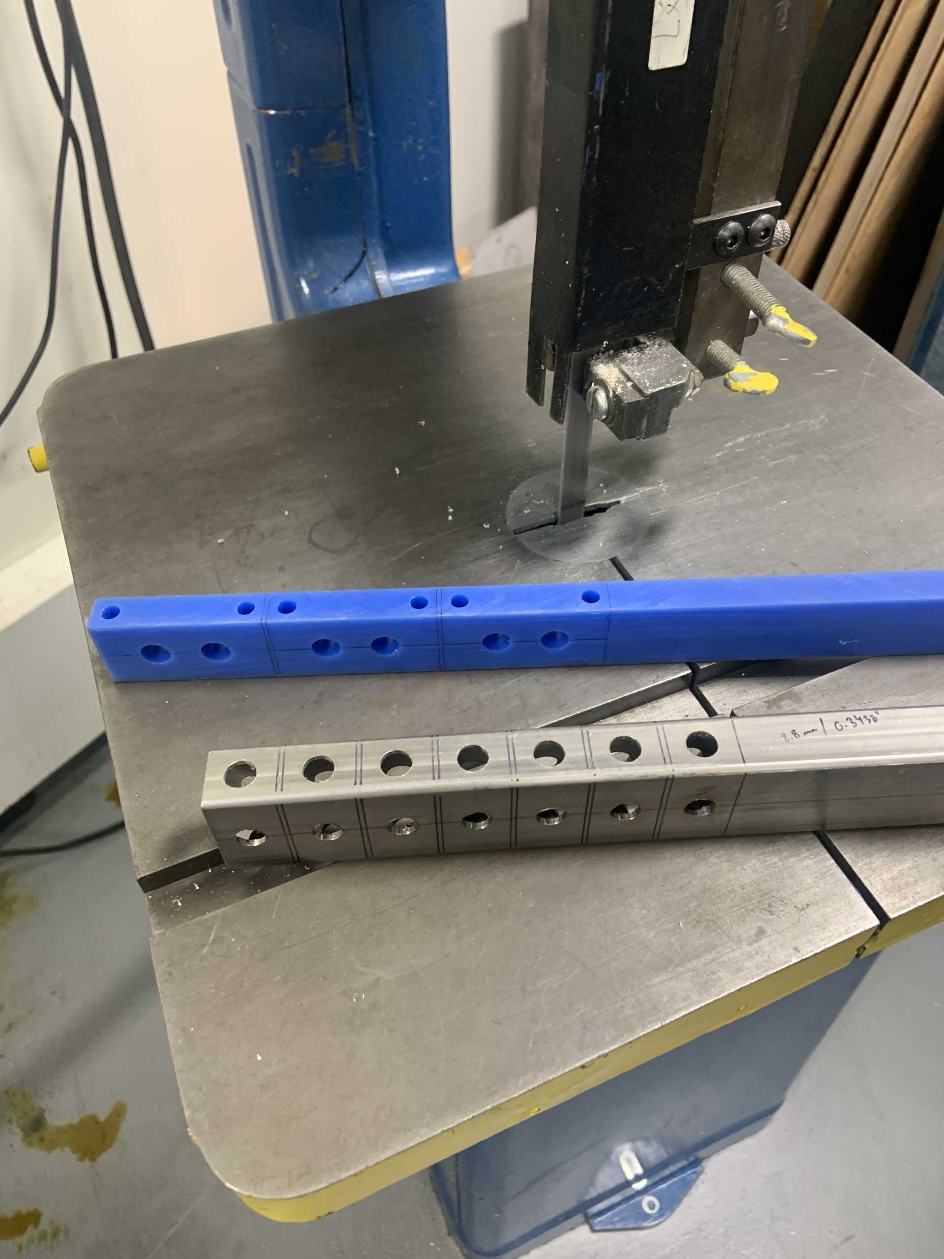
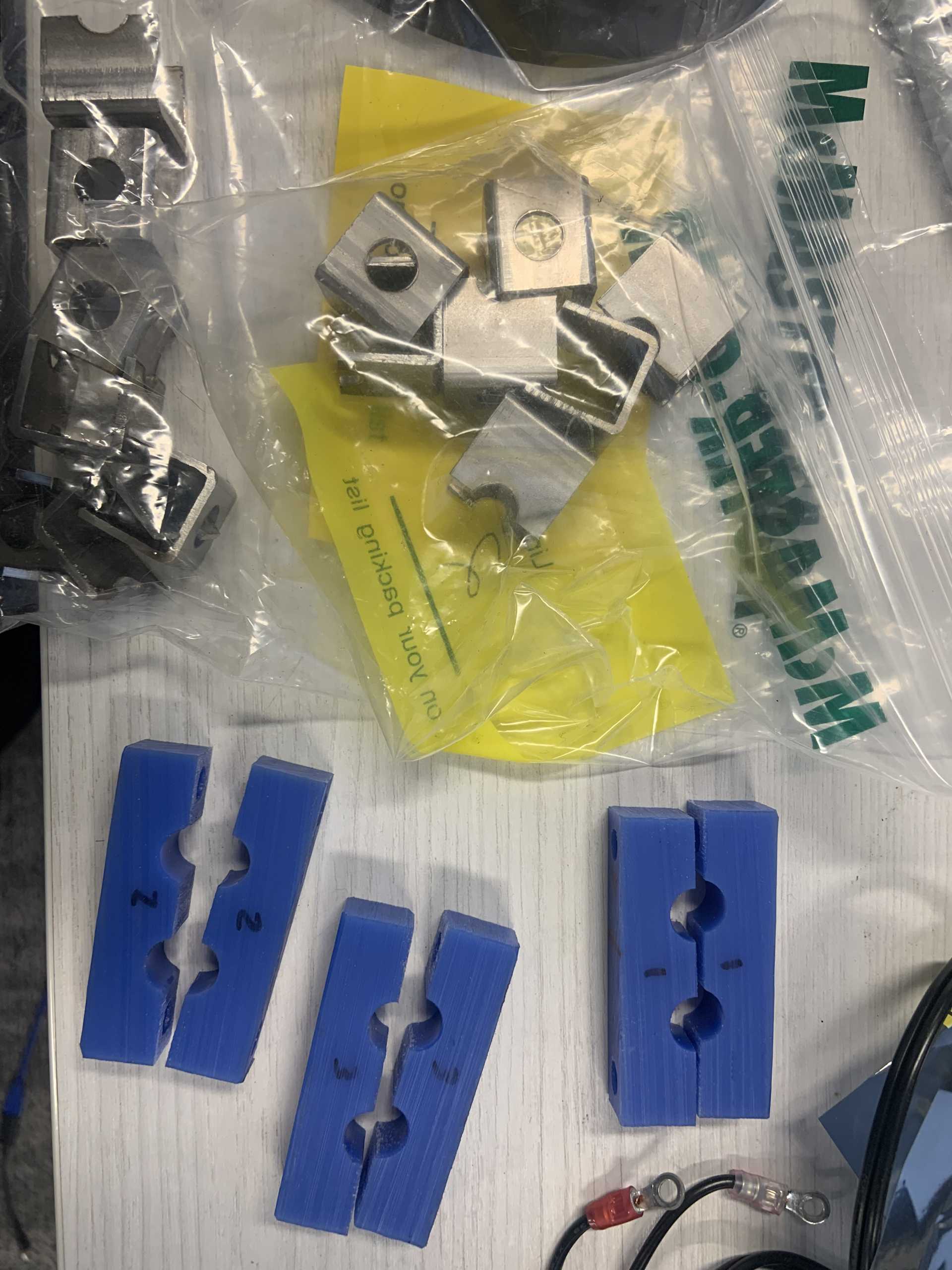
I also made some brackets out of SS to weld into the engine bay, they are sized to accept a press fit M6 nut. I made some fuel line clamps out of high temp plastic too, I drilled holes for the lines and then when they are cut in half with the band saw it creates the clearance to clamp down on the lines.
Parts have been coming in, I am on a roll.[This message has been edited by zkhennings (edited 02-18-2023).]
|
|
|
|
zkhennings
|
MAR 14, 09:52 PM
|
|
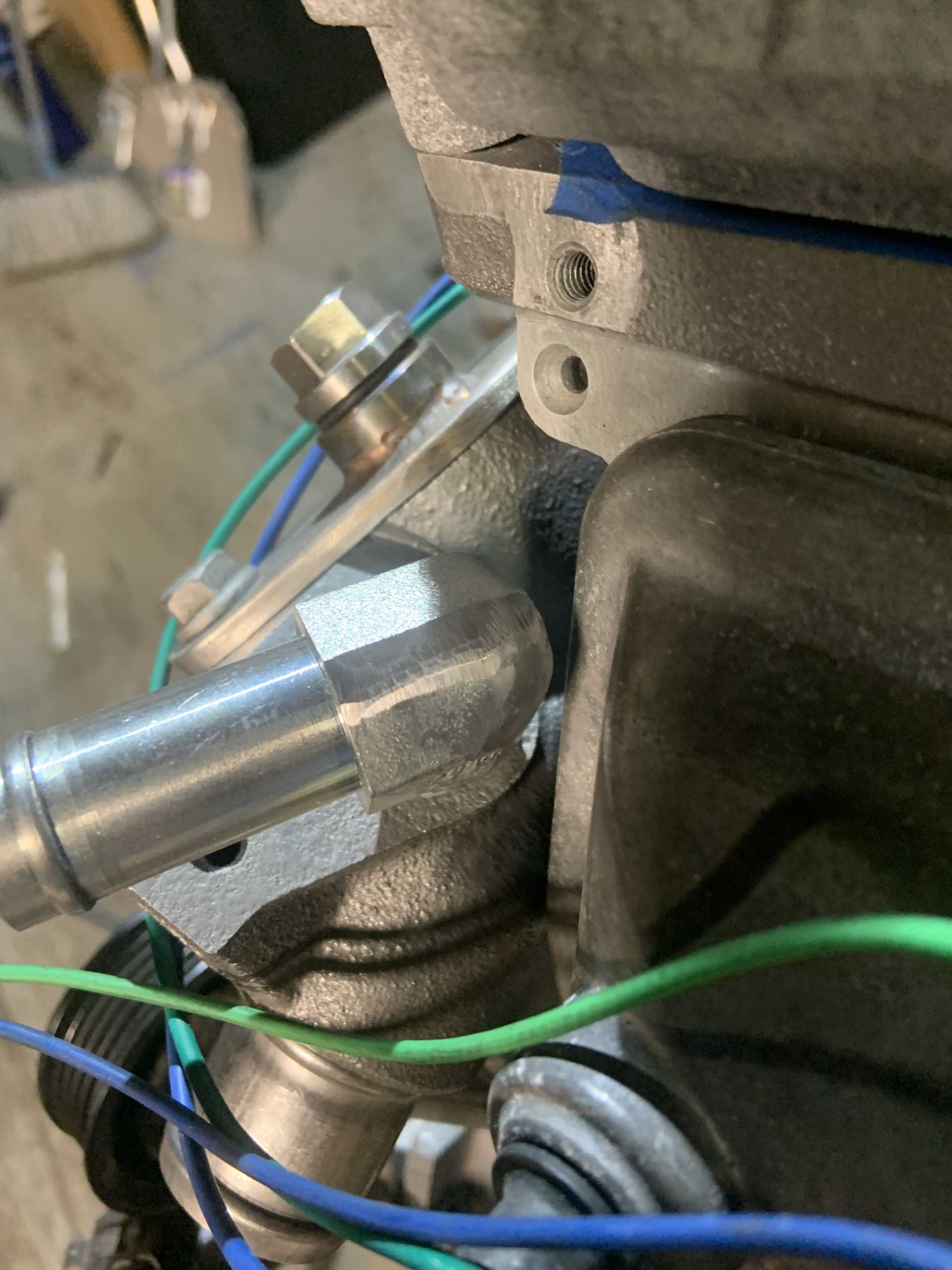
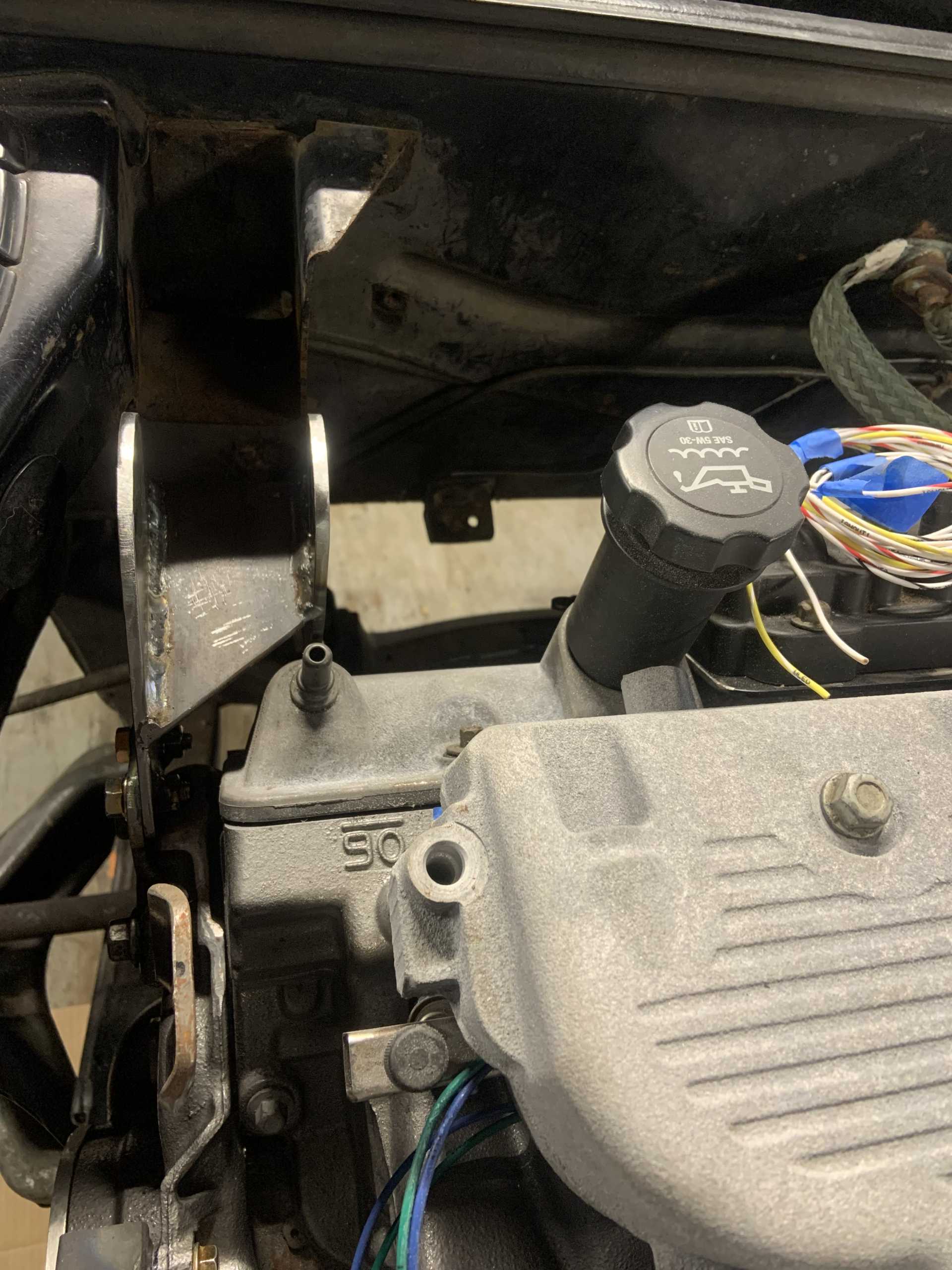
Tapped the heater outlet for 1/2" NPT, did not need to be drilled out or anything.
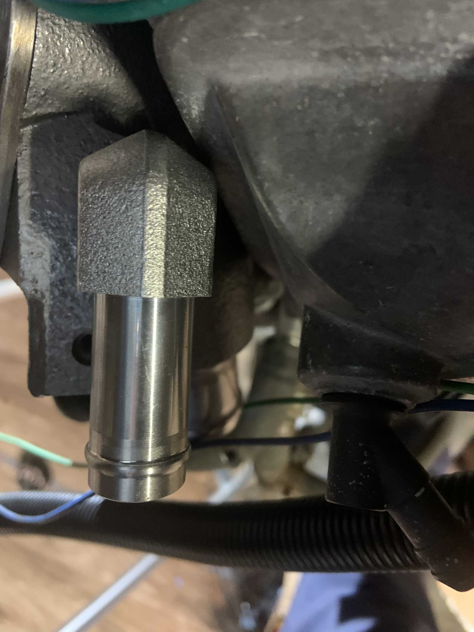
It was close to the valve cover so I cleaned it up. It probably could return to parallel and still clear fine. I just want to be able to pull the valve cover without much fuss.
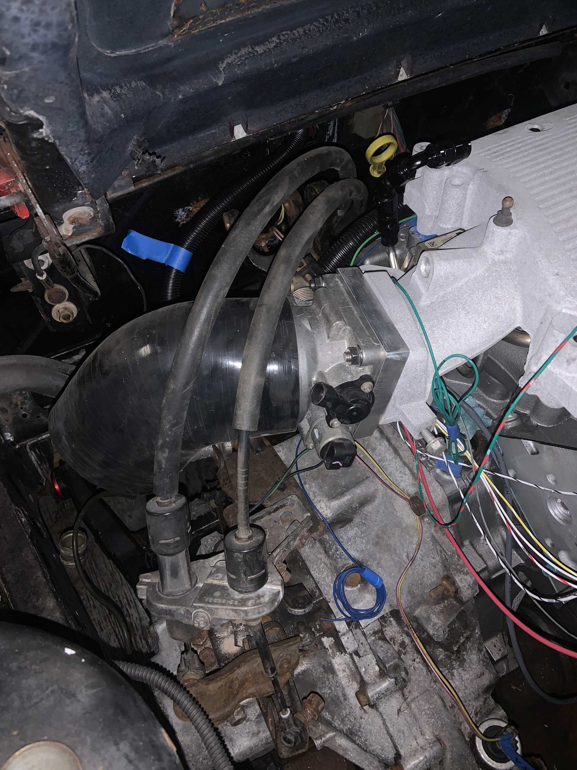
I checked out having the TB upside down and learned it will interfere with the shift cables. So original orientation it is. Going to need an offset reducer and go down to 3" tubing as the shift cables are a little too tight to the 4" elbow.
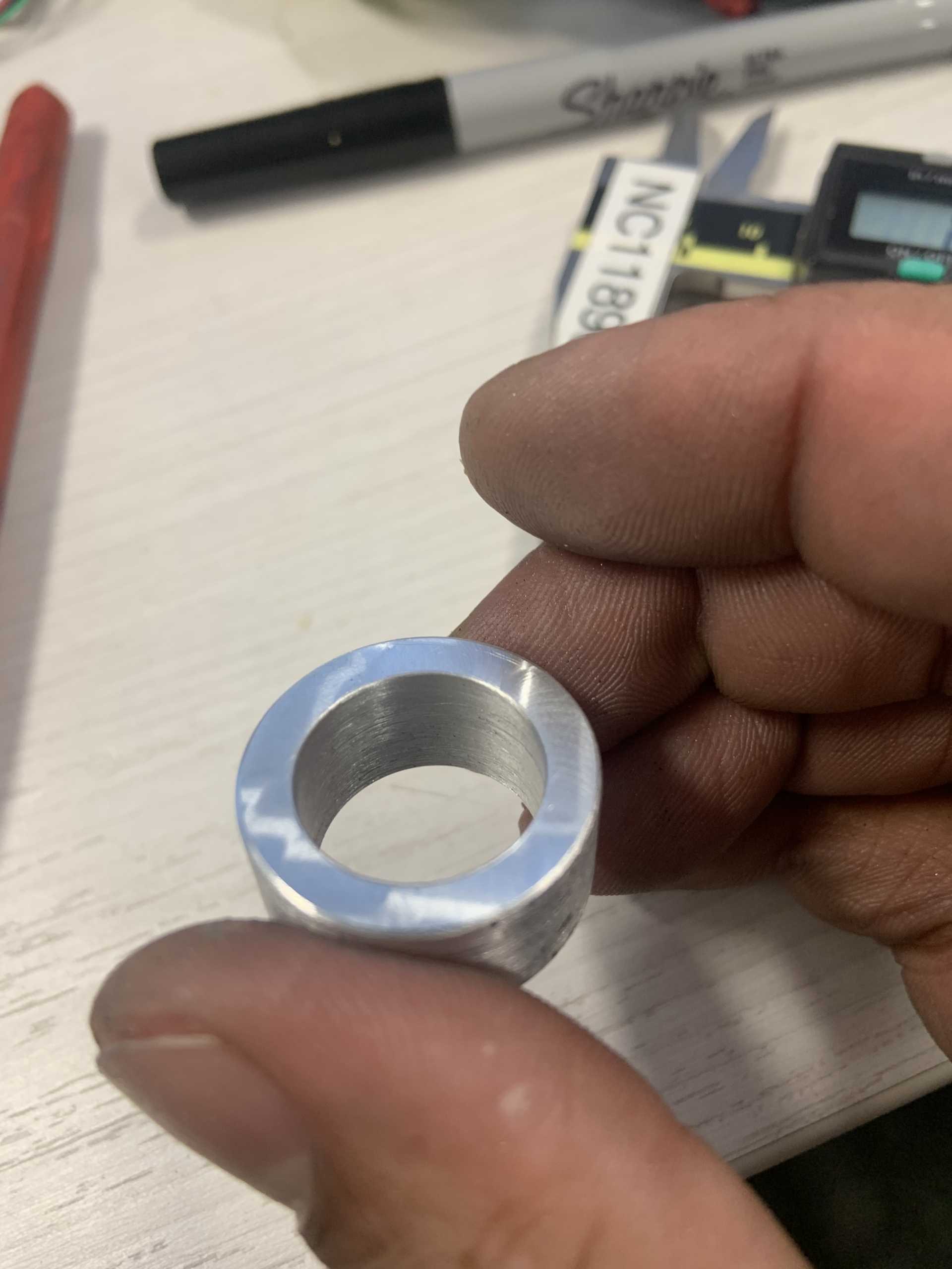
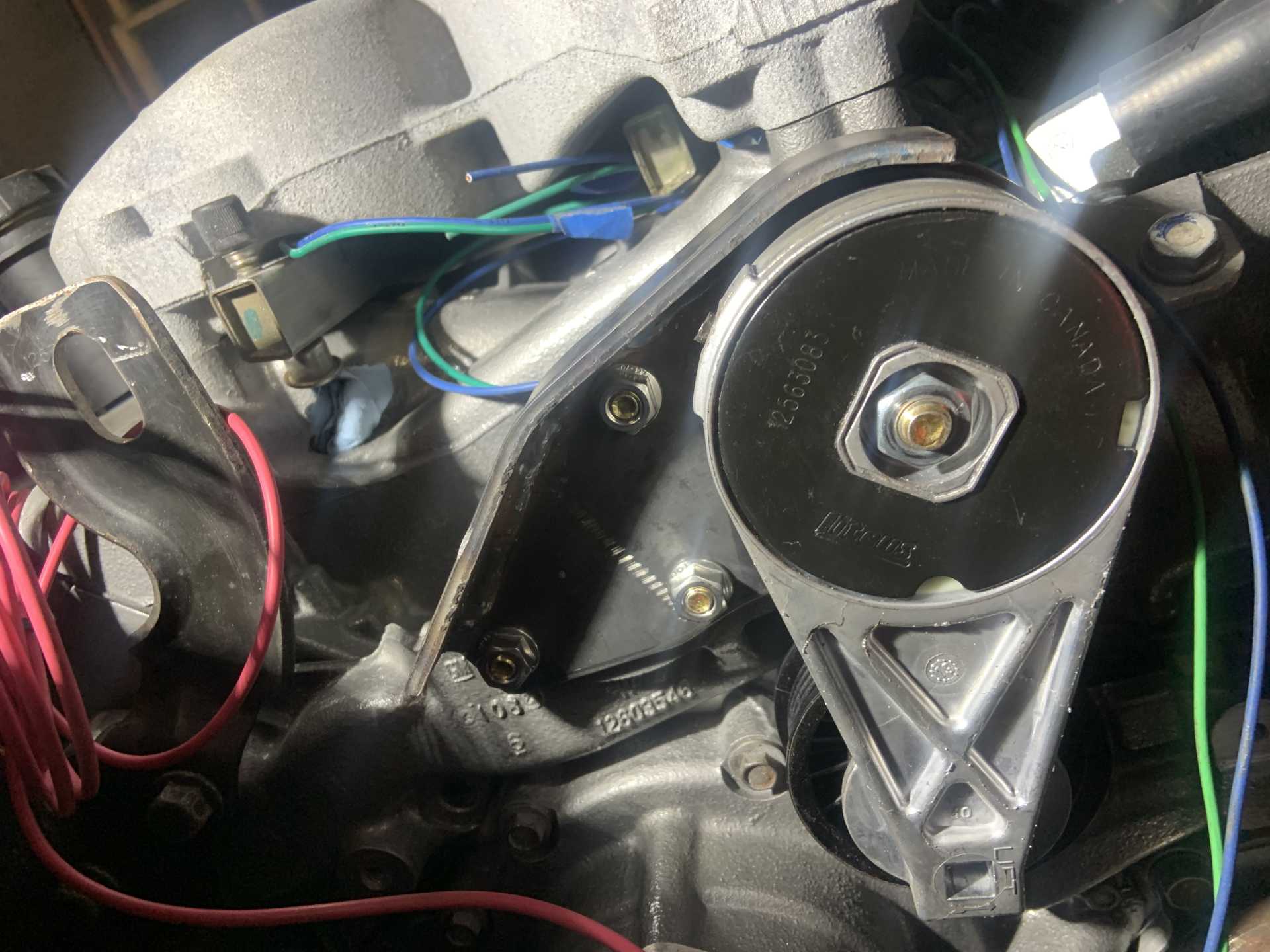
3D printed a centering bushing for the tensioner pulley.
Made an aluminum spacer for the tensioner pulley.
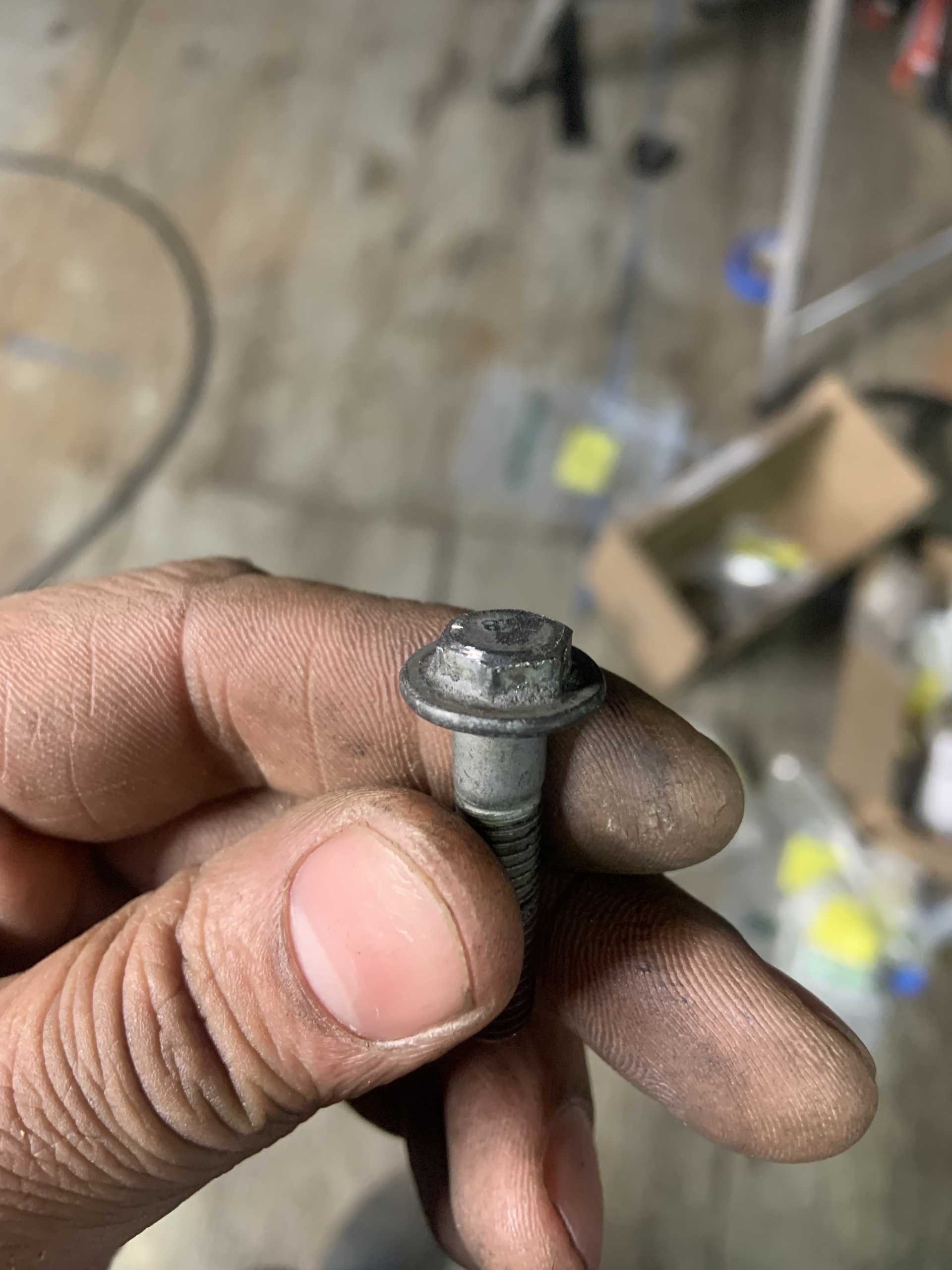
Trimmed an offending bolt head down.
Fit check.
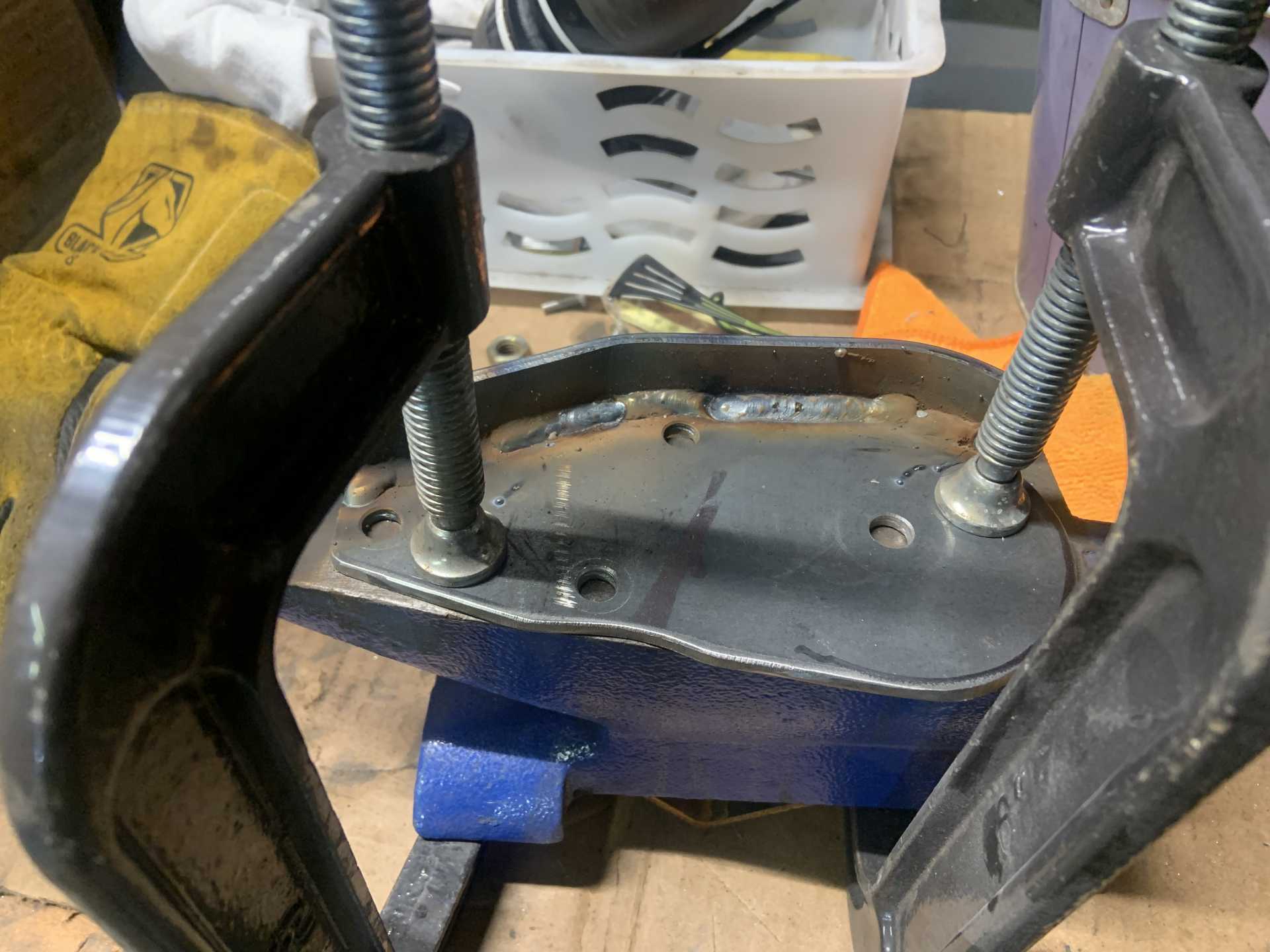
Welded a stiffening rib to keep the tensioner bracket from flexing.
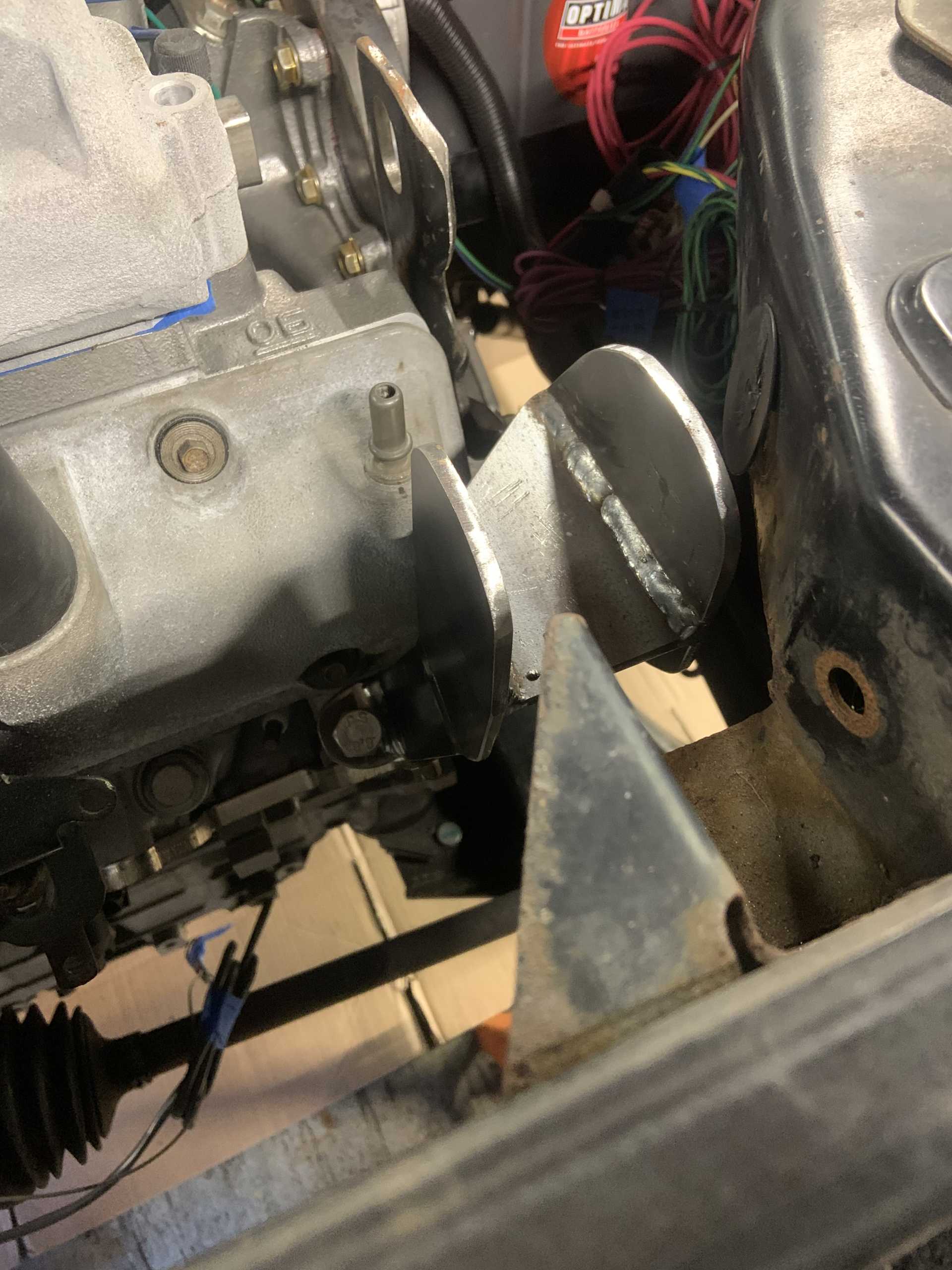
Dogbone CAD while engine is still in the car.
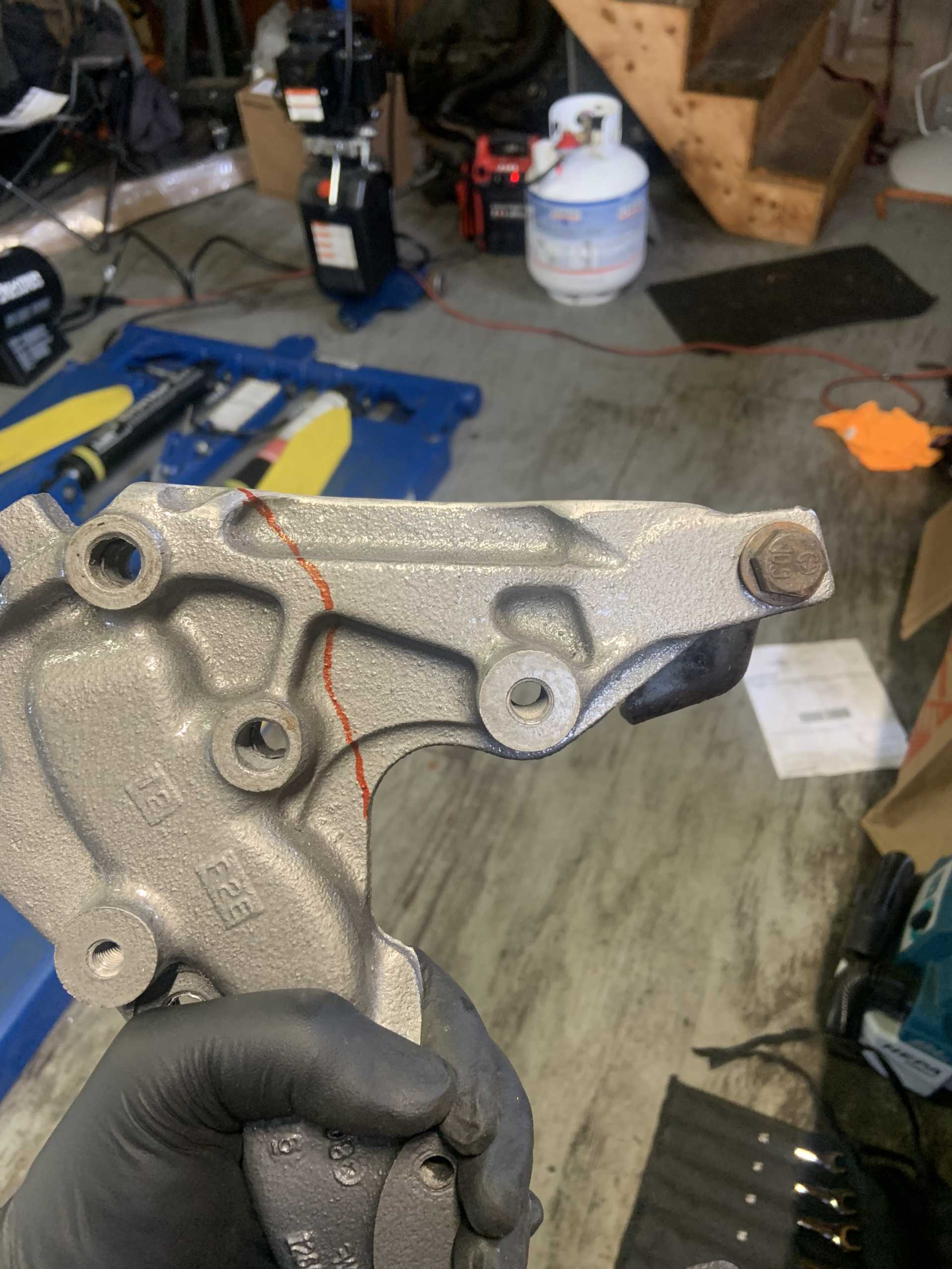
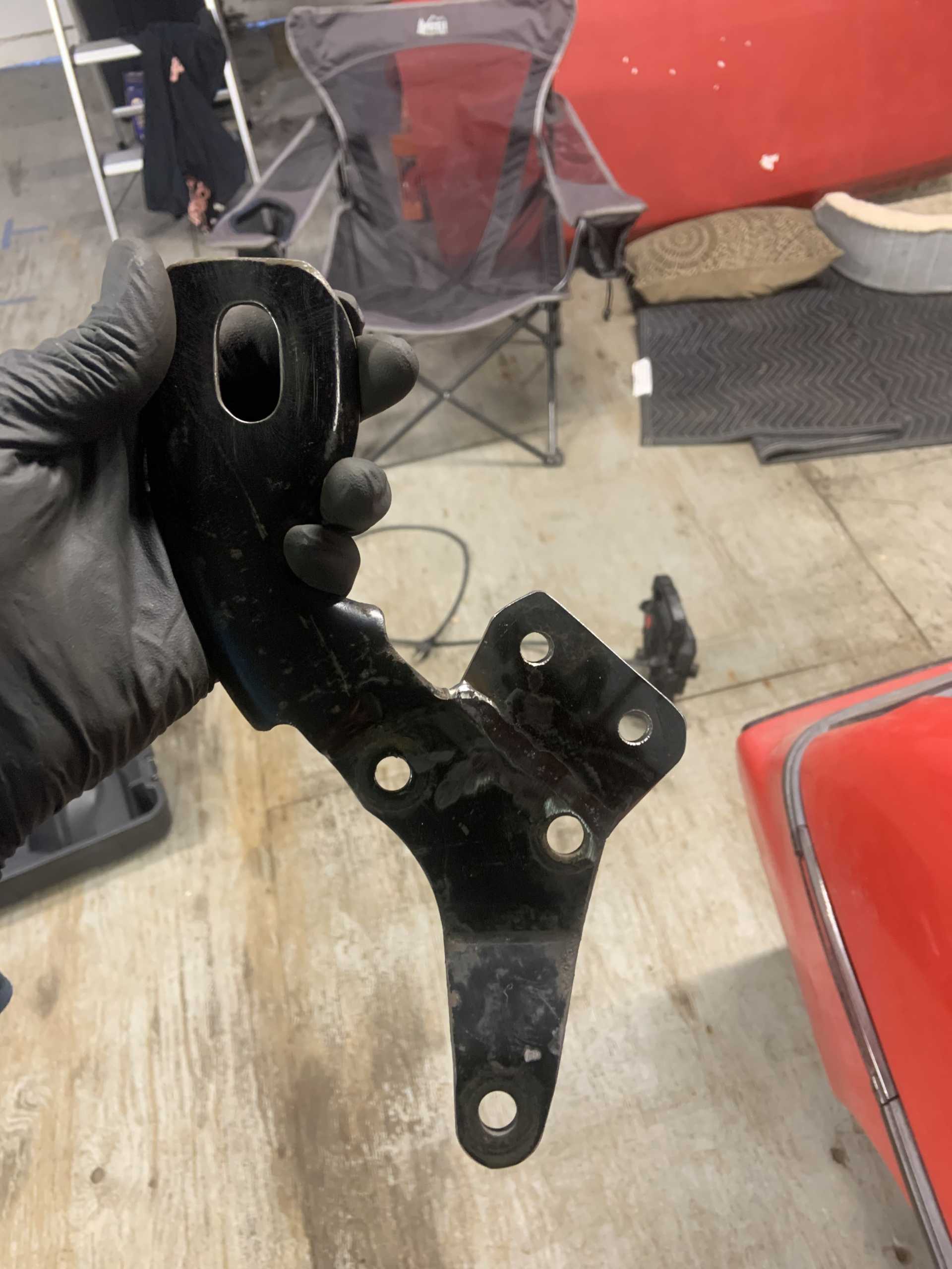
Decided to make it easily removable by adding a bracket to the lift bracket.
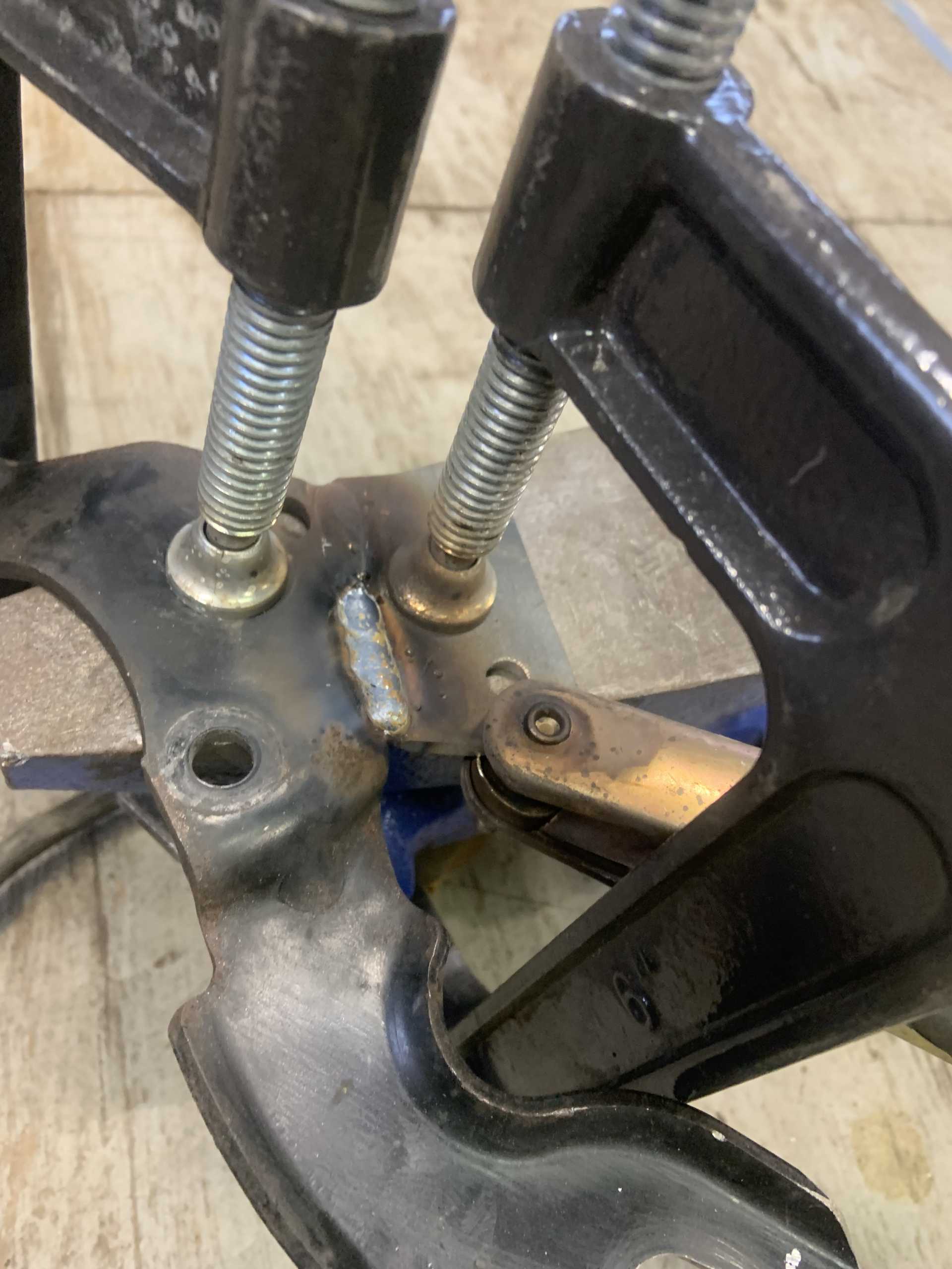
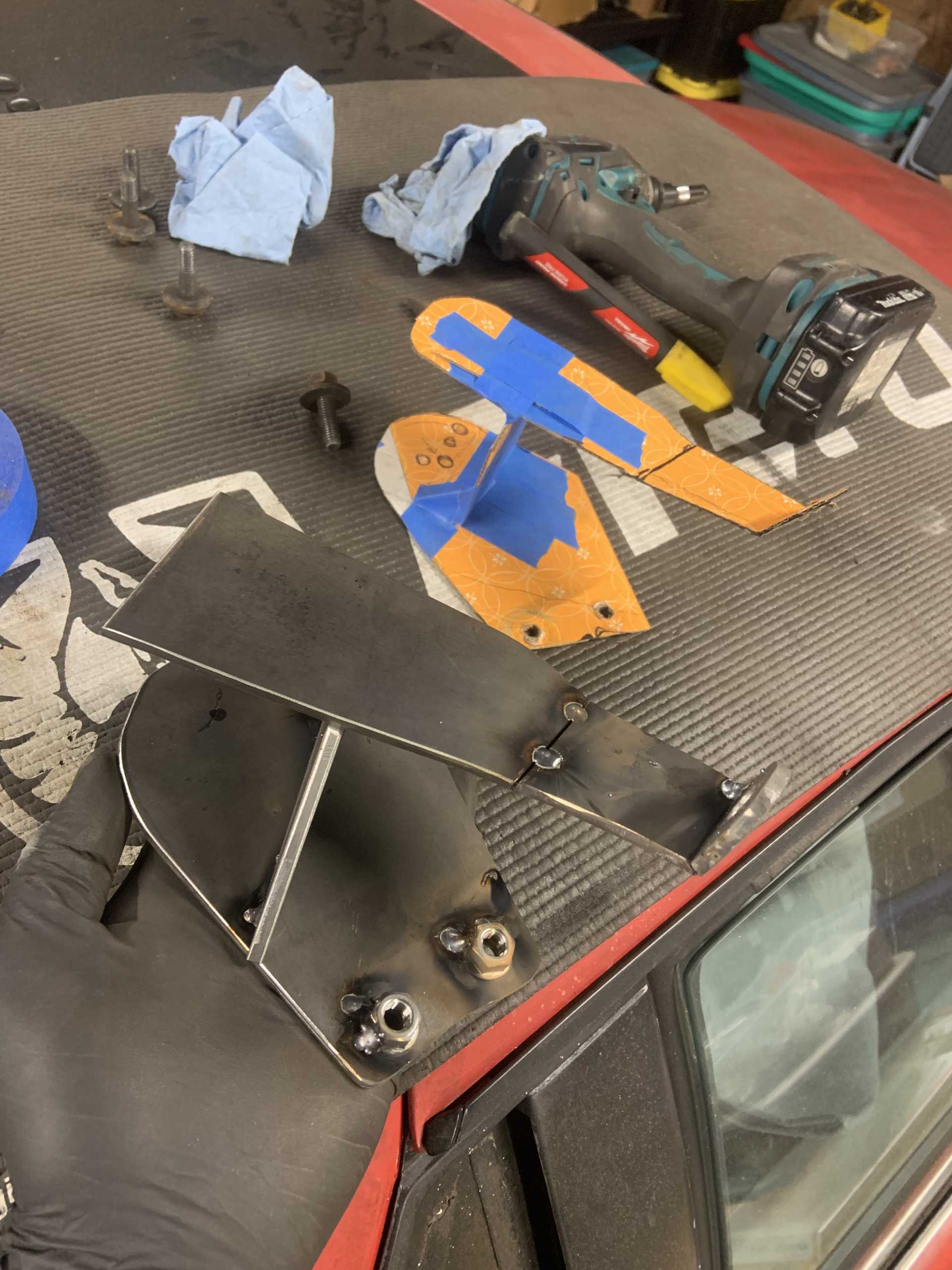
I made slices where I bent the 3/16 sheet metal to make it bend precisely. Welded those up.
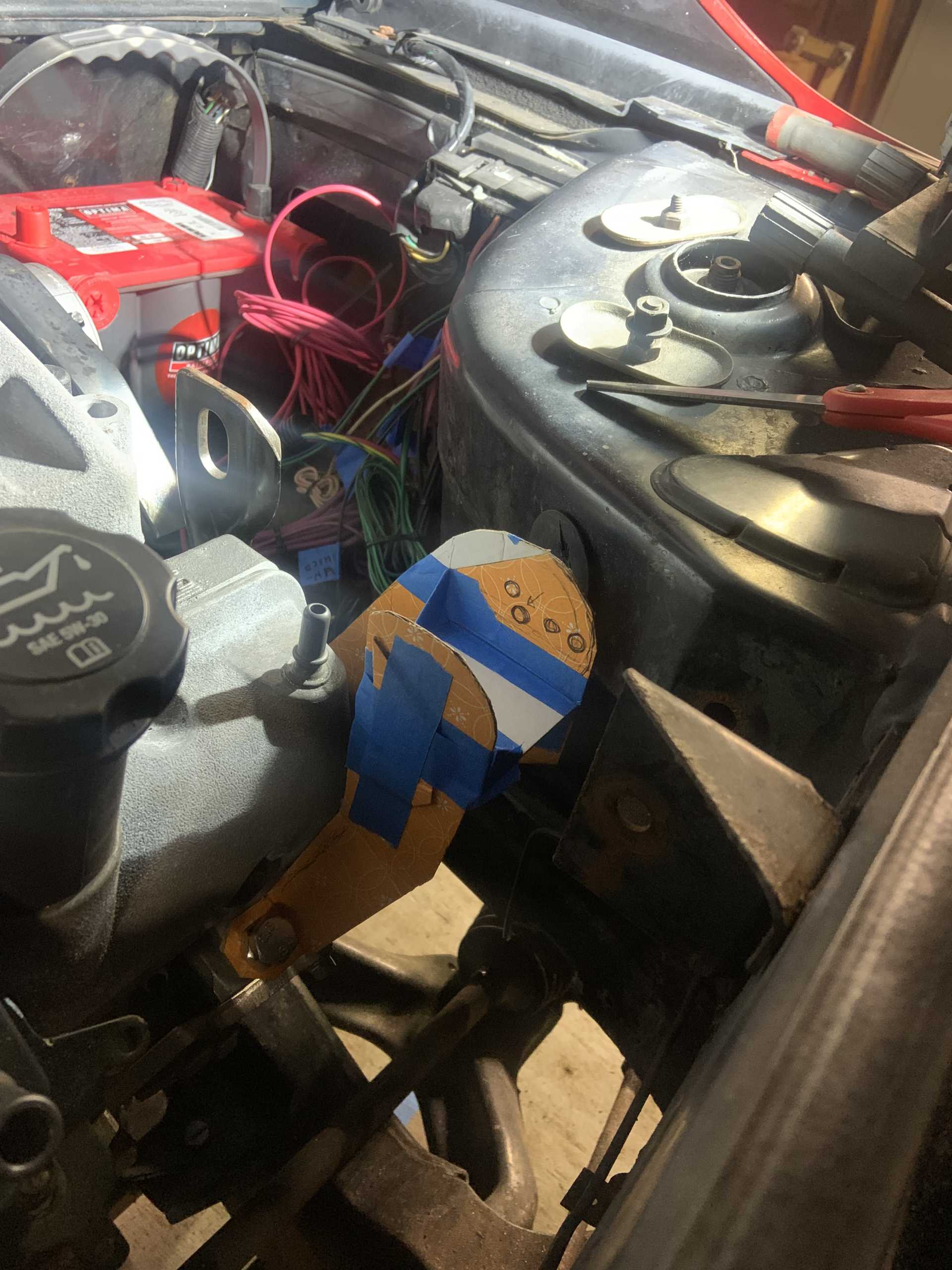
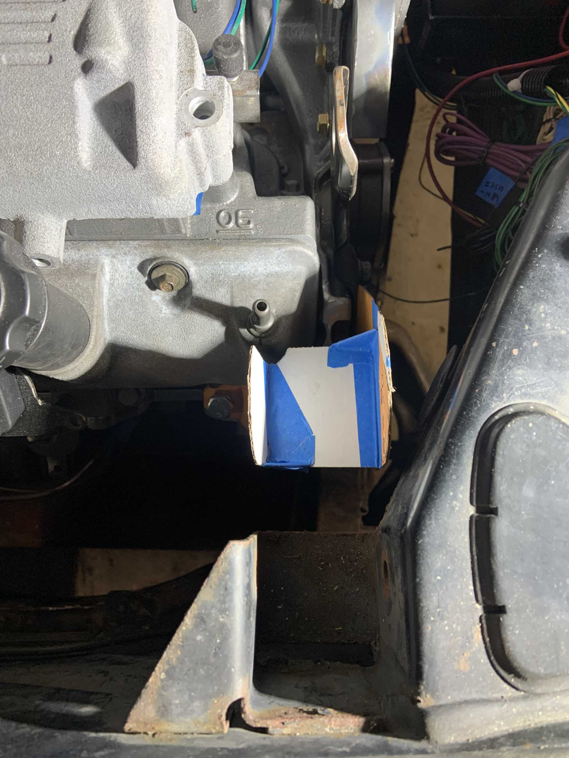
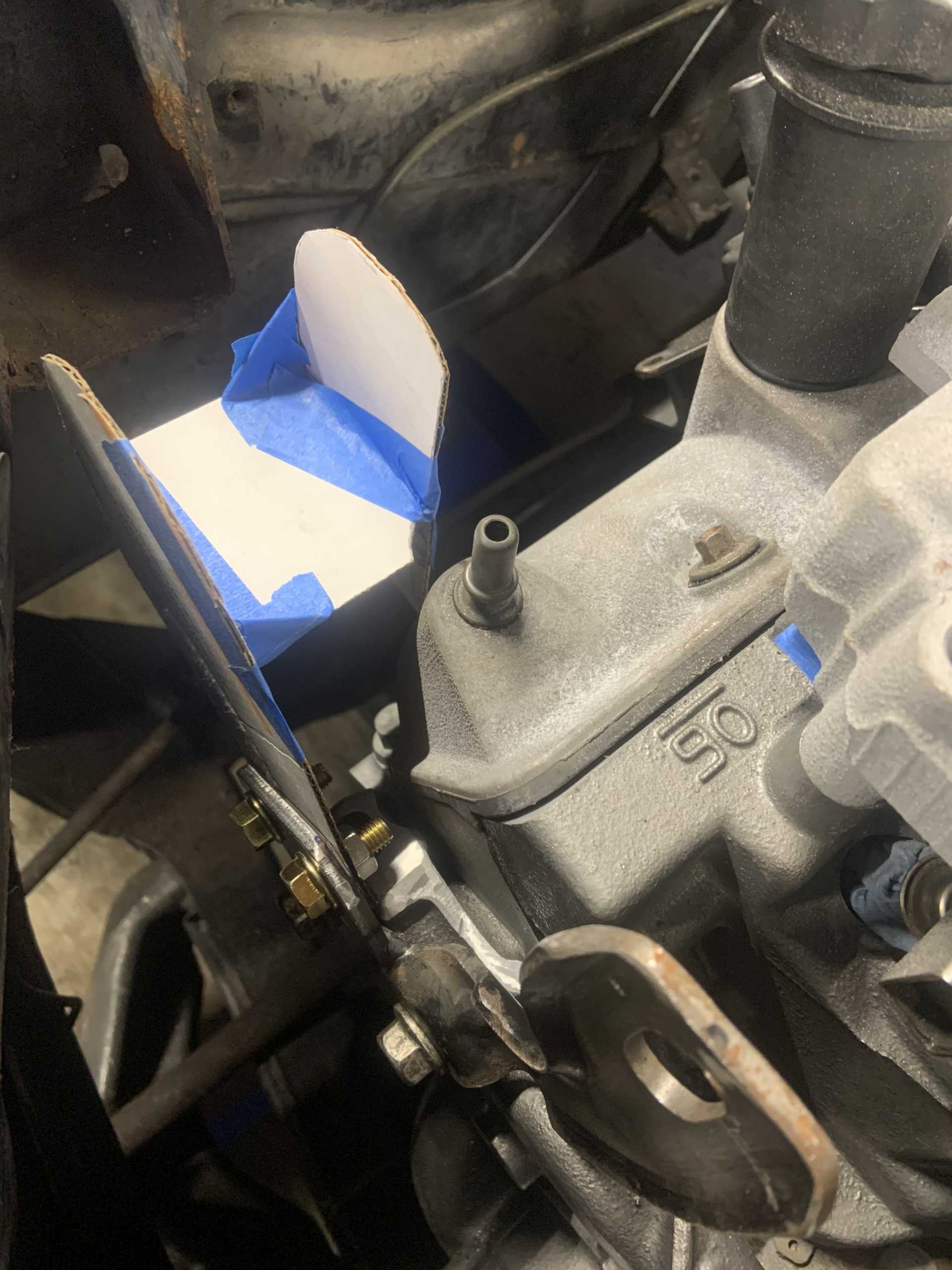
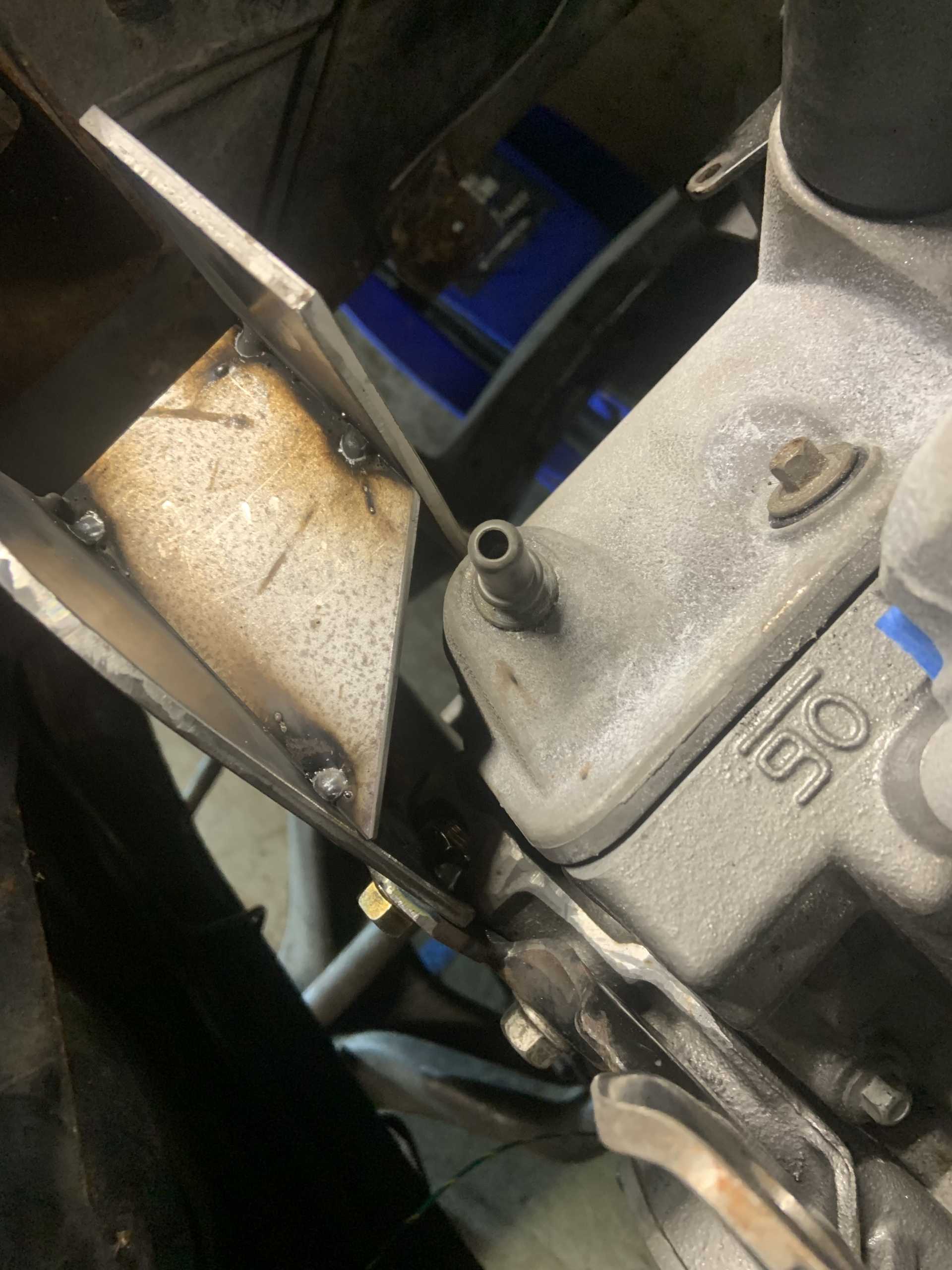
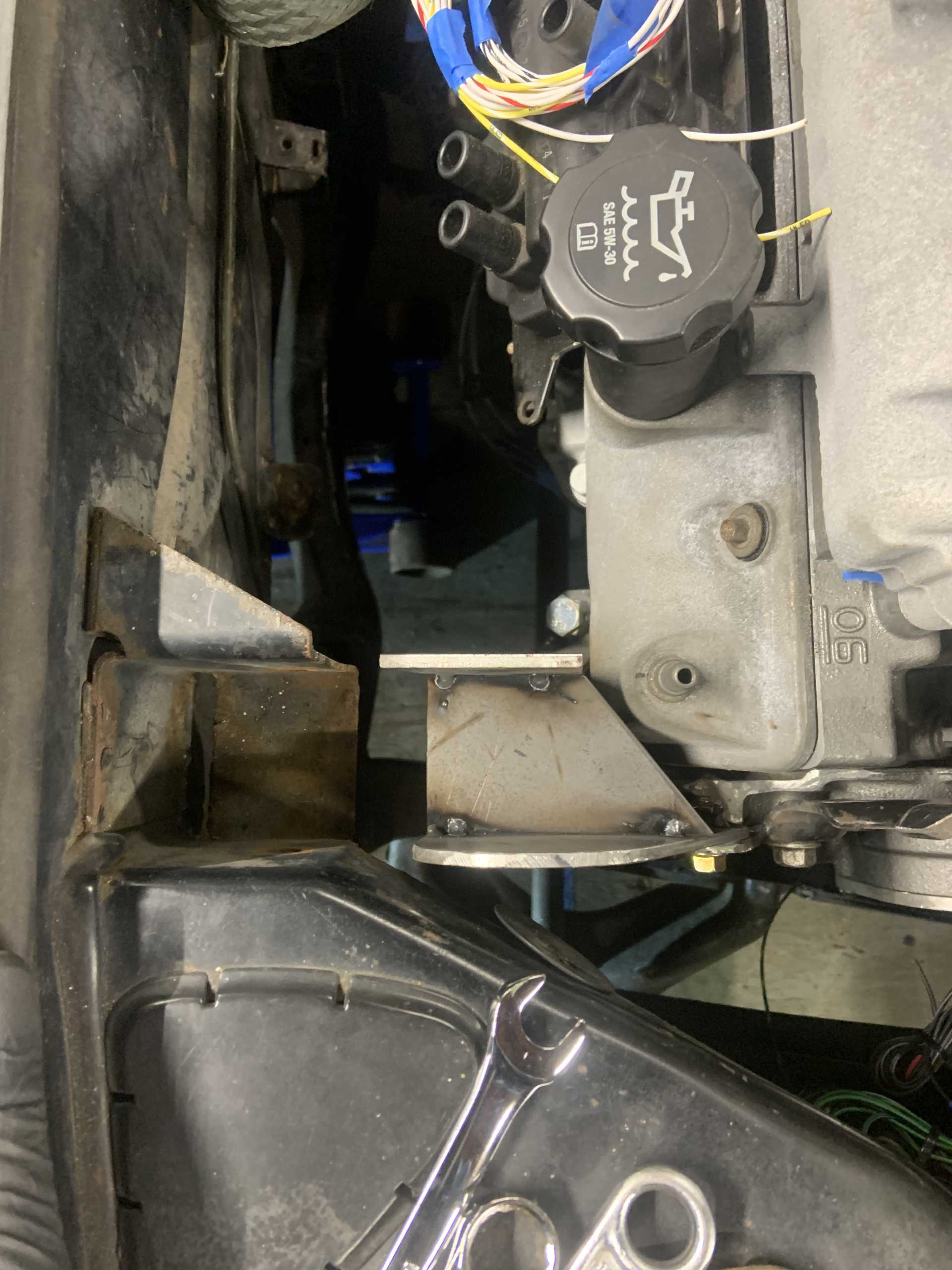
I have been working on the header design and mock up. Here are my mock ups. I used them to determine what angle the collector needs to be at relative to the block.
Here they are on the motor.
The firewall side header needed to be removed before I could adjust the collector angle properly.
Starting the final tasks before it is ready to go back in for the last time.
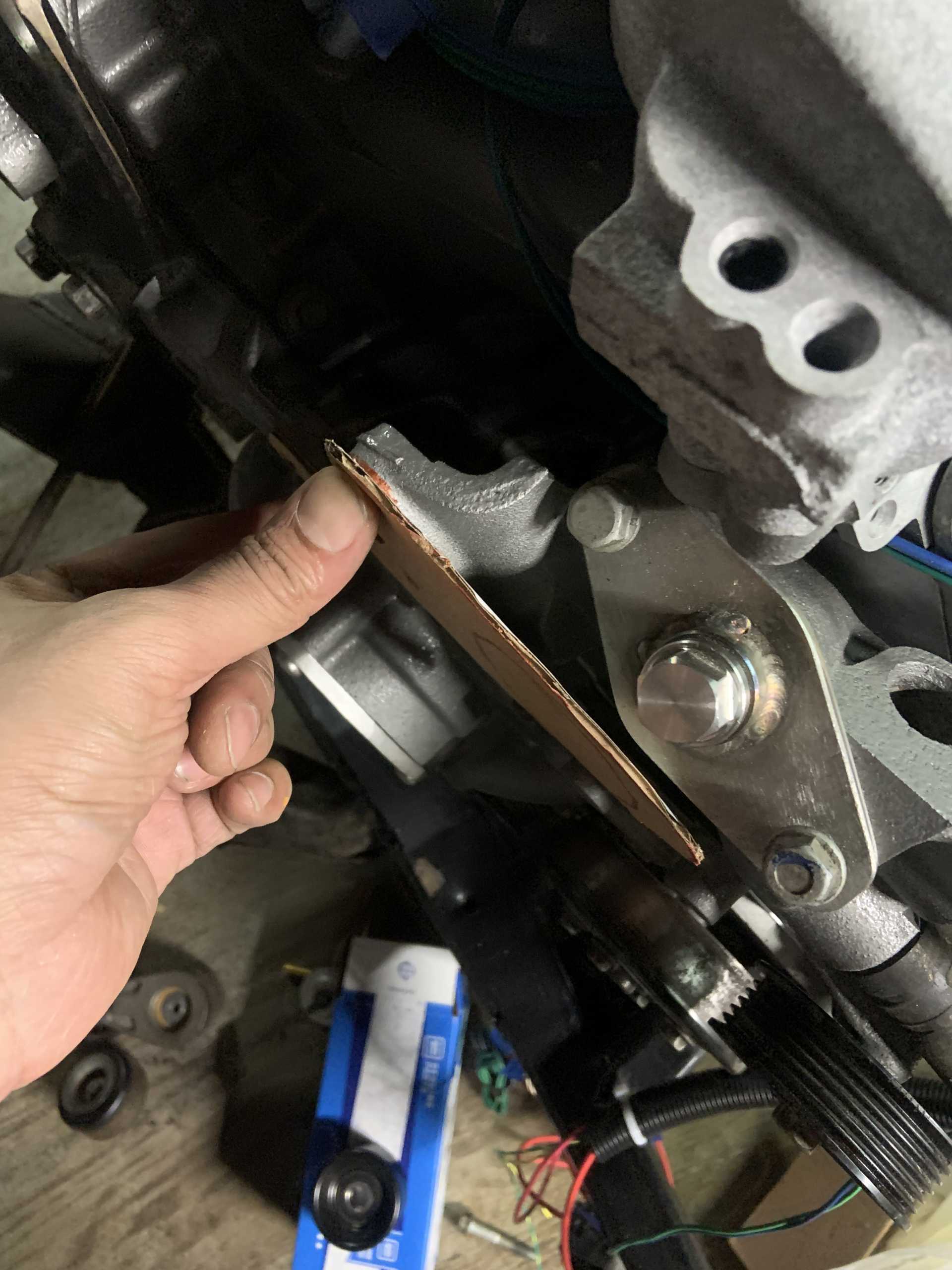
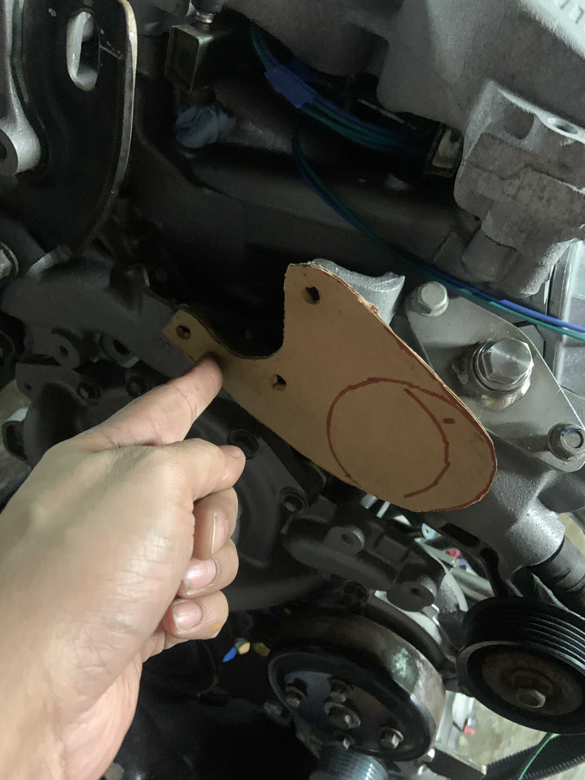
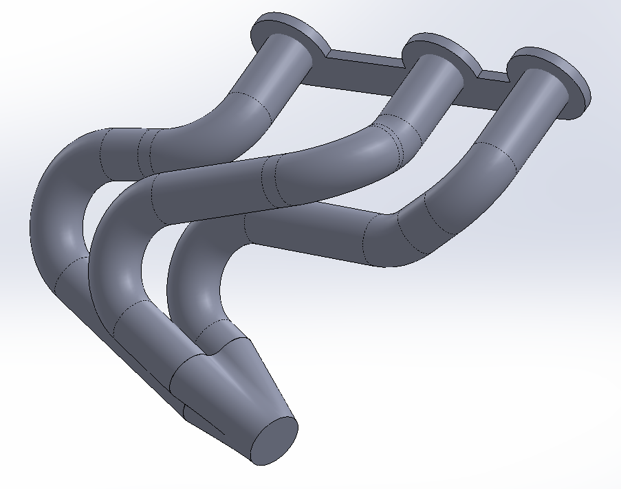
Finalizing the CAD for the headers, I will make a cardboard outline form for final test fit before making them. I have been able to make them equal length in the CAD, they are 22" primaries. Not as long as the 28" I hoped, but it is a good compromise of all things considered.
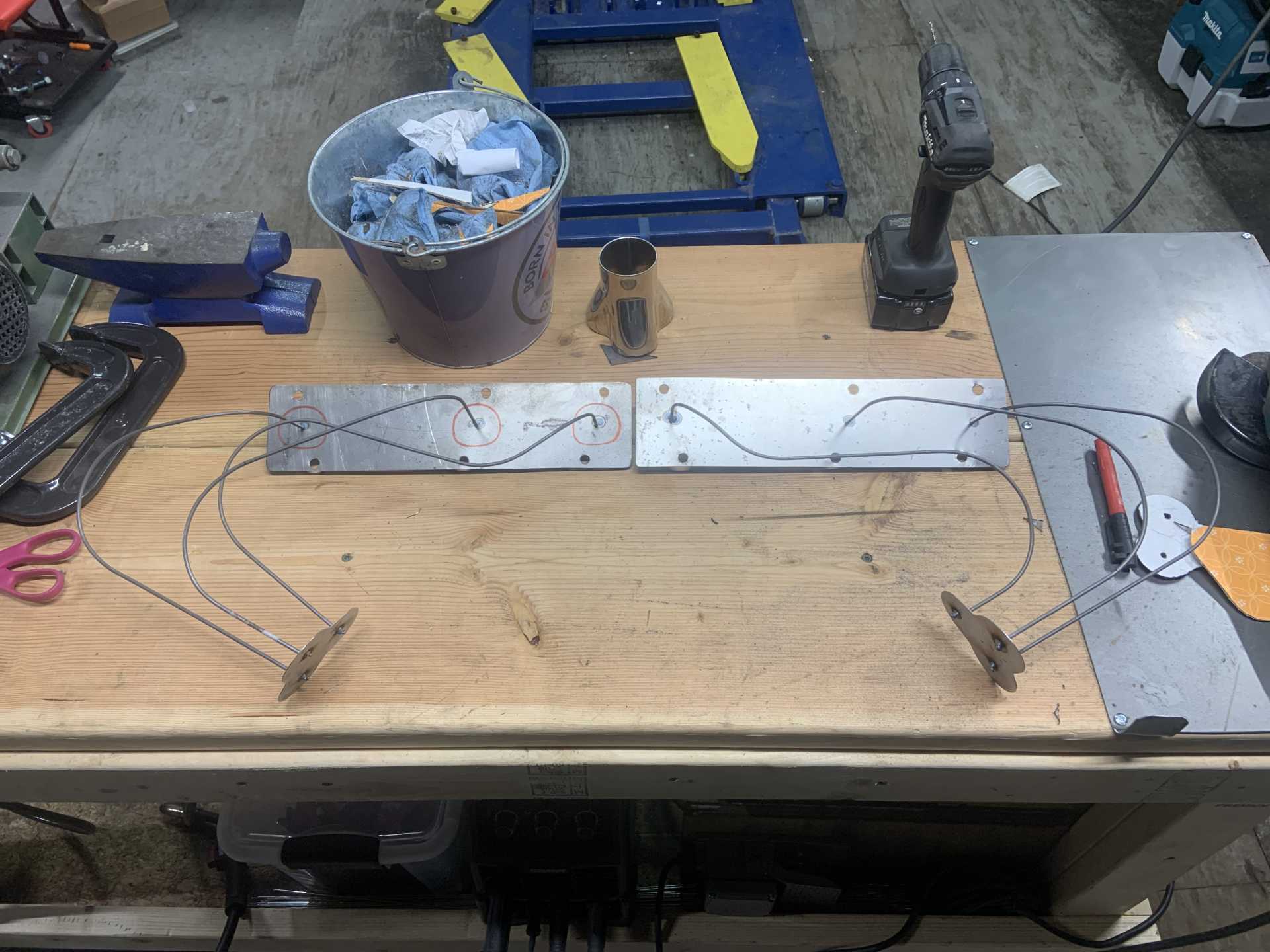
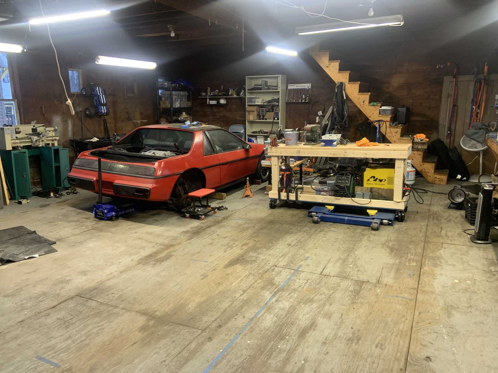
And some side things, I made a fabrication table so I can make messes near the garage door.
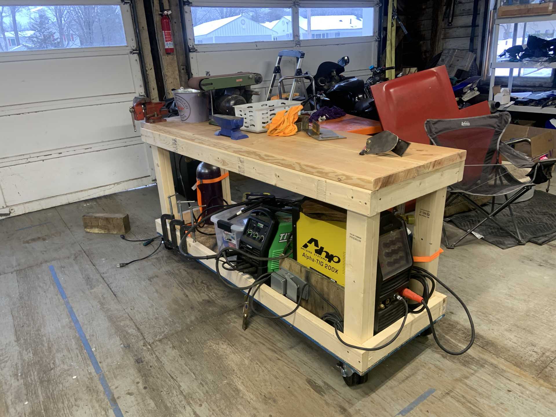
And it even fits over the lift.
|
|
|
|
zkhennings
|
APR 19, 01:50 PM
|
|
Took a mini haitus to go on vacation and do some side work on a coworkers WRX, pulled the motor and did all the valve clearances, timing belt, water pump, main seals, and a new flywheel and clutch. Doing an STI now but getting back to the Fiero.
To deal with the interference with the 4" Silicone elbow I was using for the throttle body in previous pics, I found this offset reducing coupler. It reduces from 4" to 3" and also has a center to center offset of 1/2". I think it will work out great. I also ordered a bunch of 3" aluminum tubing to make the intake with a 3" - 4" coupler to step it back up to the size of the air filter.
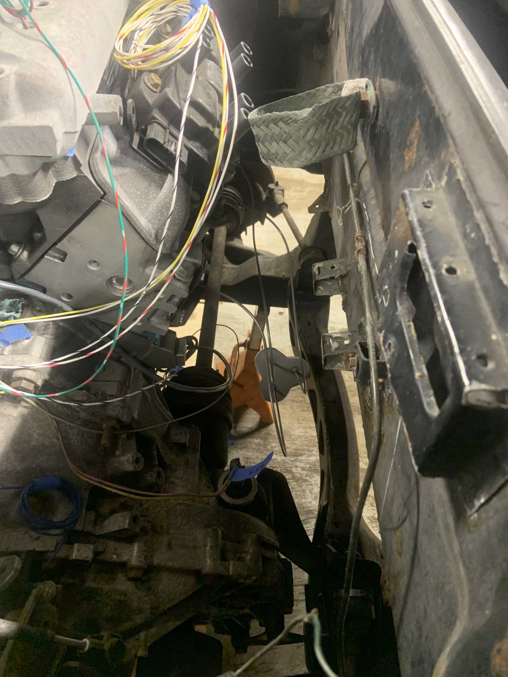
I then started a job I have been dreading, cutting off all the McMaster weld on studs I welded on back in the day, and also cutting off and grinding down the remaining factory brackets. Also going to fix rust in the battery tray, pull the rear crash bar off and paint the inside of the frame rails, fix a couple minor spots of trunk rust, and see if there is any rust to fix behind the wheel liners in the rear. I bought a bunch of paints from Eastwood including some 2K paint to paint the engine bay a nice gloss black, and an interior frame rail paint kit with a whip and 360* spray nozzle to paint the inside of the frame rails thoroughly. Only got a couple pics so far as my phone died on me.
How it was:
Chopped off and ground down, this job sucked and covered my barn in metal dust.
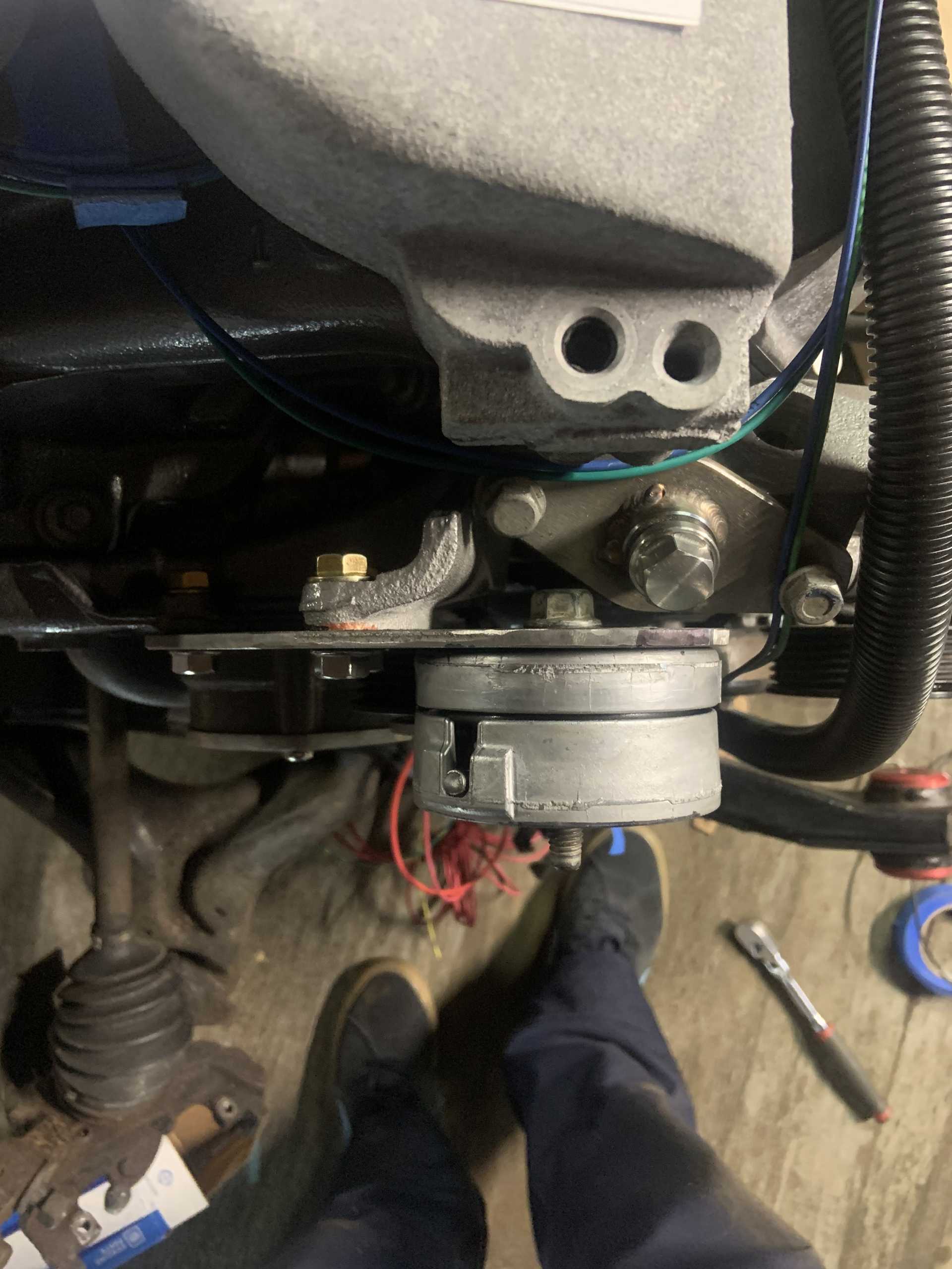
Also removed the torque strut rods, open to advice on which gas shocks to replace their absence with. Might buy a little kiddie pool to make an electrolysis setup to de-rust the crash bars.[This message has been edited by zkhennings (edited 04-19-2023).]
|
|
|
|
82-T/A [At Work]
|
APR 20, 08:33 AM
|
|
| quote | Originally posted by zkhennings:
Been working on the wiring, it has been a lot of research and making diagrams to keep everything straight.
After figuring out what I was doing and making all my diagrams, I paired the harness down to the connectors I need, and trimmed any wires I will be replacing and labelled them to make it easier to see where everything was.
|
|
Sorry, I know this is kind of old, but I was curious what you were going to do with the fusible links. I noticed one of the wires there still has it on there. I can't recall how many wires on the Fiero (either L4 or V6) have it, but I was thinking of replacing all of the fusible links as my daughter works through her car (and later when I redo my V6 Fiero in the winter). I thought it might just be easier to simply buy an aftermarket fuse pod with (however many I need) a specific number of modern fuses... makes it easier to see if I need to trouble-shoot. Just curious what you're going to do with them?
Thanks!
|
|
|
|
zkhennings
|
APR 20, 09:54 AM
|
|
I was either planning to keep them or get new ones to replace them, from my research, fusible links only blow when there is sustained overcurrent, which is probably why they are used for the starter and other things that can pull a massive inrush current. If you sized a fuse to not blow in the same location, it would end up being way too large for the sustained current the fusible link is designed to allow.
It does look like there are specific special fuse boxes that accept a fusible link style fuse, but I will probably just replace the fusible links on an as needed basis with new fusible links. They are cheap, and they are also very unlikely to ever blow unless you have a massive short.
|
|
|
|
82-T/A [At Work]
|
APR 20, 10:57 AM
|
|
| quote | Originally posted by zkhennings:
I was either planning to keep them or get new ones to replace them, from my research, fusible links only blow when there is sustained overcurrent, which is probably why they are used for the starter and other things that can pull a massive inrush current. If you sized a fuse to not blow in the same location, it would end up being way too large for the sustained current the fusible link is designed to allow.
It does look like there are specific special fuse boxes that accept a fusible link style fuse, but I will probably just replace the fusible links on an as needed basis with new fusible links. They are cheap, and they are also very unlikely to ever blow unless you have a massive short. |
|
That's a good point, I suppose it's not something I really need to be concerned with, I've never had one fail... I just like having things like this all in one spot.
EDIT: If like you, I'm going to be going through it anyway... but I'll leave well enough alone and just be sure to identify where specifically they are.
Thanks!!![This message has been edited by 82-T/A [At Work] (edited 04-20-2023).]
|
|
|
|
zkhennings
|
MAY 17, 03:24 PM
|
|
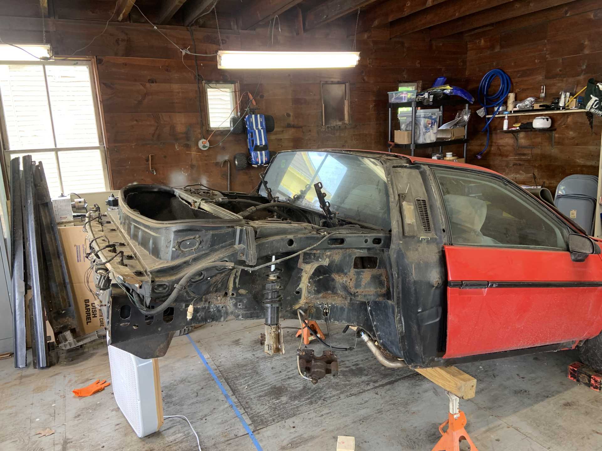
Did the remaining bay shaving.
I bought a box fan and taped an HVAC filter to it, it has been doing a decent job trapping grinding dust and preventing it from landing on everything in my garage.
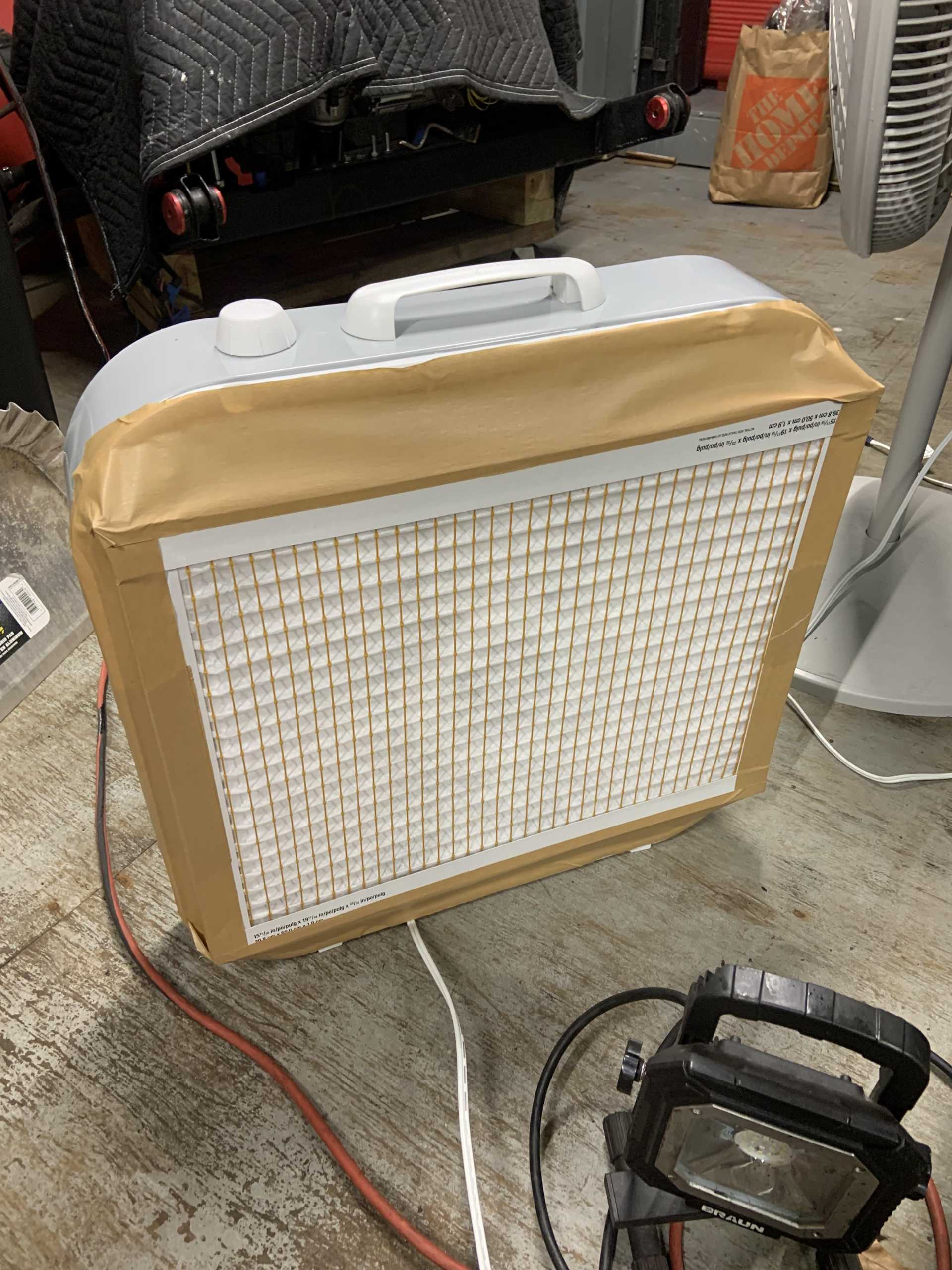
After a few min of grinding...
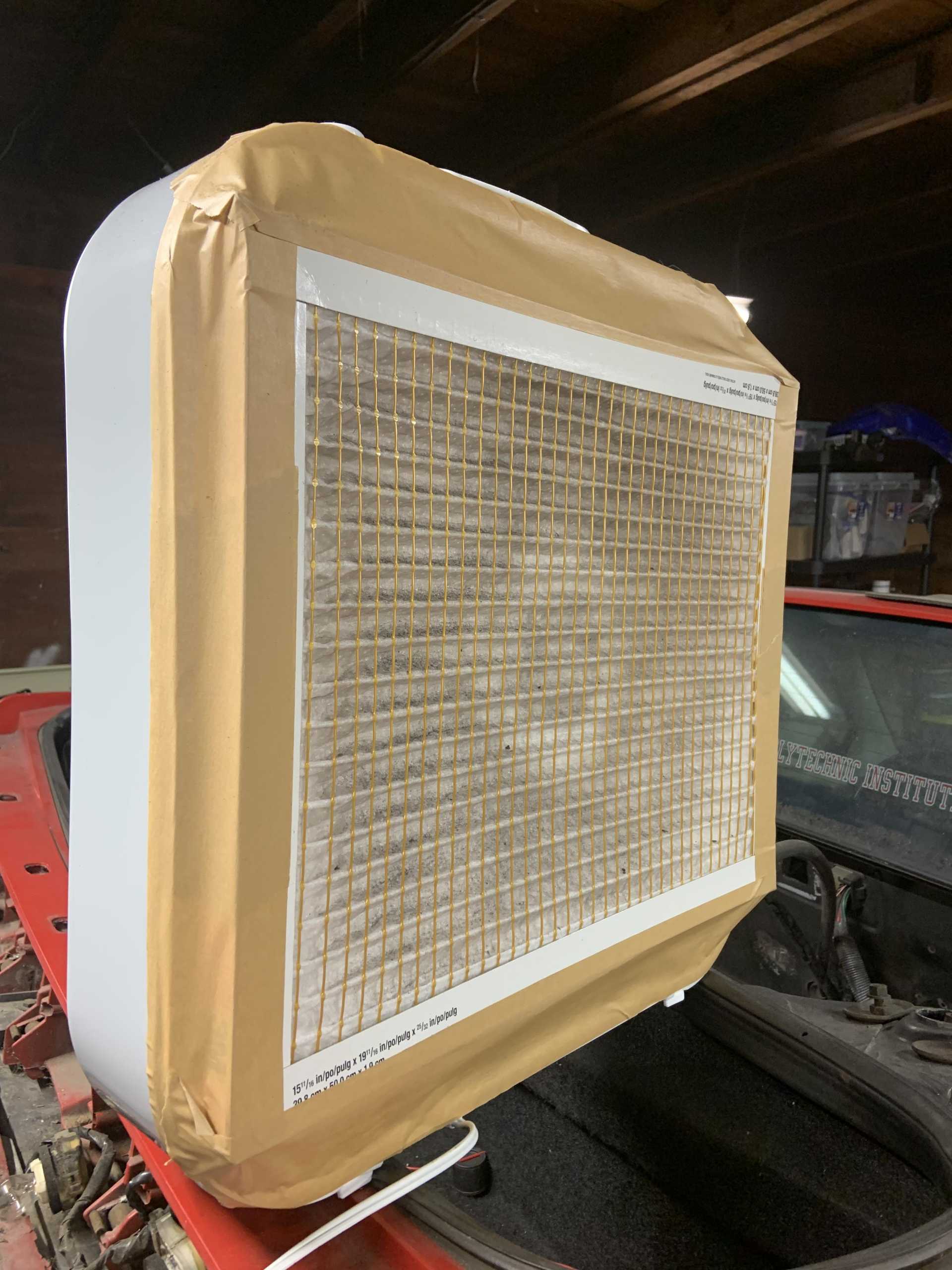
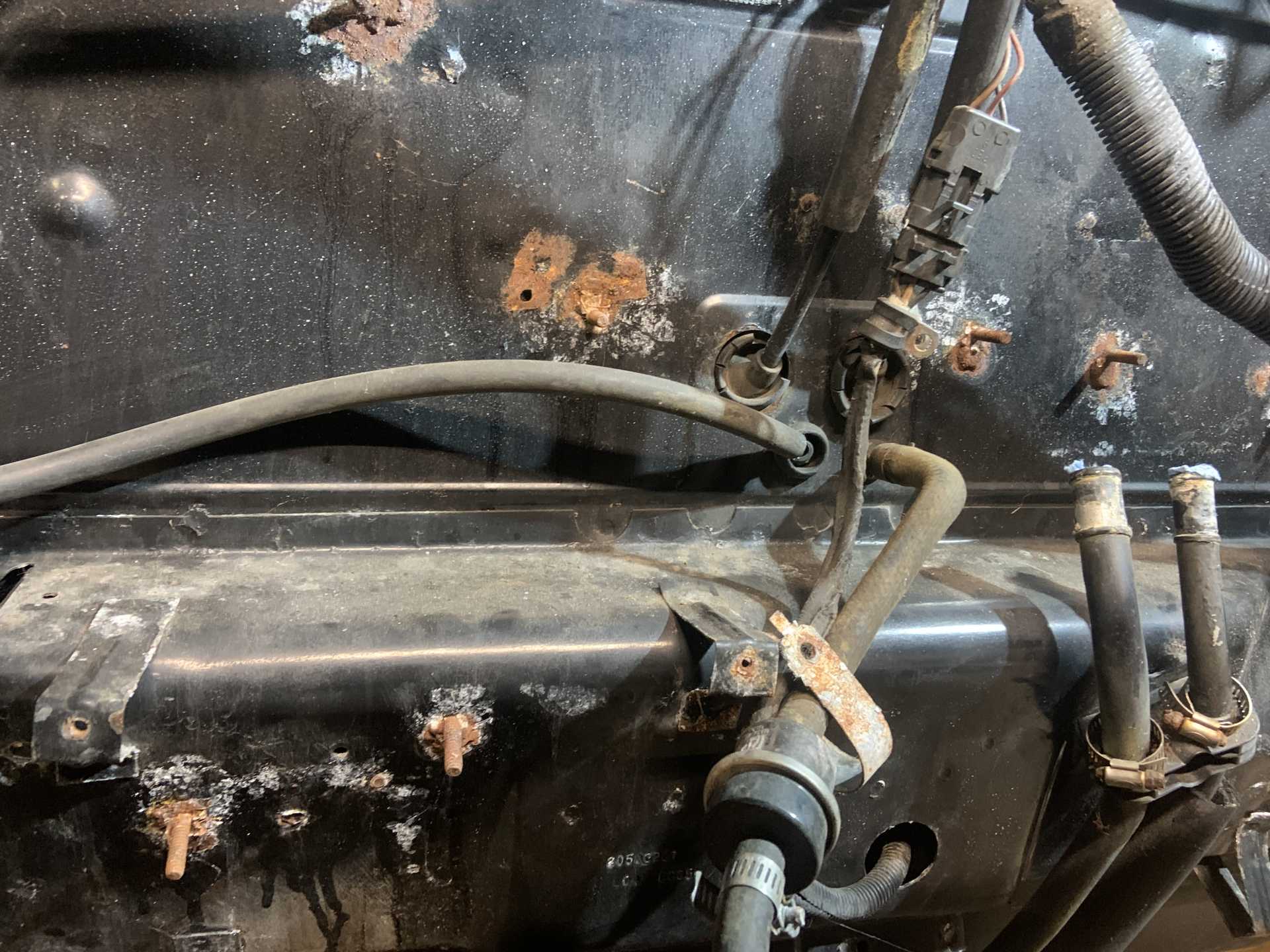
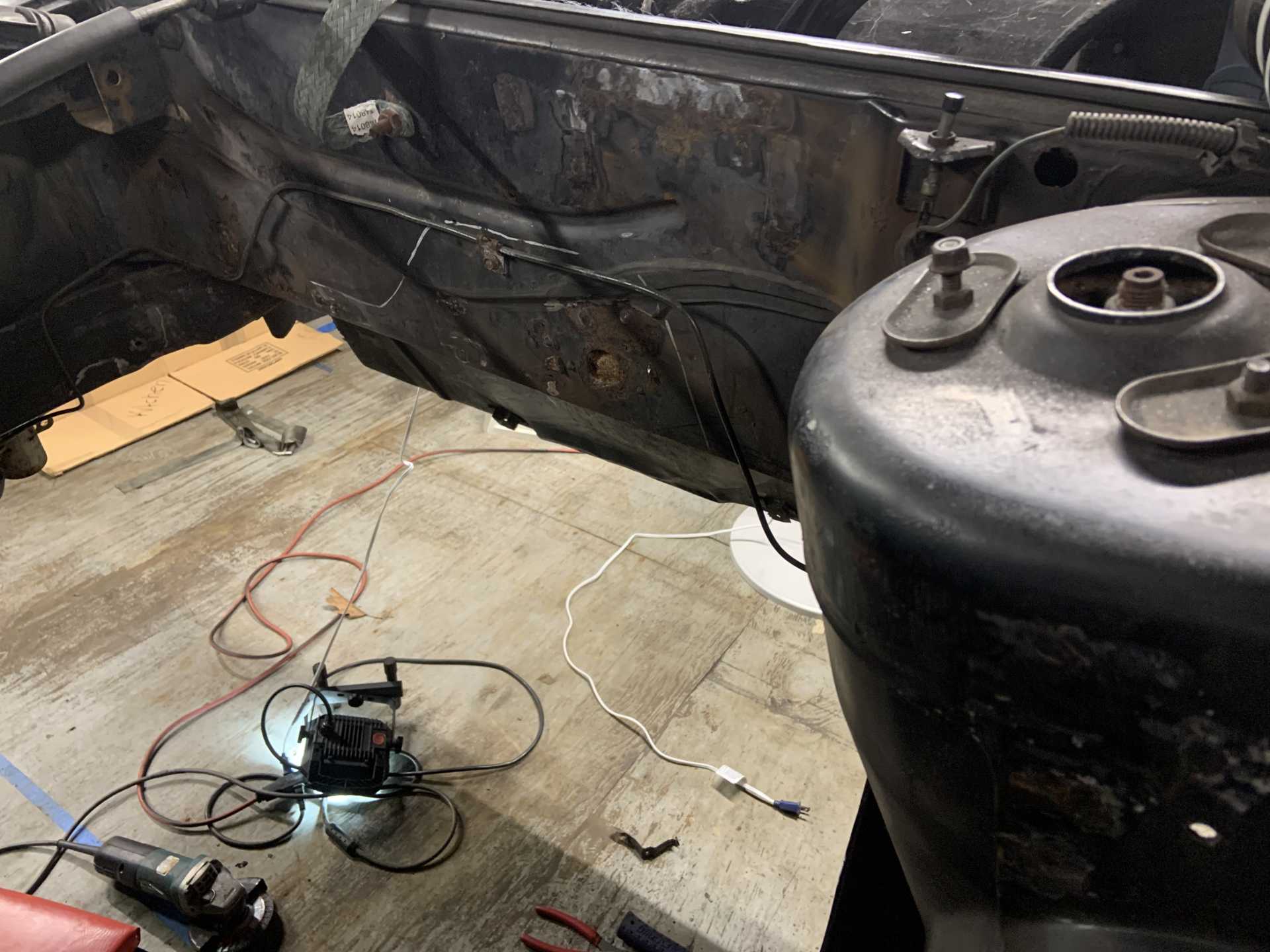
By now it is solid brown. Been exploring for rear end rust to fix, started to take the rear end apart.
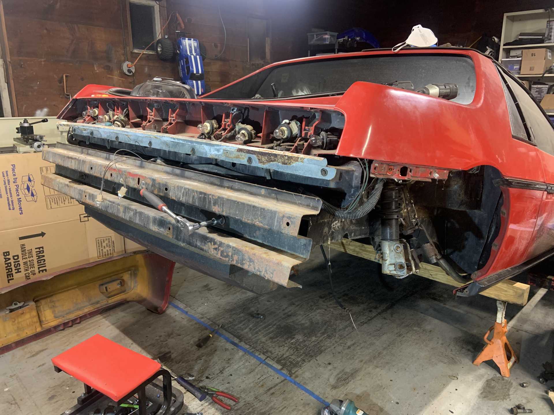
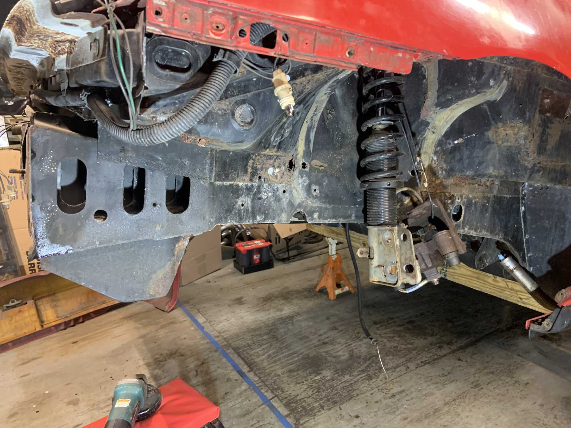
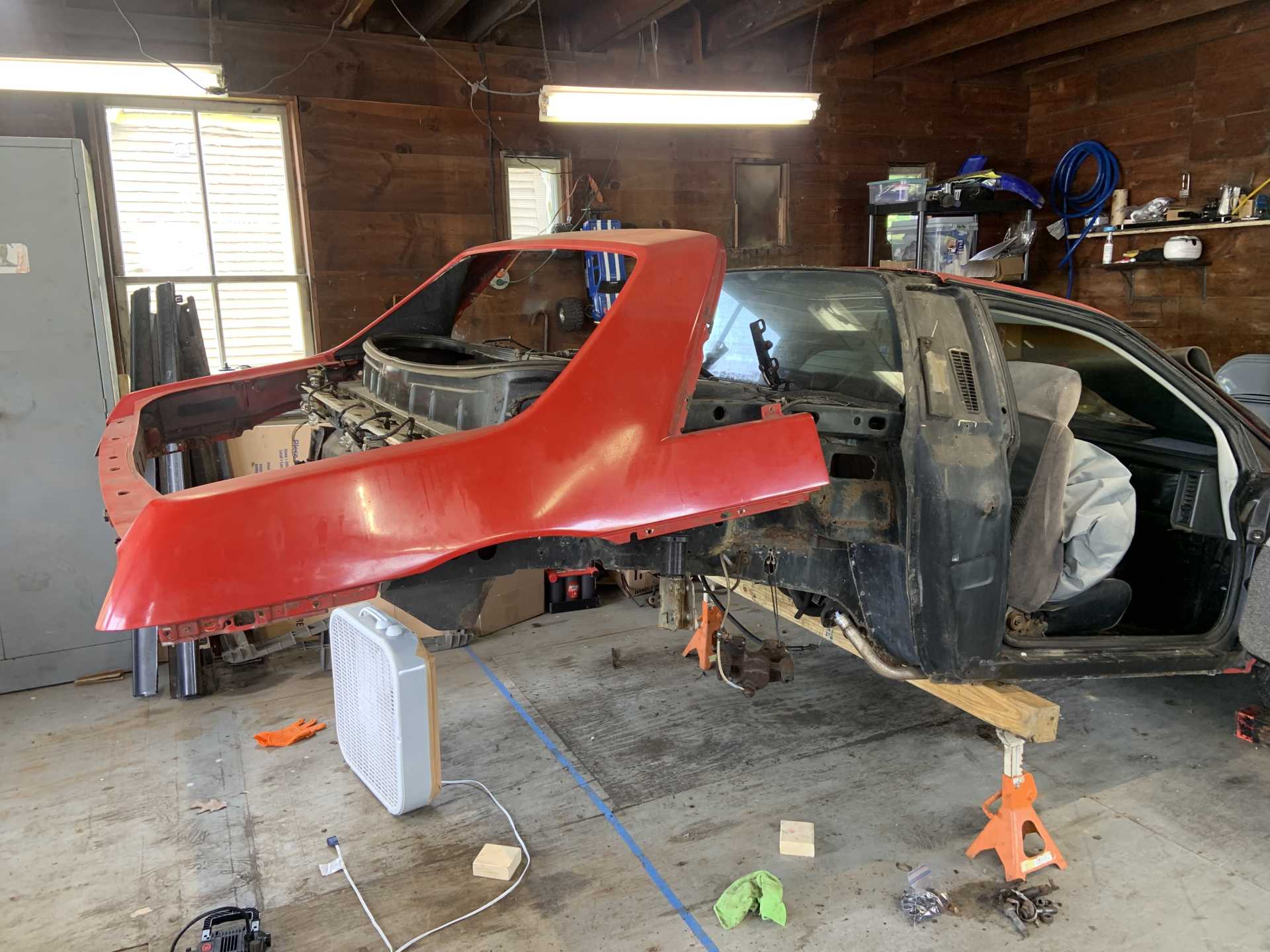
Well there is enough going on and there's no better chance than now to repair all the little spots, so I started taking the rest of the rear end body off. Rockers look great.
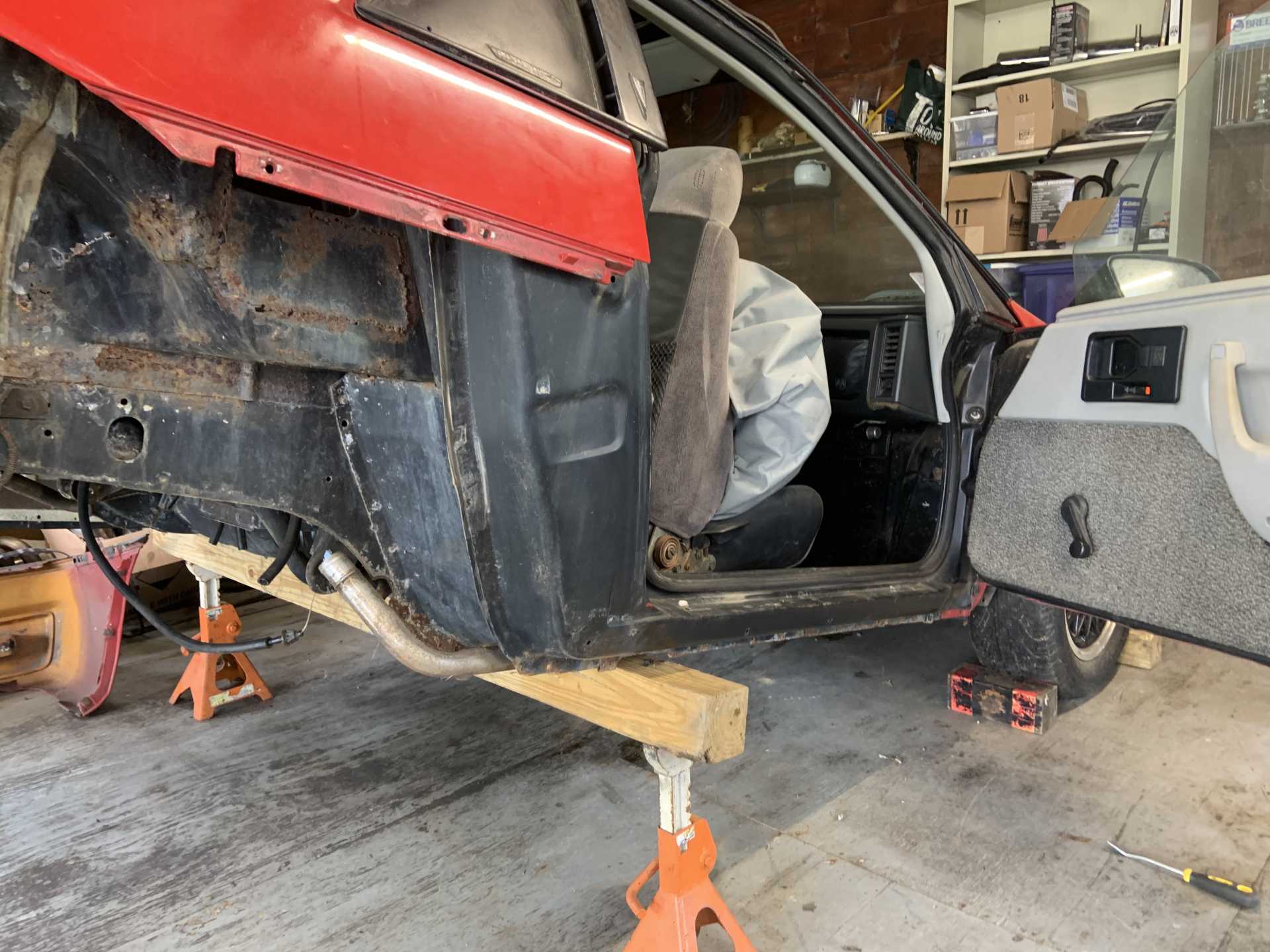
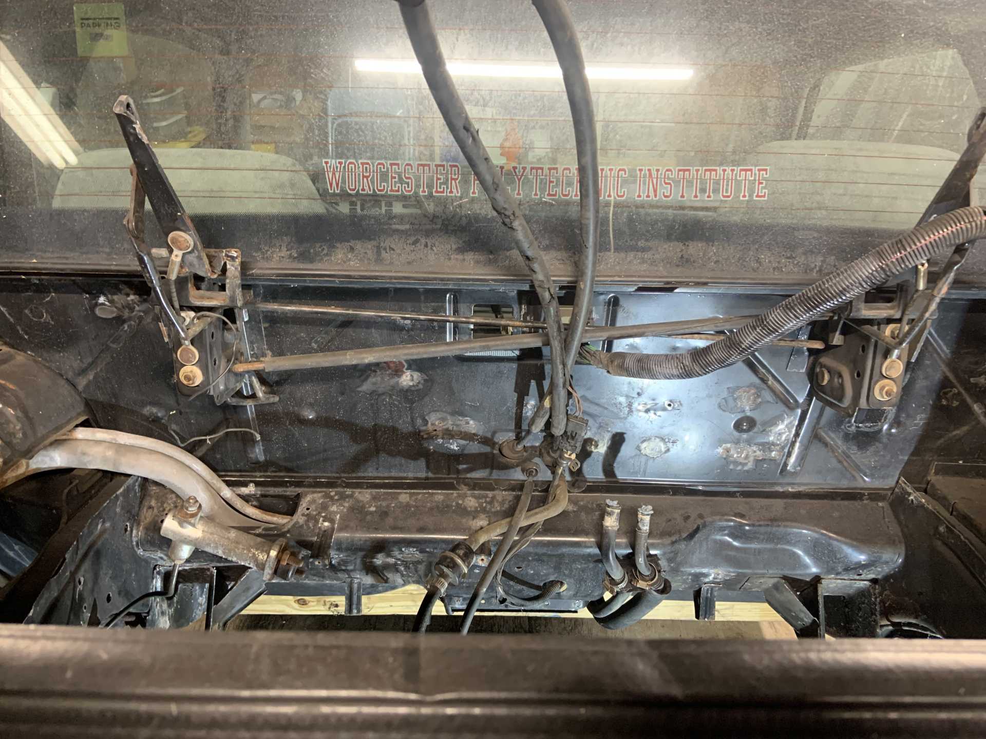
This was a pain to do alone, definitely will need a friend to put it back on.
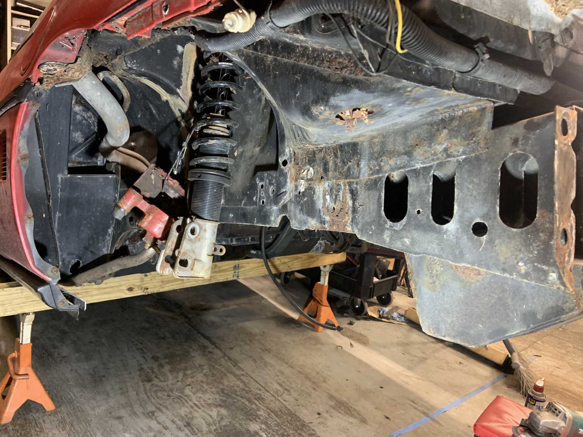
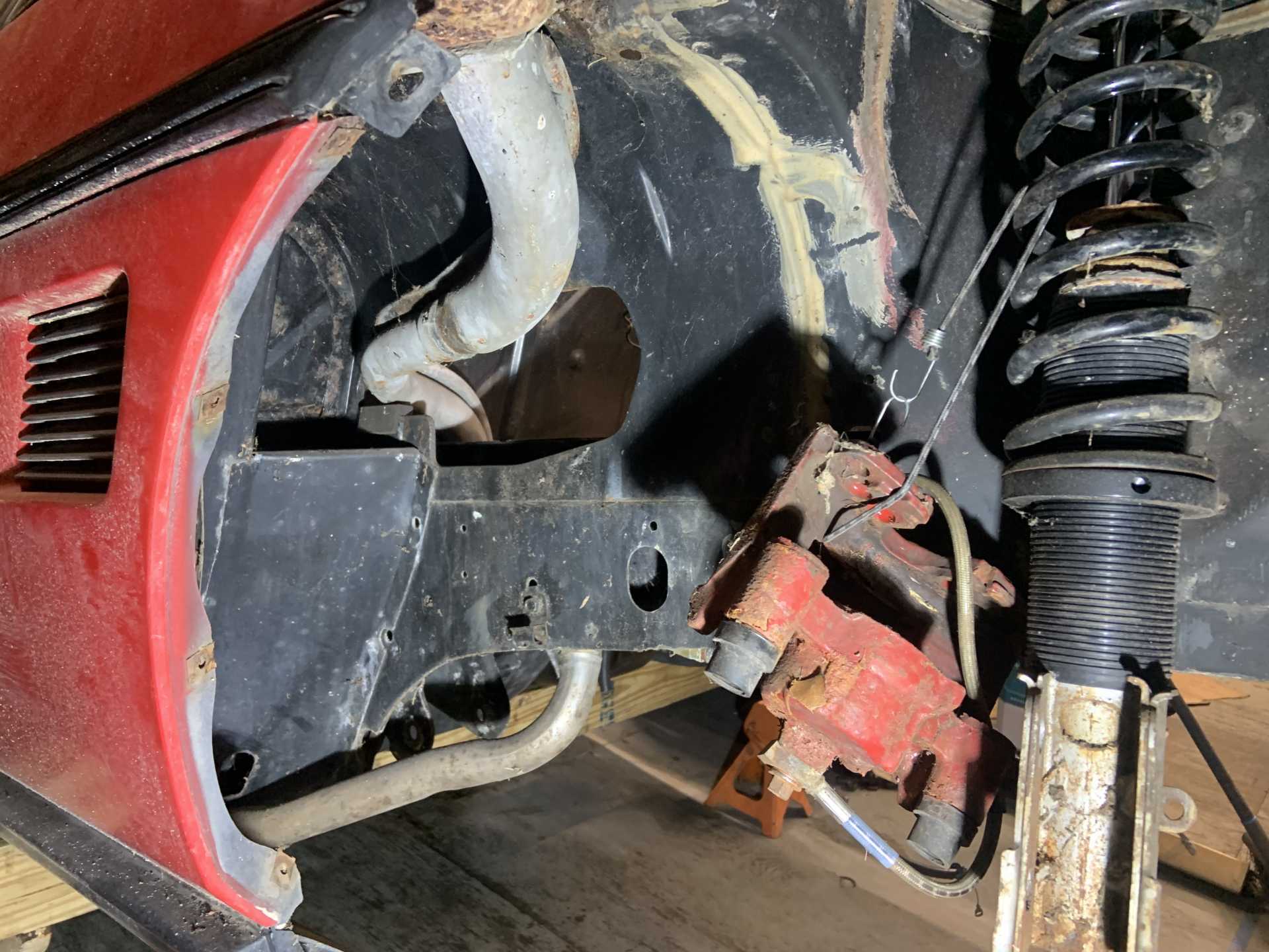
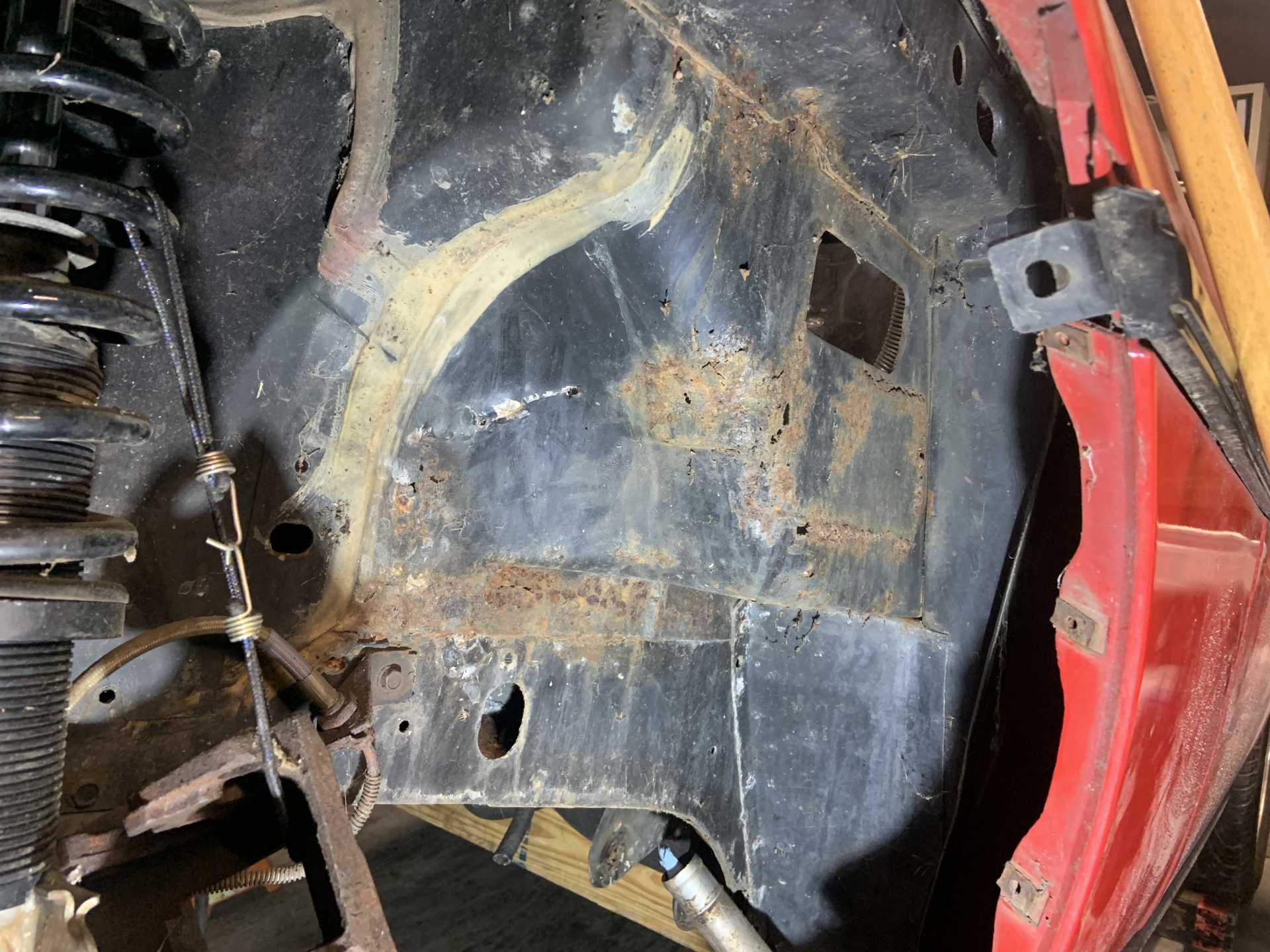
Went ham with the angle grinder with a wire wheel on it to discover all that can be discovered.
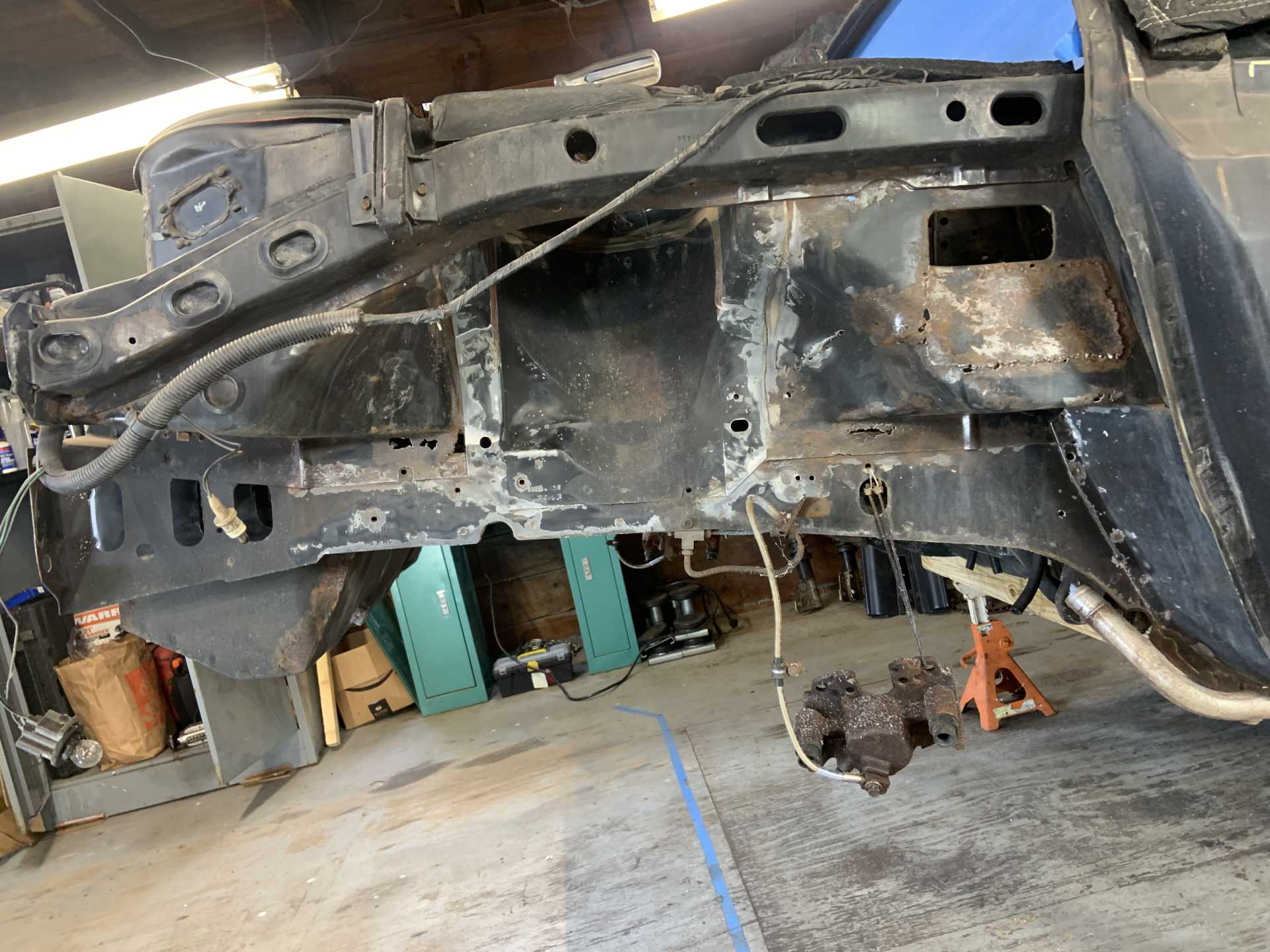
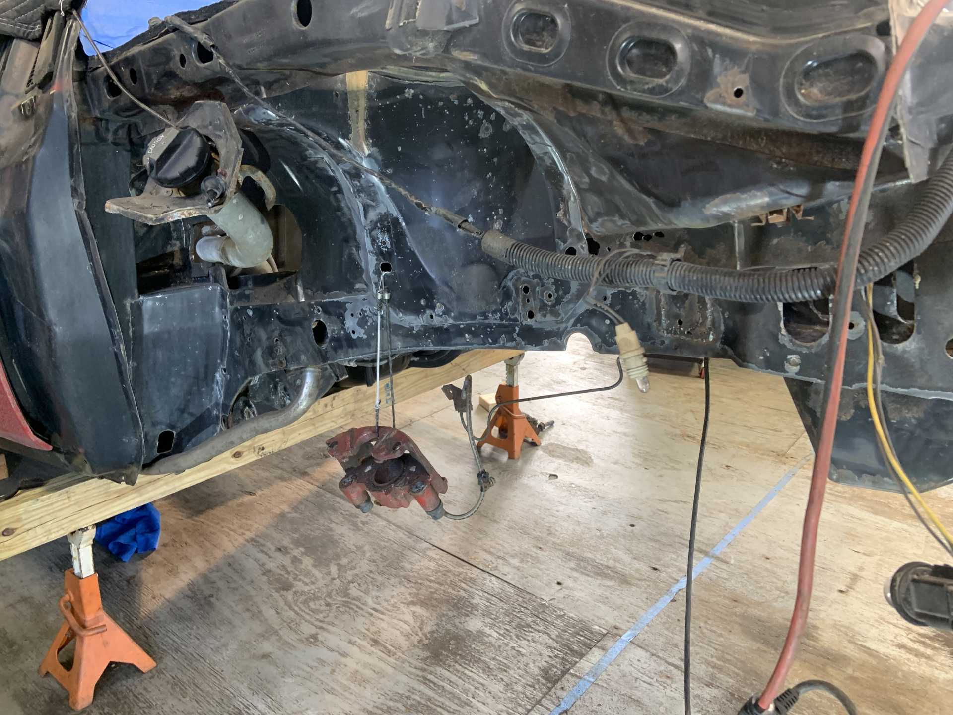
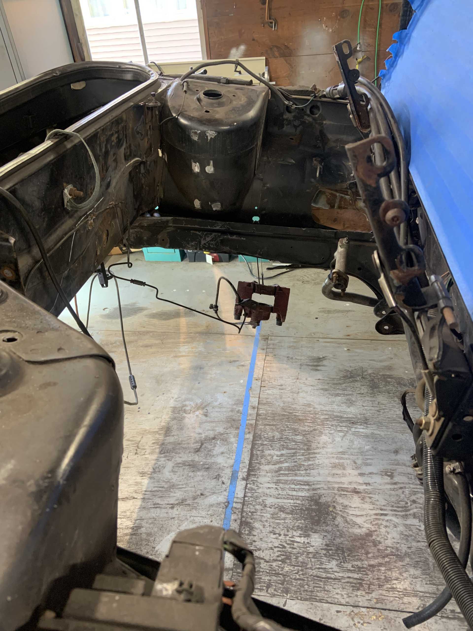
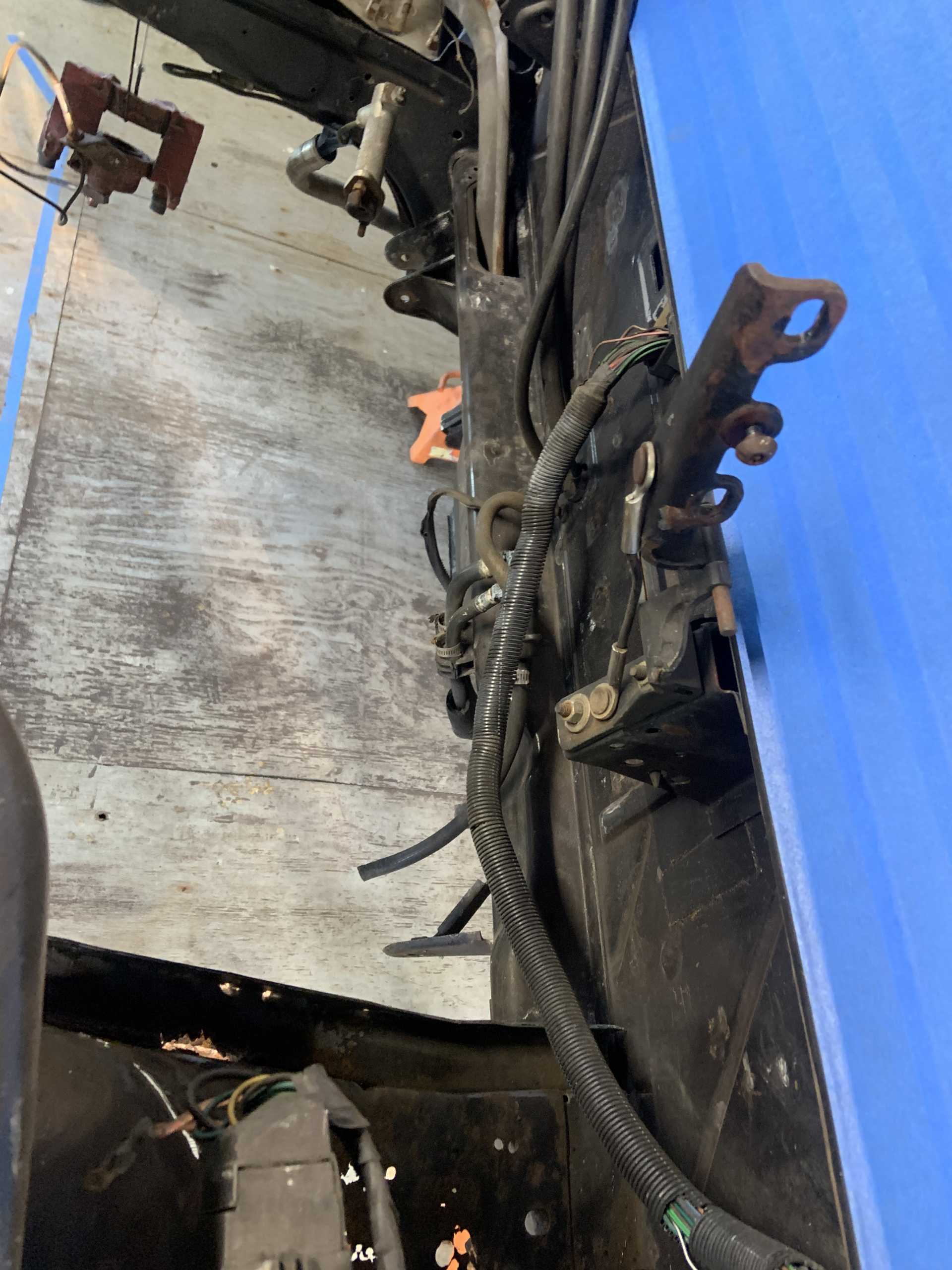
Few spots in the trunk I did not get the chance to get to yet, will need to use the die grinder with a wire wheel to fit in these tighter areas.
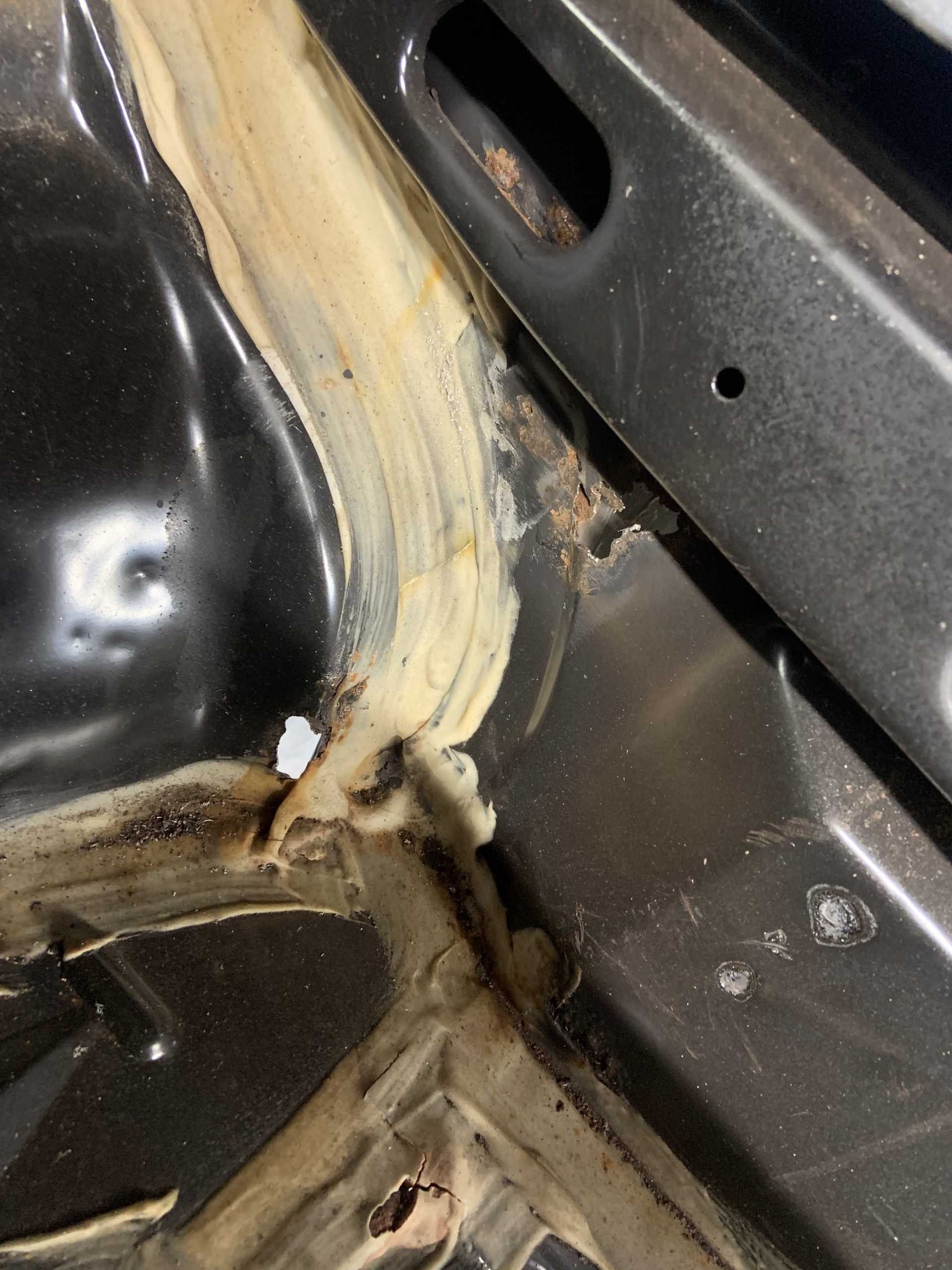
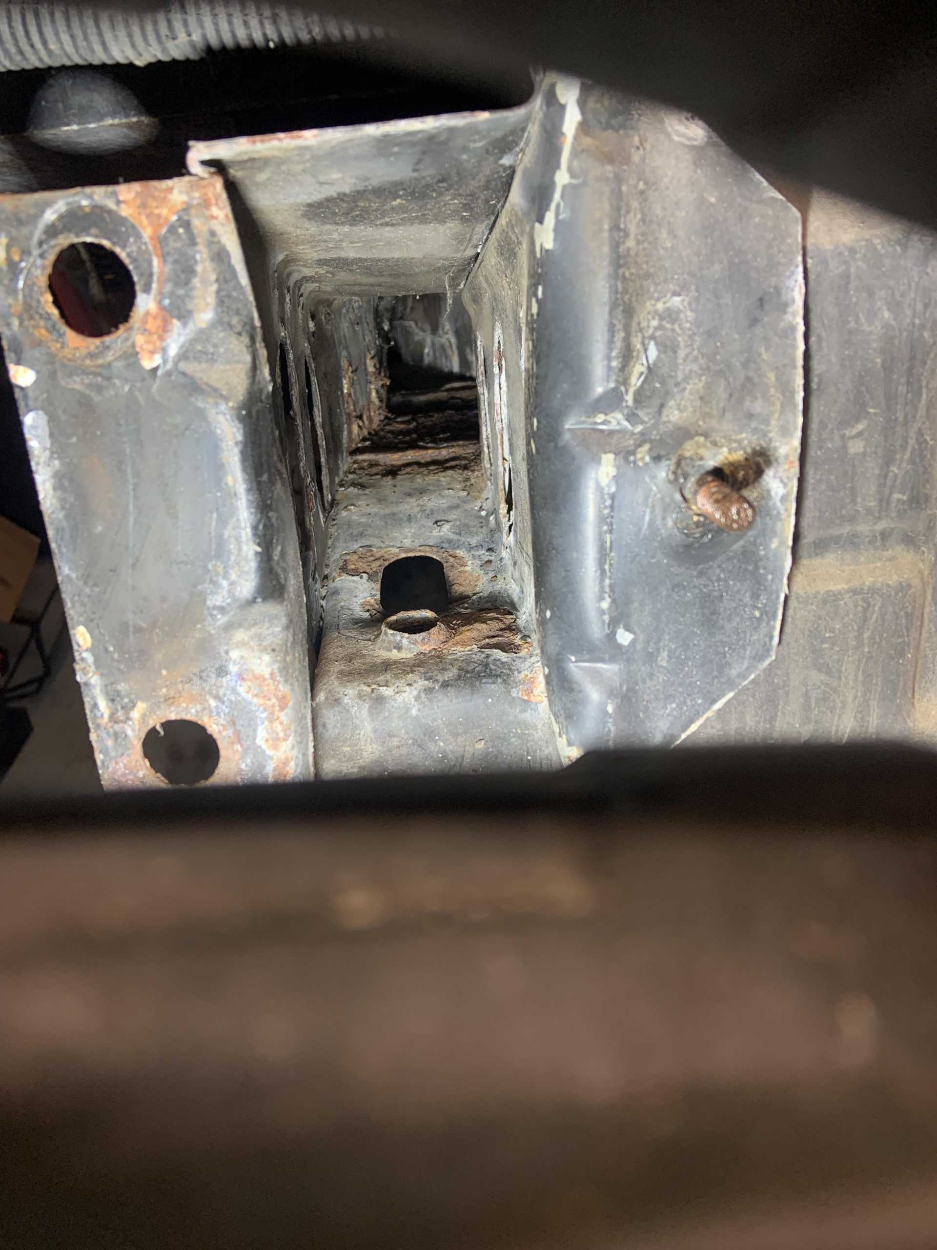
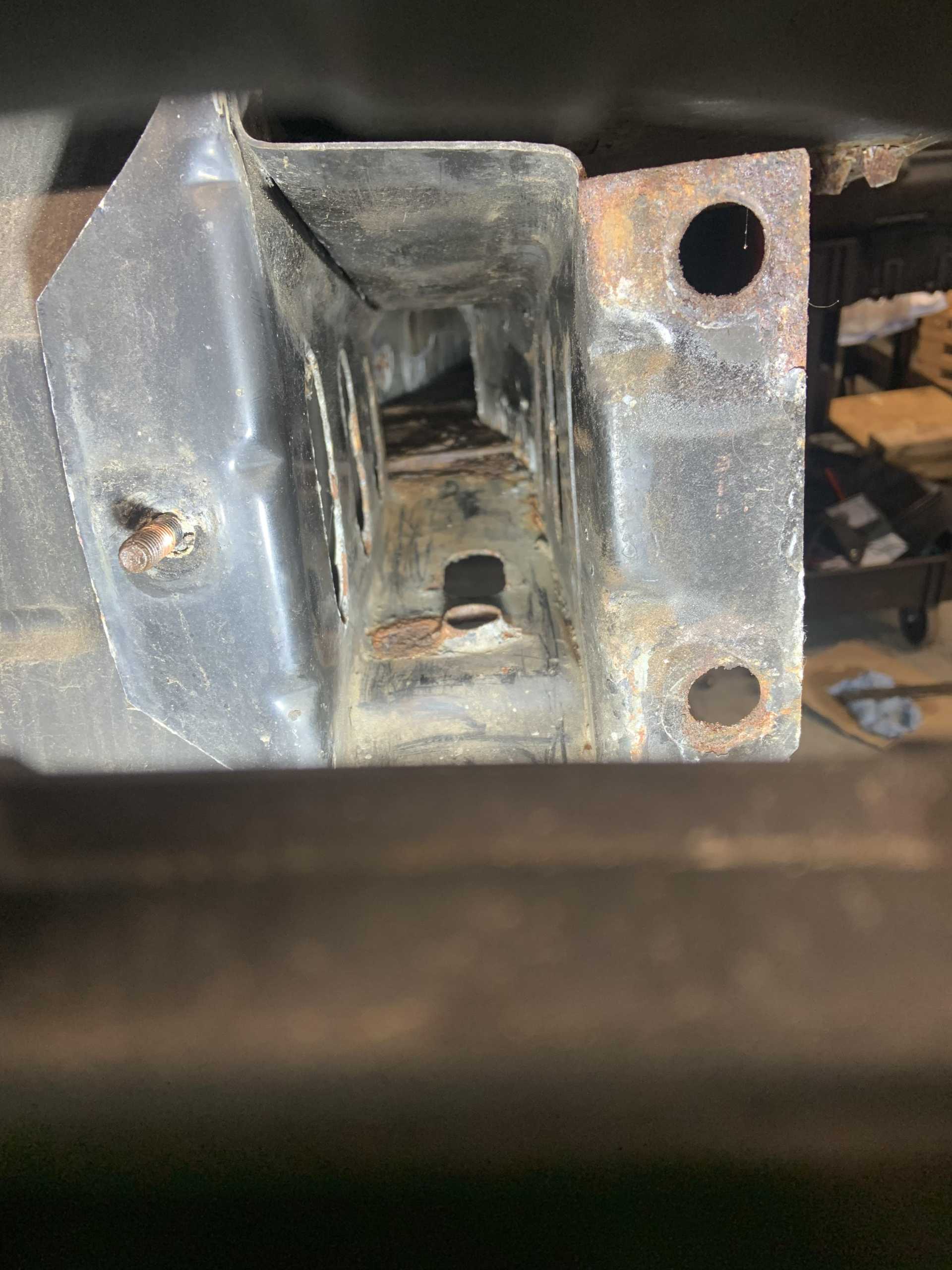
Plan is to start cutting bad sections out and welding in fresh metal, it is not too bad overall. I will paint in the upper and lower frame rails, got a bunch of Eastman products to paint everything with. I do think I am going to chop out the areas where the cradle bushings sit against the underside of the lower frame rails, it is going to be annoying to weld it all upside down so I may chop out the sides of the frame rail in the same area for welding access. Don't really want to, but can't afford weak welds in this area. The whole battery area is getting chopped out, and the rest will just be patches.
|
|
|
|
shemdogg
|
MAY 17, 10:37 PM
|
|
lookin good, doesnt look bad at all. Just a few spots need some love, youll knock that out in no time. Nows the time to make it a fast back  , nice rc truck , nice rc truck
shem
|
|
|
|
zkhennings
|
MAY 18, 01:18 AM
|
|
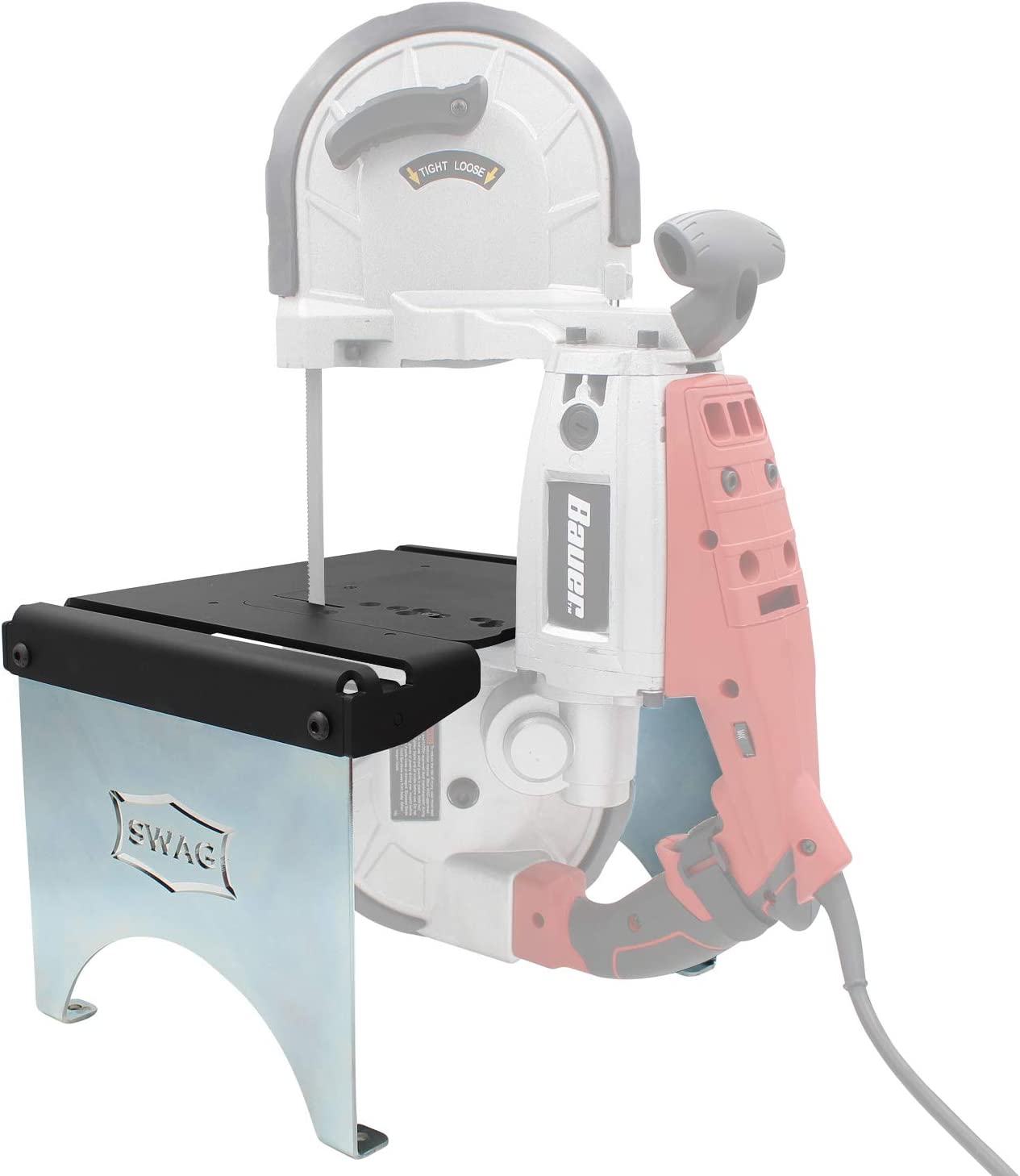
Yea maybe a day or two of cutting grinding and welding. I did order the SWAG table mount kit for my harbor freight handheld bandsaw to turn it into a table mounted one, can't wait to use it and not have to cut all the new bits out with an angle grinder. Check it out. Mounts with just a couple screws if you want to take it off and use it handheld style. Expensive but everyone says it's perfect. They make them for a bunch of different bandsaws.
Funny you bring up the RC car, all my buddies just bought Traxxas cars randomly at the same time this week, I have been getting my brushless Associated MT10 going again as the steering servo was broken and the spur gear was stripped. The one on the wall is a 1/8 scale Associated nitro truck with a 0.5in3 motor which is enormous for an RC, it makes like 3hp. Got a 1/10 scale nitro truck too, swapped in a wicked high power motor back in the day and blew through a diff almost every time I used it. Swapped back to stock motor after I had spent almost $300 on diffs lol. Would wheelie through first, shift into second in the wheelie and wheelie through the whole second gear (only has two gears). Ported the stock motor before swapping it back in and it makes decent power, only baby wheelies though  . Love the nitro but the brushless trucks just break way less because they weigh less, no transmission to mess with, and starting a hot nitro motor everytime you flip it upside down and stall it is a huge pain. The little nitro 2 strokes scream though, I'll get them running again soon if the buddies all stick with RC for more than a week hah. Also have an absolutely stupid little 1/18 scale replica Subaru that I put way too much money into in college, it's like 8" long and does around 80mph, absolutely uncontrollable with the throttle trim all the way up but when I used to rip it around the indoor bball courts in college people couldn't believe how fast it was. . Love the nitro but the brushless trucks just break way less because they weigh less, no transmission to mess with, and starting a hot nitro motor everytime you flip it upside down and stall it is a huge pain. The little nitro 2 strokes scream though, I'll get them running again soon if the buddies all stick with RC for more than a week hah. Also have an absolutely stupid little 1/18 scale replica Subaru that I put way too much money into in college, it's like 8" long and does around 80mph, absolutely uncontrollable with the throttle trim all the way up but when I used to rip it around the indoor bball courts in college people couldn't believe how fast it was.
|
|
|
|