
 
     |
| 85 Speedo, 4000 PPM output possible? (Page 2/3) |

|
Raydar
|
AUG 25, 05:15 PM
|
|
| quote | Originally posted by Spadesluck:
Sidenote, you are correct, www.gmtuners.com seems to be down. |
|
Try again. Working for me, now.
|
|
|
|
pmbrunelle
|
AUG 25, 06:27 PM
|
|
| quote | Originally posted by olejoedad:
Take the signal directly off of the VSS sending unit and build a conversion circuit found on gmtumers.com (Sinister Performance - Tech Section - Wiring Diagrams)
A couple of resistors, a capacitor, a diode and you've got the 4000 ppm squarewave signal you need. |
|
Can you provide a direct link to the article you're talking about?
I found one schematic on this page called "Fiero Speedo Conversion", but it is to convert from a square wave ECM or PCM output to a signal that can be understood by the Fiero speedometer. It is not to convert from a Fiero VSS to square wave.
https://www.gmtuners.com/fiero/fmods.htm
|
|
|
|
pmbrunelle
|
AUG 25, 06:49 PM
|
|
The chip that has 4 wires connected to the gauge is obviously something special to drive the electromagnets in the gauge.
Your best bet is likely to power up the circuit with a VSS connected, spin it in a drill, and probe around with an oscilloscope. If you're lucky, you'll find the 4000 PPM somewhere.
Some key sections:
Is this KiCad? Thank you for adding to the forum with the schematic, even if it is imperfect.
********************************************************************************
If you can't find the 4000 PPM signal anywhere, for information, the 2000 PPM signal has a 50% duty cycle, so it has 4000 evenly spaced edges per mile. So you could generate a pulse for each edge (rising AND falling) and have 4000 PPM.[This message has been edited by pmbrunelle (edited 08-25-2025).]
|
|
|
|
TGYK256
|
AUG 25, 07:11 PM
|
|
| quote | Originally posted by pmbrunelle:
The chip that has 4 wires connected to the gauge is obviously something special to drive the electromagnets in the gauge.
Your best bet is likely to power up the circuit with a VSS connected, spin it in a drill, and probe around with an oscilloscope. If you're lucky, you'll find the 4000 PPM somewhere.
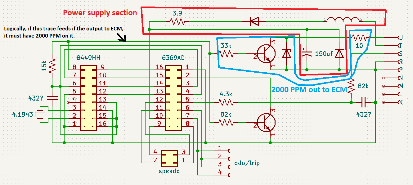
For information, this is the power supply section:
The resistor and zener diode form a shunt voltage regulator. The 150 uF capacitor forms a local power supply at the gauge. The non-zener diodes protect the gauge from damage in case the battery is connected with a reverse polarity.
Is this KiCad? Thank you for adding to the forum with the schematic, even if it is imperfect.
********************************************************************************
If you can't find the 4000 PPM signal anywhere, for information, the 2000 PPM signal has a 50% duty cycle, so it has 4000 evenly spaced edges per mile. So you could generate a pulse for each edge (rising AND falling) and have 4000 PPM.
|
|
I suspect that it's some sort of 3-coil/2-meter air core meter driver, and find it odd that there is so many parallel connections to the next chip over. It leads me to suspect that it is using some early adoption of SPI, but the tech era leads me to think that the other chip is too small to be an MCU.. But I am unsure. I do know for sure that the non-driver IC doesn't have a connection to the voltage rail feeding the meter driver for VCC, which implies a regulated supply in one of the parallel connections or a completely passive component.
Unfortunately I have reached a fairly similar conclusion in that I will need to probe around to find a signal. I'll have to go pull my oscilloscope out of storage and figure a way to drive the VSS input as I don't have a spare VSS to test with, and don't want to risk losing my gear to the bowels of my transmission. I might have to resort to testing in-vehicle with it up on jackstands.
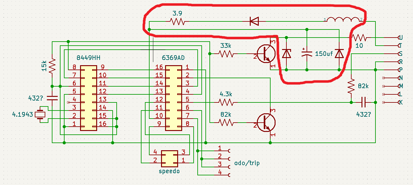
I had identified (and poorly laid out) the input power supply section while looking over the layout, improperly identifying the lower right diode as not being a zener. I suspect that the inductor is for noise reduction and the resistor for overall current limiting. I do use KiCad, as it's free and runs well enough for my needs of circuit documentation; Good eye!
If I do end up going the route of an edge-detection-driven signal generator, I haven't been able to find out for sure if the GM digital cruise module (Marked "V8") expects a square or sine wave. I suspect square, as I've seen mention of the 4k signal being generated by the ECM in newer vehicles, and need to be conditioned into a sine to work the speedometer in the Fiero.
|
|
|
|
pmbrunelle
|
AUG 25, 07:52 PM
|
|
| quote | Originally posted by TGYK256:
If I do end up going the route of an edge-detection-driven signal generator, I haven't been able to find out for sure if the GM digital cruise module (Marked "V8") expects a square or sine wave. I suspect square, as I've seen mention of the 4k signal being generated by the ECM in newer vehicles, and need to be conditioned into a sine to work the speedometer in the Fiero. |
|
The Fiero was in the beginnings of fuel injection at GM, so it doesn't do some things the standard GM way.
In the Fiero, the VSS goes to the speedo board, which squares up the sine wave and sends it to the ECM.
In the more "standard GM" way, the VSS goes to the ECM, which squares it up, and then it provides an output to the instrument cluster.
The above circuit is a differentiator. I don't know if Sinister Performance himself developed this. No credit is given to any other author, so it must be him!
It generates voltage spikes on each square wave edge. The output is quite far away from being a sine wave, but the Fiero community has found that this circuit works to convert a square wave output into something (not sine) that can be correctly interpreted by the Fiero speedometer.
|
|
|
|
olejoedad
|
AUG 25, 09:39 PM
|
|
My bad!
I was thinking backwards - we use that circuit to take the digital output from the 'normal' GM PCM's
and make it something the Fiero speedo can live with.
Apologies!  
I have edited my initial posting.[This message has been edited by olejoedad (edited 08-25-2025).]
|
|
|
|
TGYK256
|
AUG 27, 07:00 AM
|
|
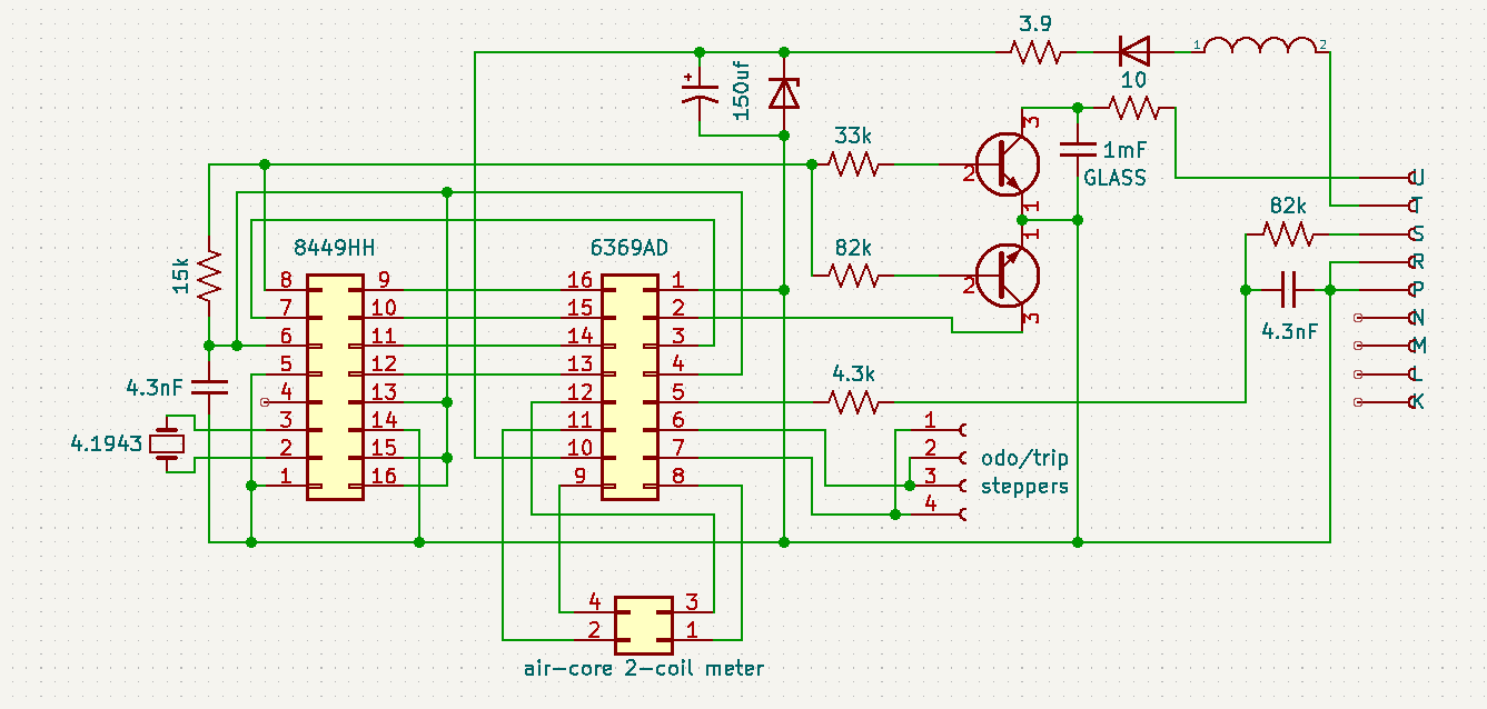
I heard back from Oliver over email (ty Spadesluck) and he did confirm to me that he believes there isn't a buffered 4000 ppm signal on these older boards, and that it seems the signal division is done internal to the first IC. Short of probing around on the board in-vehicle with the back end up in the air, I don't really have the means to confirm or deny this for certain. (I don't have spare vss or function generator) That being said, I did update the schematic and attempted to clean it up for anyone who might need it in the future.
As far as my need for a viable signal goes, I have been looking into options for variable-frequency frequency-doubling circuits.. And short of some specialized low-freq PLL stuff, I think this might best be handled via a microcontroller calculating pulsewidth and triggering on each edge of the 2k ppm signal. Unfortunately that solution will take some time to get into a functional state, but I have started on a design to be plugged into C246 where the old cruise module connected originally. If any EE-inclined members want to look it over and give some tips, I would greatly appreciate it; My electrical skill is more about diag/repair, much less about electrical circuit design.
Regardless, thank you to everyone who has reached out or replied here! Really awesome to see our niche group being so friendly and helpful.
|
|
|
|
pmbrunelle
|
AUG 27, 08:43 AM
|
|
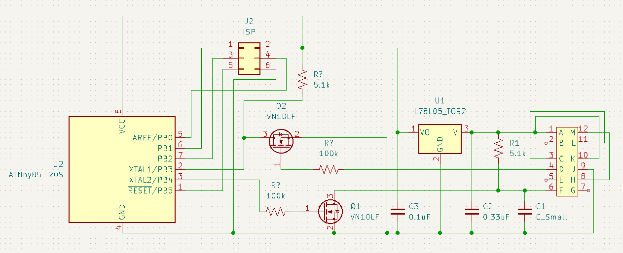
Next time, before submitting a schematic for review, please assign reference designators to all components. When many compoments are labelled with question marks, that makes it hard to talk about a specific part.
A hypothesis and logical consequence:
If the 86+ speedo board works mainly at 5V, and the signal to the cruise module is just passed over a simple wire (no voltage level modification), then this implies that the cruise module works with a 5V square wave input.
If the inputs/outputs operate at 5V, then you could eliminate Q1, Q2 (and their associated 100kΩ / 5.1kΩ resistors), and the design considerations that they imply.
For the input, I think a 10kΩ resistor between the 2000 PPM signal and microcontroller pin would suffice. This would limit current into the protection diodes of the input pin, if that were to happen.
For the output, I think a 100Ω resistor (for some small short-circuit protection) between the microcontroller and C1 would suffice. What is the value of C1? Undecided? Perhaps 10 nF would not slow down the signal too much?
A diode in series with the 12V power input would protect the circuit against a reverse-polarity battery connection. This is standard practice in automotive.
You have output capacitor C3 at the regulator output, but it is also customary to decouple the power supply locally right at the microcontroller. Some capacitance installed as directly as possible between the VCC and GND pins of the microcontroller pins would be preferred. The datasheet of the microcontroller likely gives a suggested configuration of decoupling capacitance.
When the programmer is not connected to the ISP connector, the nRESET pin is left floating in the air. Stray voltage could cause the pin to go high or low, possibly randomly resetting the microcontroller. This pin should probably be tied to VCC through a resistor, but again, check the datasheet of the microcontroller for the suggested reset circuit configuration.
|
|
|
|
TGYK256
|
AUG 27, 09:24 AM
|
|
| quote | Originally posted by pmbrunelle:
Next time, before submitting a schematic for review, please assign reference designators to all components. When many compoments are labelled with question marks, that makes it hard to talk about a specific part.
A hypothesis and logical consequence:
If the 86+ speedo board works mainly at 5V, and the signal to the cruise module is just passed over a simple wire (no voltage level modification), then this implies that the cruise module works with a 5V square wave input.
If the inputs/outputs operate at 5V, then you could eliminate Q1, Q2 (and their associated 100kΩ / 5.1kΩ resistors), and the design considerations that they imply.
For the input, I think a 10kΩ resistor between the 2000 PPM signal and microcontroller pin would suffice. This would limit current into the protection diodes of the input pin, if that were to happen.
For the output, I think a 100Ω resistor (for some small short-circuit protection) between the microcontroller and C1 would suffice. What is the value of C1? Undecided? Perhaps 10 nF would not slow down the signal too much?
A diode in series with the 12V power input would protect the circuit against a reverse-polarity battery connection. This is standard practice in automotive.
You have output capacitor C3 at the regulator output, but it is also customary to decouple the power supply locally right at the microcontroller. Some capacitance installed as directly as possible between the VCC and GND pins of the microcontroller pins would be preferred. The datasheet of the microcontroller likely gives a suggested configuration of decoupling capacitance.
When the programmer is not connected to the ISP connector, the nRESET pin is left floating in the air. Stray voltage could cause the pin to go high or low, possibly randomly resetting the microcontroller. This pin should probably be tied to VCC through a resistor, but again, check the datasheet of the microcontroller for the suggested reset circuit configuration. |
|
Thank you for the reply! I do apologize about the unlabeled components- I caught it just after I hit the post button.. As for the FET-switched signals for level shifting, according to the I/O schematic for the 1226864/1226156, the VSS input to the ECM from the speedo is pulled to 12v by a 5.1k resistor inside the ECM, and the speedo board triggers to ground through a transistor for signal formation. Along those lines, I am assuming a 0-12v square-wave.
I hadn't considered reverse voltage protection, but you are absolutely right in that it should be a standard consideration. As for the 5v supply, I was unable to find mention of it in the ATTiny datasheet with a quick ctrl+f search, and I have yet to do any PCB layout, but I am figuring that the regulator and output filter cap may be close enough onboard to prevent any issues. I had also considered using a resistor/zener dropper for a crude 5v supply, but figured that would be less stable than a linear regulator, require even more filtering, be less energy efficient, and likely end up costing more than the regulator + caps.
I will definitely use a pullup for the reset pin, as well as a current-limiting resistor for the signal output; Both things I had overlooked as well. The value of C1 hadn't been determined yet, but I figured I will likely want something there for switching noise reduction. The operating frequency range of the 4k ppm signal will be around 20-90 Hz, corresponding with a 20-80 mph range, and I hadn't been sure how that corresponds to capacitance value for filtering. Hoping I don't need to use an RC LPF to prevent harmonics.
|
|
|
|
TGYK256
|
AUG 27, 11:22 AM
|
|
Updated mcu doubler schematic for consideration:
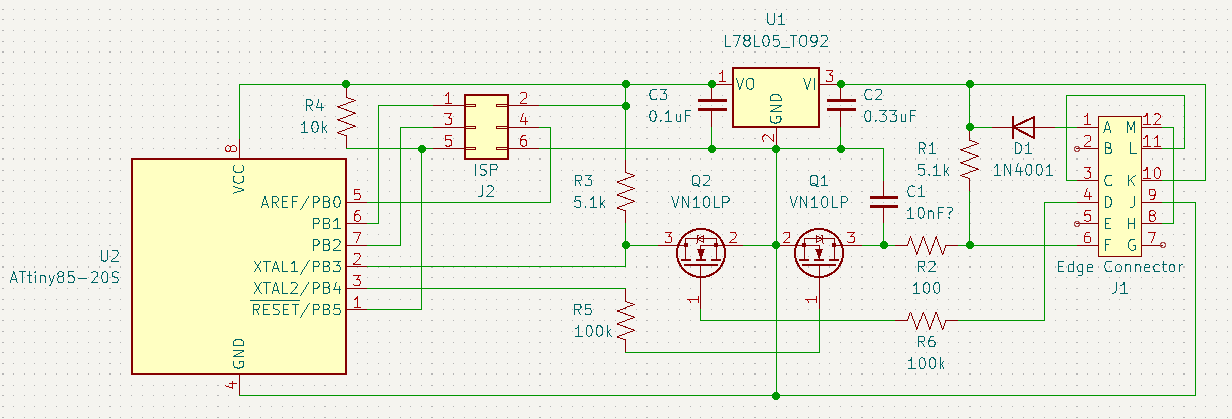
I kinda really like the no-splice/no-cut mod idea, so I will probably be moving forward with designing and ordering some pcbs and such once I am confident in the schematic. If I get it to work, I'll release the code for the MCU, as well as the full KiCad project open-source on GitHub.
|
|
|
|