|
| Code 13 - 87 SE (Page 2/2) |

|
MERATIME
|
APR 14, 11:23 AM
|
|
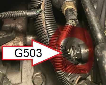
Just to reconfirm, is this the G503 connection on the image below? I have found information about the G503 for the 2.8. But I can’t find it for the Iron Duke which mine is equipped with.
Thanks.
|
|
|
|
Vintage-Nut
|
APR 14, 12:52 PM
|
|
No
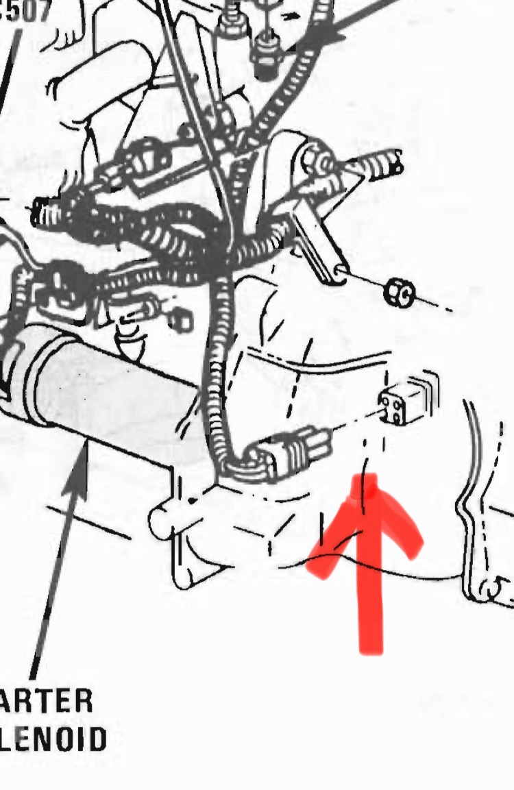
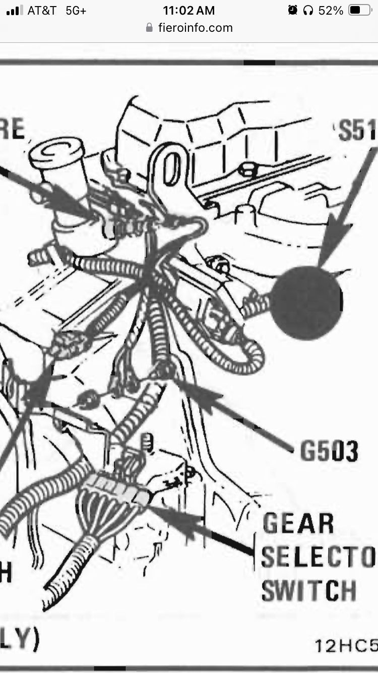
I posted the location of G503 on a 2.5L in the service manual
It is on page 8A - 201 - 2 / Figure B
If you don't have a printed manual; on *This* digital 1987 Pontiac Fiero Service Manual is on page 1035
https://fieroinfo.com/manua...M_Service_Manual.pdf[This message has been edited by Vintage-Nut (edited 04-14-2025).]
|
|
|
|
olejoedad
|
APR 14, 12:58 PM
|
|
No, that is not the G503.
In electrical nomenclature.....
G is a ground
S is a splice
C is a connector
100 is front compartment.
200 is interior
300 is typically engine compartment
400 is typically rear lights
500 would also be back there somewhere.
If I had access to my FSM' I could give you exact locations for each, but they are at home, and I am not![This message has been edited by olejoedad (edited 04-14-2025).]
|
|
|
|
MERATIME
|
APR 14, 02:10 PM
|
|
Ahh… Now I see.Thank you both.
|
|
|
|
MERATIME
|
APR 15, 12:00 AM
|
|
Hello all !
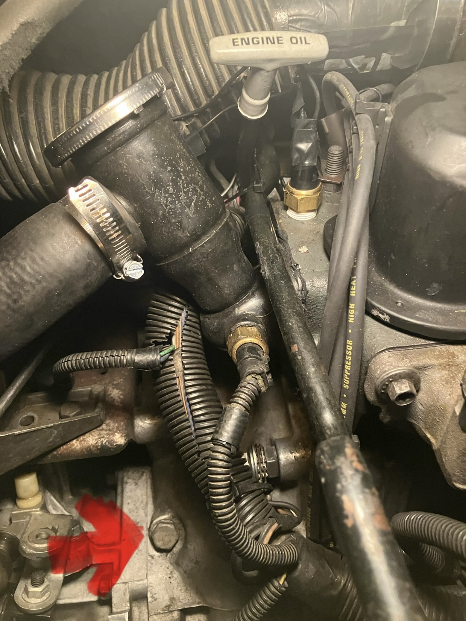
I am now looking in the engine area of this Fiero SE. I was trying to double check the locations of those negative looped wires mentionedand this is where I found them in this first image below:
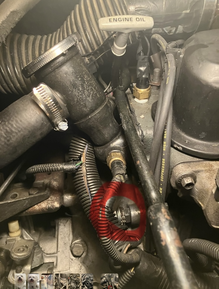
My question is if these negative wires in the right location or should they be attached to the bolt below showing in the second image?
Please let me know if what you see on the first image is the correct connection for G503. I couldn’t tell in the service manual on page 8A – 201–2 specifically which exact connecting the negative wires attached to for the location of G503.
Thank you for your input.
|
|
|
|
MERATIME
|
APR 15, 12:01 AM
|
|
Hello all !
I am now looking in the engine area of this Fiero SE. I was trying to double check the locations of those negative looped wires mentionedand.
This is where I found them in this first image below:
Note: It seems that these wires were connected to a bolt that attaches the transmission to the engine block. I did not do this. This was how the vehicle was when I got it back after the engine rebuild.
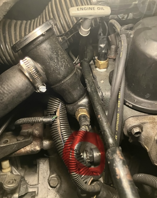
My question is if these negative wires are mounted in the right location or should they be attached to the bolt below showing in the second image?
Please let me know if what you see on the first image is the correct connection for G503. I couldn’t tell in the service manual on page 8A – 201–2 specifically which exact connecting spot the negative wires attached to for the location of G503.
Thank you for your input.[This message has been edited by MERATIME (edited 04-16-2025).]
|
|
|
|
Vintage-Nut
|
APR 15, 08:11 AM
|
|
|
|
|
MERATIME
|
APR 15, 10:44 AM
|
|
|
Thank you Vintage-Nut ! I will now remove those wires, clean the wires loops & stud , then reconnect. Hopefully that will take care of the Code 13.
|
|

|
Vintage-Nut
|
APR 15, 10:51 AM
|
|
As I mentioned, Consider the Engine-to-Chassis Ground Strap Connection in the Path
Measure the Resistance from G503 to three points:
*To the Battery
*To the Chassis End of the Ground Strap
*To the Engine End of the Ground Strap
You want a very low resistance {1Ω to 2Ω} on all the three ground connections; ideally the same value...
Prior to using the Ohmmeter, touch the probes together to measure the parasitic resistance from the leads.
Subtract this amount of resistance from the test measurement.
PS - IF after cleaning the grounds and you still have a Code 13, replace the oxygen sensor because you don't have the proper tools to test the unit...[This message has been edited by Vintage-Nut (edited 04-15-2025).]
|
|
|
|
MERATIME
|
APR 16, 01:24 AM
|
|
| quote | Originally posted by Vintage-Nut:
As I mentioned, Consider the Engine-to-Chassis Ground Strap Connection in the Path
Measure the Resistance from G503 to three points:
*To the Battery
*To the Chassis End of the Ground Strap
*To the Engine End of the Ground Strap
You want a very low resistance {1Ω to 2Ω} on all the three ground connections; ideally the same value...
Prior to using the Ohmmeter, touch the probes together to measure the parasitic resistance from the leads.
Subtract this amount of resistance from the test measurement.
PS - IF after cleaning the grounds and you still have a Code 13, replace the oxygen sensor because you don't have the proper tools to test the unit...
|
|
I will test the 3 locations mentioned. I really appreciate your assistance.
|
|
|