
 
     |
| ECM questions, sensors, TPS and MAP (Page 2/5) |

|
Raydar
|
FEB 24, 02:48 PM
|
|
| quote | Originally posted by FieroJimmy:
The first thing I would do is put a multimeter on the sensors and see if you have the full +5v at the sensors. If you've got a failed regulator in the ECM, you might not have the full +5v out of the ECM. The next thing is to jump the signal circuit of each sensor to the +5v, and the sensor ground alternately, while monitoring your scantool data. If the ECM sees (and reports) +5v and 0v, your wiring is all good. I suspect you'll find you don't have the full +5v. The MAP and TPS are both fed by circuit 416, a gray wire out of C14 from the ECM.
|
|
This. Exactly this.
When you said that two sensors were reading strange, in the same manner, I was thinking there would be a commonality. The circuit that Jimmy mentioned is that commonality.
Of course, if you swap in your spare ECM, and the problem goes away, it would seem to point at that ECM, unless you have an intermittent wiring issue. But it still should be that same circuit.
If the ECM swap fixes it, and you want to retain your original chip, the chip (in its plastic carrier) can be unplugged and swapped from your original ECM to the replacement. (Do they actually check for that?)
Edit - Sorry. Any one of the "7170" ECMs will work, if you transfer your chip over to it. Or you can just leave the earlier 5 speed chip installed. It will also run your car just fine.
Of course, if they actually check what's in the car, they're going to want it to have the 88 chip in it.[This message has been edited by Raydar (edited 02-24-2020).]
|
|
|
|
fierobear
|
FEB 24, 05:38 PM
|
|
| quote | Originally posted by Raydar:
This. Exactly this.
When you said that two sensors were reading strange, in the same manner, I was thinking there would be a commonality. The circuit that Jimmy mentioned is that commonality.
Of course, if you swap in your spare ECM, and the problem goes away, it would seem to point at that ECM, unless you have an intermittent wiring issue. But it still should be that same circuit.
If the ECM swap fixes it, and you want to retain your original chip, the chip (in its plastic carrier) can be unplugged and swapped from your original ECM to the replacement. (Do they actually check for that?)
Edit - Sorry. Any one of the "7170" ECMs will work, if you transfer your chip over to it. Or you can just leave the earlier 5 speed chip installed. It will also run your car just fine.
Of course, if they actually check what's in the car, they're going to want it to have the 88 chip in it.
|
|
No, they don’t check the actual chip. The only issue for California smog would likely be the CA chip versus the federal chip and how that would affect emissions.
I’ll run the wiring test first before ECM swap, if applicable.
|
|
|
|
fierobear
|
FEB 24, 07:06 PM
|
|
I checked voltage to ECM ground on both the TPS and MAP sensors. Both are showing 5v. The engine seemed to run better with the TPS connector disconnected, and the idle was higher (but not way high).
I’m baffled.[This message has been edited by fierobear (edited 02-24-2020).]
|
|
|
|
Raydar
|
FEB 24, 07:19 PM
|
|
Odd. I might suggest a ground issue, but there is not a common ground.
The MAP grounds through D13. The TPS and the CTS both ground through D12. Unless both pins are connected internally, and both are broken from the ECM ground.
Does the scan tool indicate a realistic coolant temp? (You may have mentioned that already.)
Edit - Did you measure the 5V with the sensors connected?[This message has been edited by Raydar (edited 02-24-2020).]
|
|
|
|
fierobear
|
FEB 24, 07:29 PM
|
|
| quote | Originally posted by Raydar:
Odd. I might suggest a ground issue, but there is not a common ground.
The MAP grounds through D13. The TPS and the CTS both ground through D12. Unless both pins are connected internally, and both are broken from the ECM ground.
Does the scan tool indicate a realistic coolant temp? (You may have mentioned that already.)
|
|
CTS shows correct temperature.
I managed to get the engine started and kept running, with the TPS and MAP sensors disconnected, long enough to do the resistance tests. At the 20M setting on my DVM, both sensor plugs showed about .2 ohms from sensor to ECM ground. I wasn’t able to rig pins into the wires or weather pack and get contact.
Still baffled.
|
|
|
|
fierobear
|
FEB 24, 07:31 PM
|
|
| quote | Originally posted by Raydar:
Edit - Did you measure the 5V with the sensors connected?
|
|
I wasn’t able to get contact with the connectors on the sensors. With the plugs off, both showed 5v. When I jumpered 5v to sensor, the scanner showed 5v or 4.99v.
|
|
|
|
Raydar
|
FEB 24, 08:54 PM
|
|
| quote | Originally posted by fierobear:
I wasn’t able to get contact with the connectors on the sensors. With the plugs off, both showed 5v. When I jumpered 5v to sensor, the scanner showed 5v or 4.99v. |
|
Sounds like you may have been measuring "open circuit" or un-terminated voltage.
At this point I would just go ahead and switch ECMs.
OR...plug everything back in, and measure the 5V at the ECM connector. Gently stick a straight pin or paper clip into the back of the ECM connector, alongside the wire. IF you can get to it.
|
|
|
|
fierobear
|
FEB 25, 02:56 PM
|
|
|
I swapped ECMs with the Formula, got pretty much the same voltage readings on the TPS on the scanner. I have a set of DVM probes with penetrating needles, but the results were inconclusive. There was some rust on them, so they are being soaked in vinegar and will recheck when they are clean. But so far, it is pointing to wiring. Resistance is probably high. [This message has been edited by fierobear (edited 02-25-2020).]
|
|
|
|
fierobear
|
FEB 25, 03:13 PM
|
|
This is what the wiring looks like at it enters the connectors. Maybe they are in rough shape?
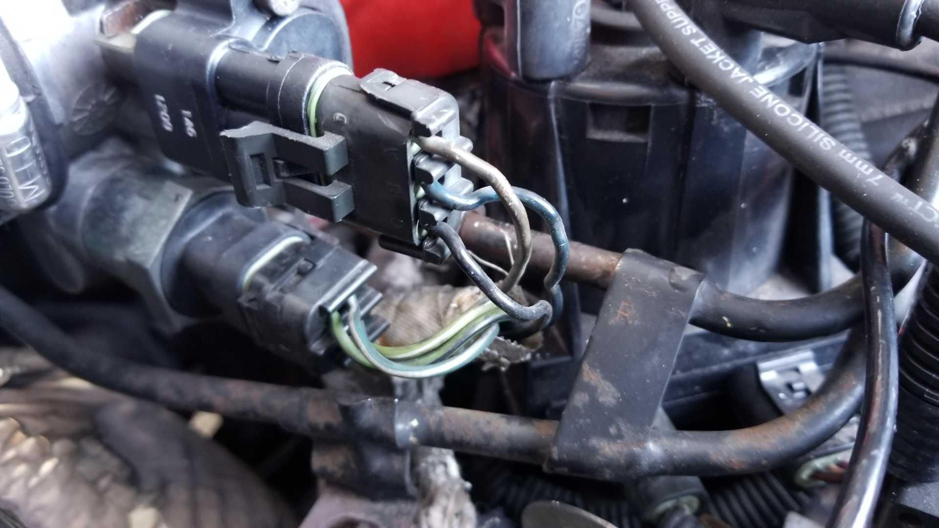
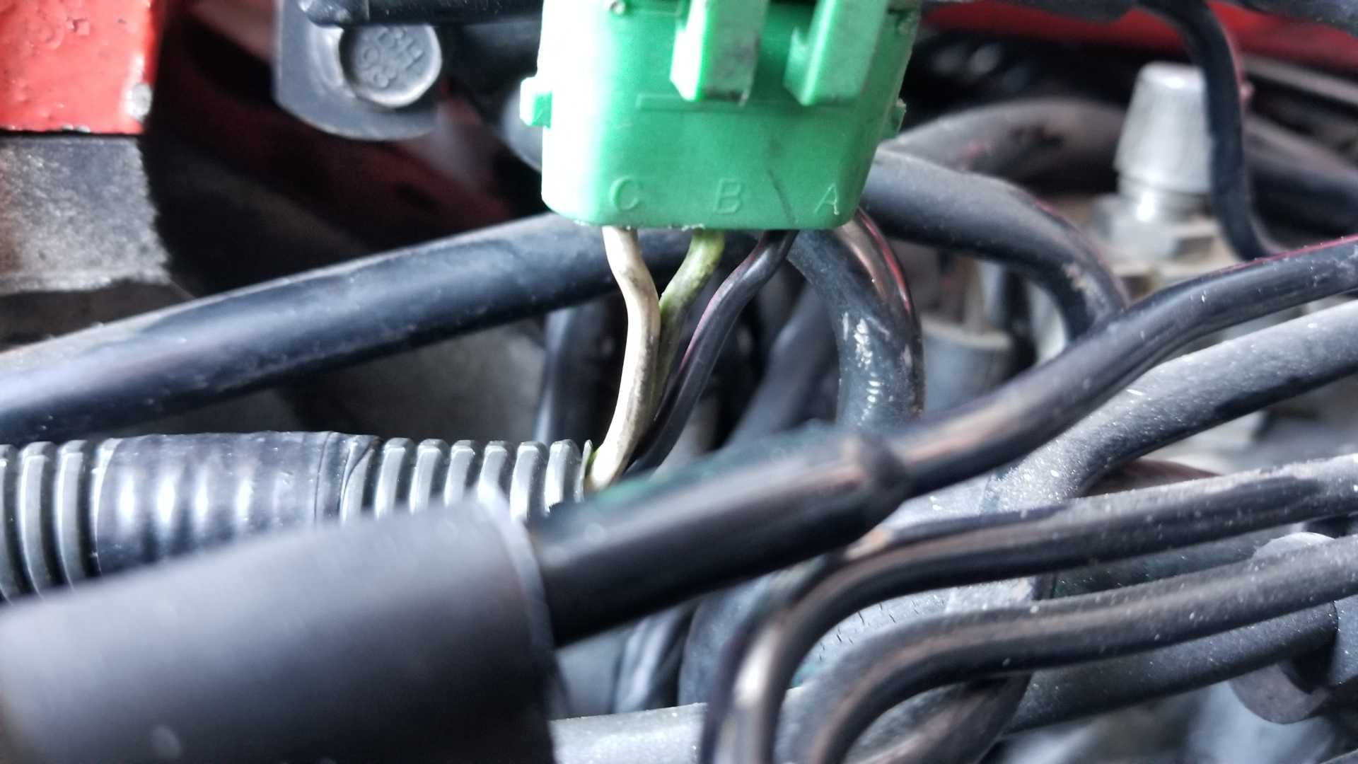
Assuming the connectors/wires are the problem, TFS has the TPS connectors for $19.95, Rock Auto has cheaper ones for $6.64 and AC Delco for $16.58. Is there any real difference, or is it worth the higher price for AC Delco?
|
|
|
|
Raydar
|
FEB 25, 04:57 PM
|
|
|
For those connectors, Rockauto would probably be fine. Pretty sure I've bought several connectors through them.
|
|
|
|