
 
     |
| TPI into an 84 SE (Page 2/4) |

|
rubyredfiero
|
MAR 14, 07:19 PM
|
|
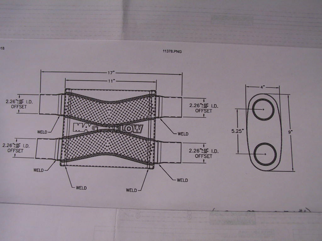
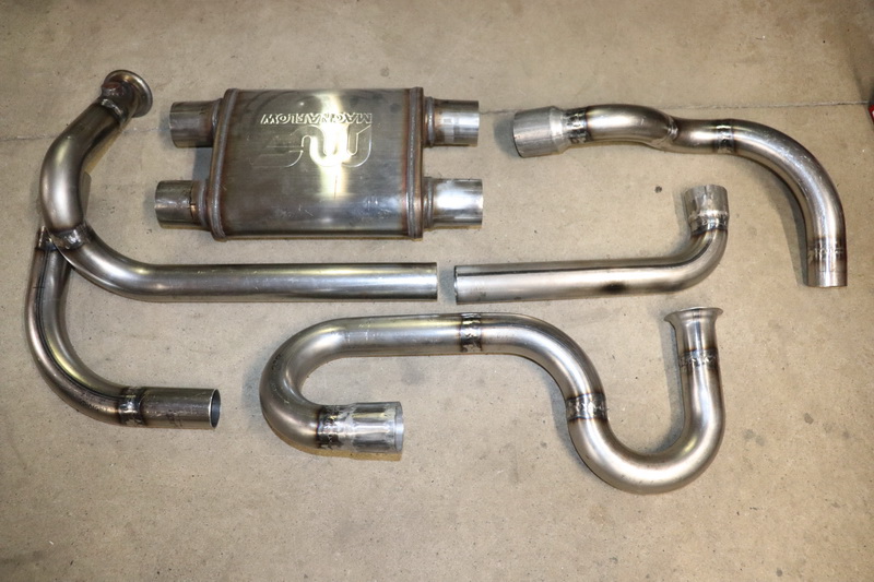
pmbrenelle - No I have not tried it in the car (still on the road) and that's why all the pipes are tack welded. But having said that, I mocked up the walls including the heat shields along pics from my another v8 I did in an 87. I should have more clearance in this one than I did with dual mufflers in the 87. That muffler is 4" x 9" x 11" for the body. I don't know how it's going to sound. Once it's fitted I will remove the bends and finish tigging all the joints. After measuring a stock V6 exhaust, there's actually more clearance with my setup. But proof of the pudding will be in the mock up. That's not for a while yet.
This is the inside of the muffler
 [This message has been edited by rubyredfiero (edited 03-15-2019).]
|
|
|
|
rubyredfiero
|
MAR 16, 11:49 AM
|
|
Ok, as mentioned already the A/C system differs quite a lot. Here are the comparisons. Just a reminder, I want to keep the 84 C500 and C203, just do some mods as needed.
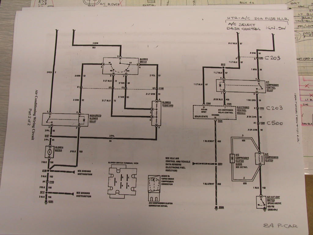
The 90-92 7730 A/C is wired without a "A/C Compressor Control Relay" for the compressor clutch.
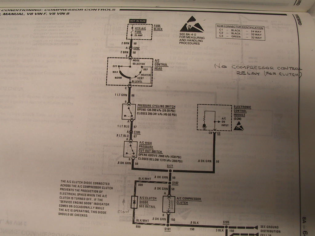
The 84 Fiero 1226156 A/C is wired with a "A/C Compressor Control Relay" for the compressor clutch.
The 84 A/C circuit.
Now if I read this right, when the button is pushed on the HVAC head on our dash and the key is in run, the circuit is completed thru C203 terminal 'D', which tells the ECM A/C was requested via C504 terminal '21'. The ECM supplies ground by connecting C505 '7' to C504 '12' (ground).
When the relay coil is energized via terminals 'A' and 'C', the relay's internal switch is made, which completes the circuit via C203 'N', relay terminals 'E' and 'B', C203 'K', C500 'A1', the compressor clutch and finally the A/C Cut-out Switch. Phew, I hope I got that right.
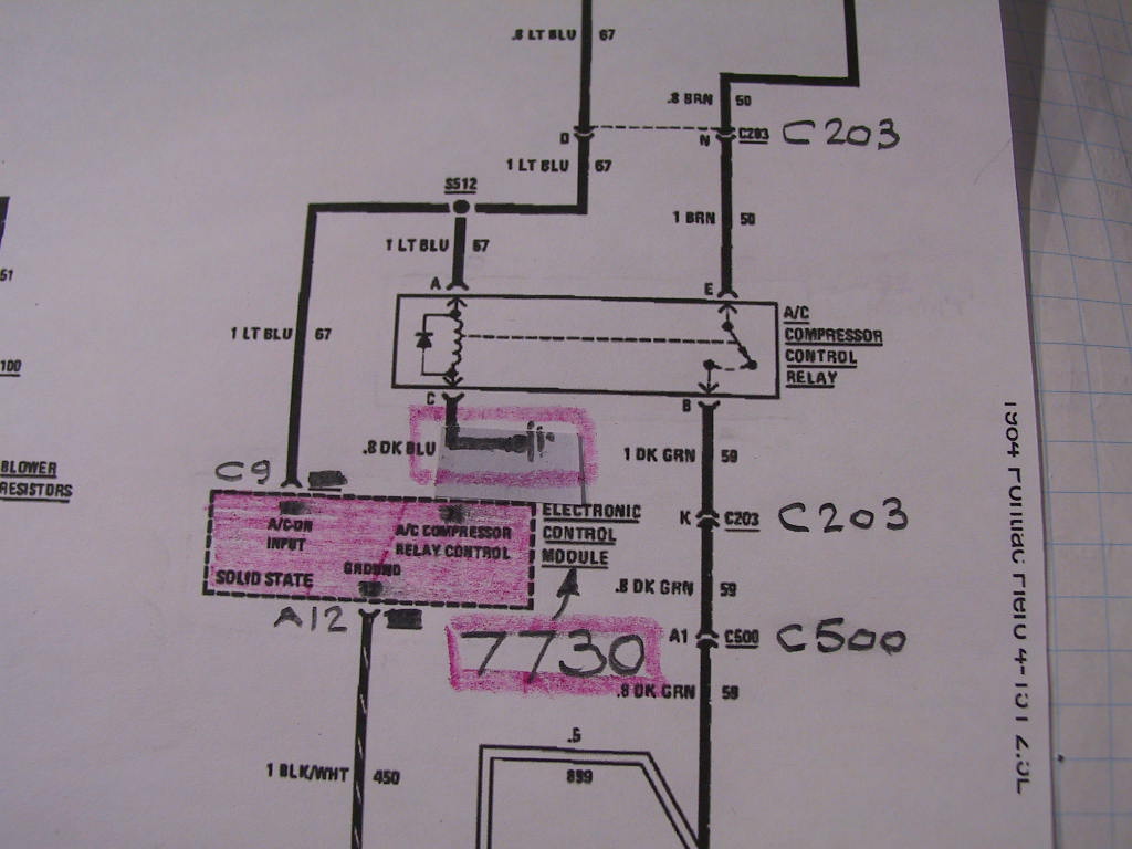
The 7730 circuit.
As I study the schematic, there is no place to attach the dark blue wire from the 84 ECM C505 '7'. Since all the ECM supplies the ground I will run the dark blue wire to ground. That circuit will be completed when the button up front is pushed. The red shaded are is the modification.
Please review my methodology and correct me or point out what I missed.
Thanks fellows.
|
|
|
|
rubyredfiero
|
MAR 18, 11:25 AM
|
|
I want to send a special thanks to BLOOZBERRY who pm'd me offering any assistance I may need. I already received some schematic info he used when he did his swap that applies to my project. I will first inquire on the forum for peeps to peruse, then if no one responds I will pm individuals for much needed assistance.
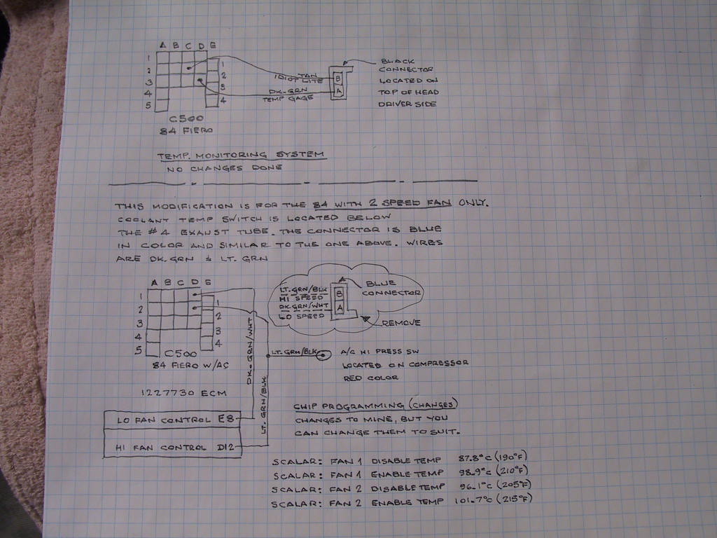
Having said (wrote) that, I'm surprised there were no comments on my a/c post. I will now show you what I did for my cooling system.
This applies to 84 Fieros with A/C and 2 SPEED rad fan. This is what I did and if you decide to use it, I will not be responsible for the accuracy and you are using my info at your own risk. The schematic is self explanatory especially the "CHIP PROGRAMMING (changes)" which is required to complete my swap.
I hope someone responds to this. Thanks.
|
|
|
|
rubyredfiero
|
APR 01, 11:41 AM
|
|
This is what I did for fuses to supply INJ 1 and INJ 2 power, and ECM power.
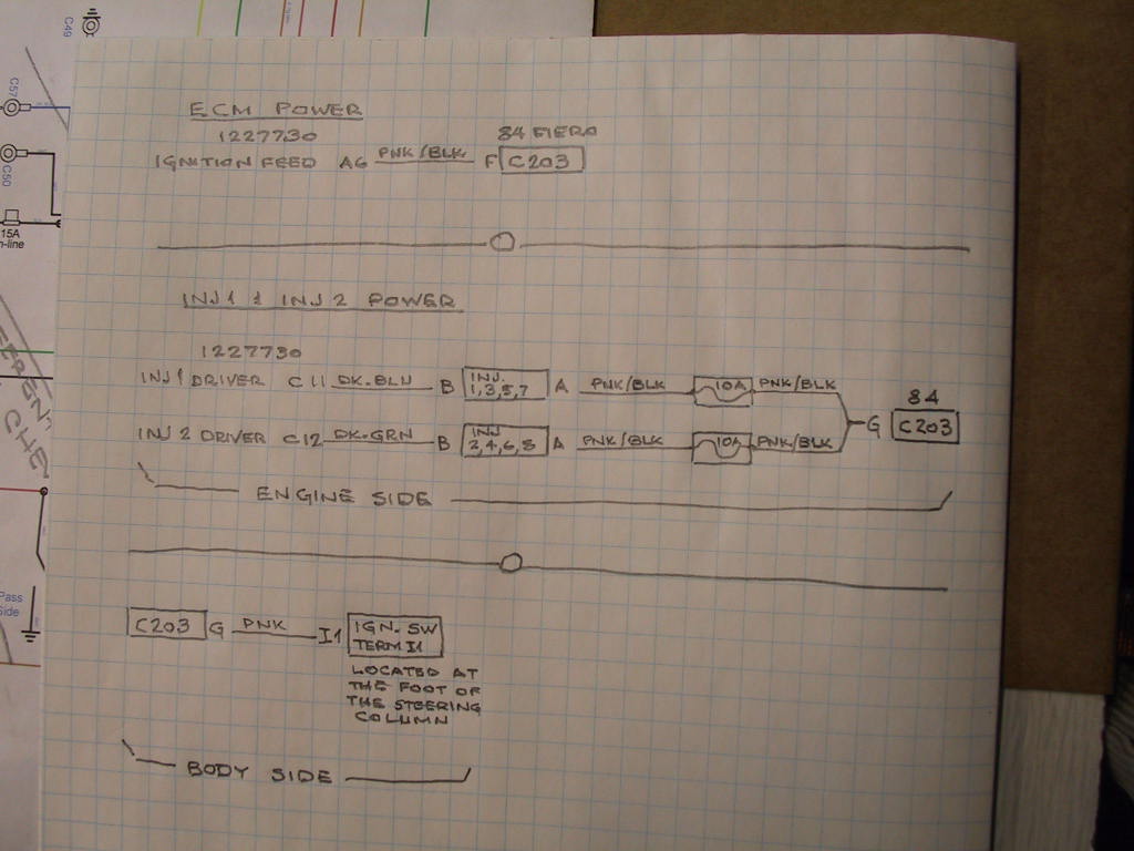
ECM power feed.
The 84 fuse box has Fuse #1 for the ECM power feed. Connector C203 Terminal "F" has the wire Pnk/Blk that I connected to ECM 7730 pin "A6" for the ECM power feed.
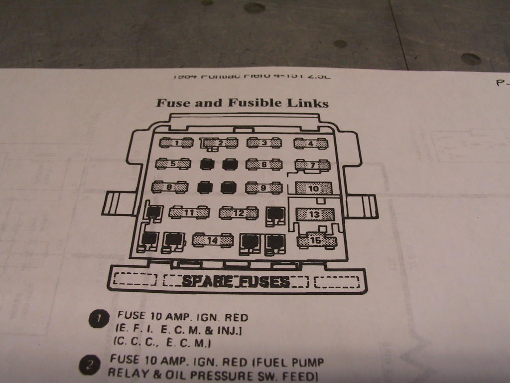
INJ 1 and INJ 2 power.
If you look at the pic of the fuse box, fuse locations between #5 and #6 is blank, so is between #8 and #9. There are no terminals or wires at the back of the fuse box to insert a fuse.
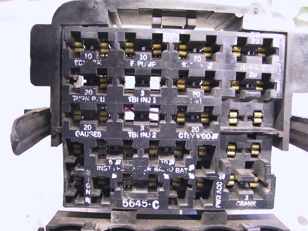
In the 84, C203 'G' is blank. So I spliced a 12Ga Pnk wire from the ignition switch (white switch a the bottom of the column) pink wire at terminal I1 (ign #1) to the body side C203 'G' using wires with their respective terminals from donor harnesses. From the engine side C203 'G' I spliced 2 inline fuses. One for each, inj 1 and inj 2. Then ran one fused wire to ECM 7730 'C11' for INJ1 and the other fused wire to ECM 7730 'C12" for INJ2.
It sure would be nice to see some feedback.
Thanks.
|
|
|
|
mafv8
|
APR 01, 06:08 PM
|
|
|
Sorry electricals not my thing, but I always enjoy a good build, especially an 84 with a SBC! ------------------
84SE, aero body, 4 speed and an injected 355 V8
|
|
|
|
pmbrunelle
|
APR 02, 06:42 PM
|
|
Nothing wiring-wise looks too crazy, though I do have constructive criticism (you did ask for feedback).
Pnk wire G is not fused according to best practices.
Normally, wires are fused as far upstream as possible, to protect against shorts to ground along the length of the wire. Fuses only protect the portion of the wire that lies downstream of the fuse; the upstream part is not protected. You presently have a long run that is unprotected against shorts.
Therefore, it is recommended that you add a fuse inline with Pnk wire G, as close as practical to the ignition switch.
The fuse shall be sized (ampere rating, see automotive chassis wiring ampacity tables such as https://www.littelfuse.com/...lfuse_fuseology.pdf) to blow at a current below the current that would cause the 12-gauge wire to smolder and catch the car on fire.
If you think the resulting fuse rating will cause nuisance blowing, that just means you undersized the wire.
|
|
|
|
rubyredfiero
|
APR 03, 06:00 PM
|
|
pmbrunelle - Thanks for the response.
I followed the pink wire that I will be splicing to, by referring to FSM for the 84 Fiero. That wire starts at the 'BAT' terminal on the starter, immediately through fuselink A red wire, to C500 terminal 'E4' all the way to the front to splice 'S206', then to the IGN switch terminal 'B3'. When the switch is crank/run it connects 'B3' to 'I1' (eye1). From IGN switch 'I1' on, it's pink through C500 'E3' to the coil's gray connector terminal 'B'. Now unless I missed something, that pink wire runs from the IGN switch all the way to the coil without a fuse in between. Instead of splicing into the coil's pink wire to avoid the extra demand on the wire, I chose to splice into the wire at the IGN switch 'I1" and run 2 in-line fuses for INJ 1 and INJ 2.
I hope I did not misread the FSM schematics.
|
|

|
2.5
|
APR 04, 11:52 AM
|
|
Very cool.
I've had a TPI swapped 87 GT for a few years now, from An 87 GTA. Its a 5 speed getrag. It was an old swap by someone else and I have got most of the lack of maintenance done, and fixed some things, improved / removed a few things, added a few. Driven it all over and made it home. I'll be watching your thread. For A/C this one has the V4 from the 4 cyl fiero on it. Good luck and keep on  [This message has been edited by 2.5 (edited 04-04-2019).]
|
|
|
|
rubyredfiero
|
JUN 22, 11:48 AM
|
|
Time for an update. It's been over a year since last posted here, so I figure I keep adding to it for continuity.
These are all the pipes tig welded, just before I assembled them on the motor.
|
|
|
|
rubyredfiero
|
JUN 22, 12:59 PM
|
|
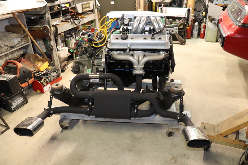
All the exhaust is assembled and painted with flat black VHT 1500*F header paint.
|
|
|
|