
 
     |
| airflow control in HVAC box (Page 2/3) |

|
JohnEStark
|
JUN 12, 11:43 AM
|
|
Hi guys, I just stumbled across this on one of the FB Fiero forums: (poster's name withheld by me) "Fieros have no motorized actuators for the heater system, that's New school tech, lol... All Fiero AC control valves are vacuum actuated, like pretty much every gm vehicle from the 60's thru the mid to late 80's... The GMT pickups were some of the first gm vehicles to get electronic actuators for the heater controls..."
Everyone else I have heard from talks electrical actuators. What's up?
------------------
John E Stark[This message has been edited by JohnEStark (edited 06-12-2018).]
|
|
|
|
pmbrunelle
|
JUN 12, 12:36 PM
|
|
|
That FB poster is wrong; the AC-equipped Fieros use electric actuators.
|
|

|
RWDPLZ
|
JUN 12, 02:50 PM
|
|
| quote | Originally posted by JohnEStark:
Hi guys, I just stumbled across this on one of the FB Fiero forums: (poster's name withheld by me) "Fieros have no motorized actuators for the heater system, that's New school tech, lol... All Fiero AC control valves are vacuum actuated, like pretty much every gm vehicle from the 60's thru the mid to late 80's... The GMT pickups were some of the first gm vehicles to get electronic actuators for the heater controls..."
Everyone else I have heard from talks electrical actuators. What's up?
|
|
Someone is an idiot. And yes if you're going to state it that matter-of-factly and be that wrong you deserve to be called an idiot. Fieros don't use ANY vacuum actuators in the HVAC system. The non-AC cars use two cables to open and close doors in the HVAC box to select between vent, heat, and defrost (top slider cable) and cool or hot (bottom slider cable); The AC cars use the push button head unit, which controls all the vents with actuators except the blend door, which uses a cable. No vacuum lines.
HVAC for AC equipped cars from the factory service manual
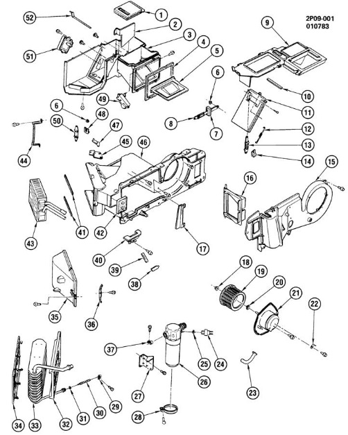
Item 49 - ACTUATOR, ELEC. AL.
Item 51 - ACTUATOR, ELEC. MODE
51:
49:
1984 Pontiac Fiero Factory Service Manual - Page 1B-4 AIR CONDITIONING
| quote |
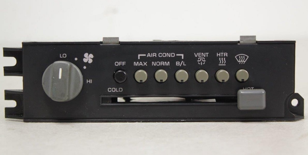
SYSTEM COMPONENTS-CONTROL
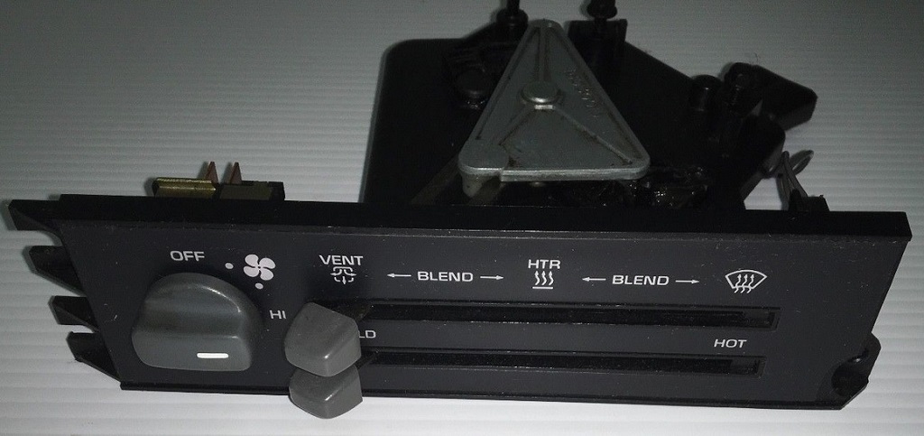
Controller
The operation of the A/C system is controlled by the switches and the lever on the control head. The compressor clutch and blower are connected electrically to the control head by a wiring harness. The blower circuit is open in the off mode and air flow is provided by the four blower speeds available in the remaining modes. Cooled and dehumidified air is available in the max, normal, bi-level and defrost modes.
Temperature is controlled by the position of the temperature lever on the control head. A self-adjusting cable connects this lever to the temperature valve which controls air flow through the heater core. As the temperature lever is cycled through its range of travel, a sliding clip on the cable at the temperature valve connection will assume a position assuring that the temperature valve will seat in both extreme positions. Temperature valve position is independent of mode selection. The temperature cable attaches to the top side of the air conditioning module. The systems fresh air valve and heater/defrost valve are operated electrically, thereby eliminating the need for vacuum control valves and lines |
|
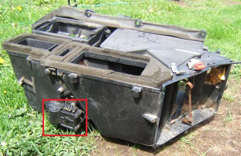
Heater Only Controller - Note only electrical connectors for the fan speed switch and a 2 pin connector for face illumination, and cable attachment points
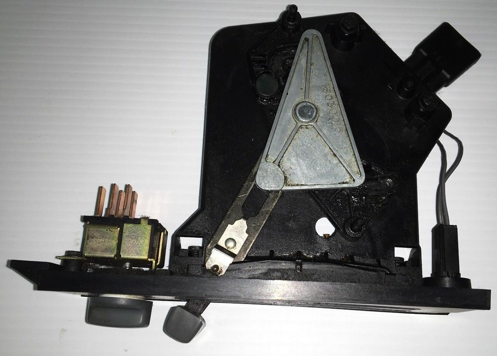
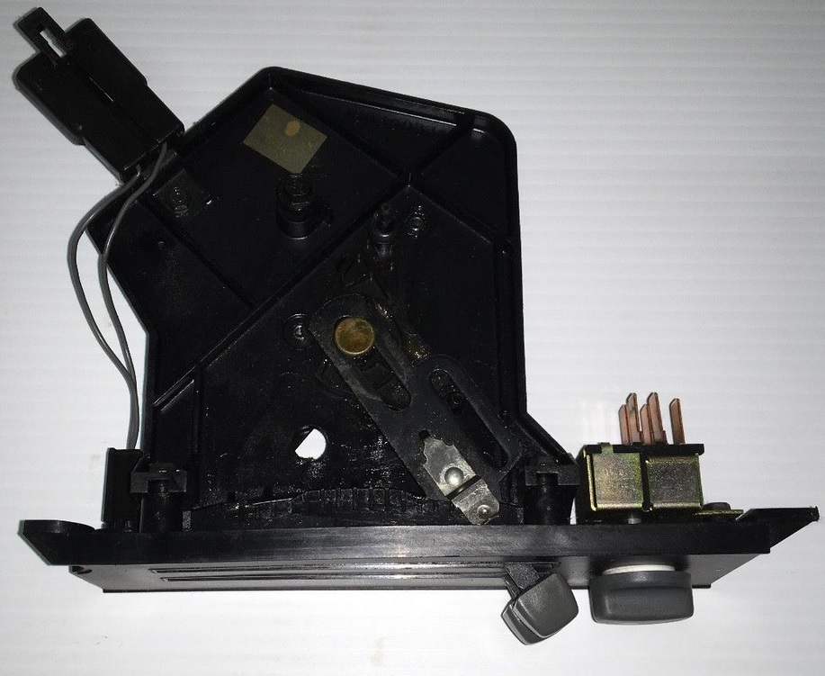
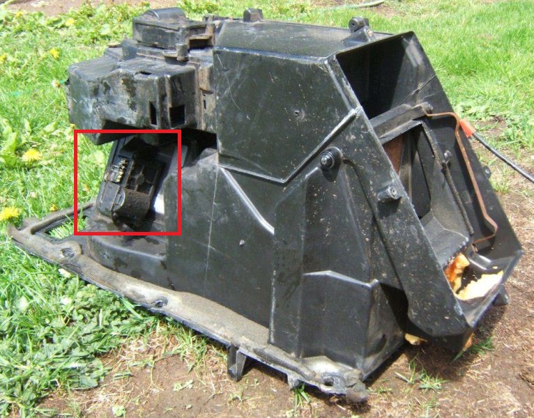
A/C controller - a single cable attachment point for the blend door, a large electrical connector, and the same smaller connector for the fan speed switch
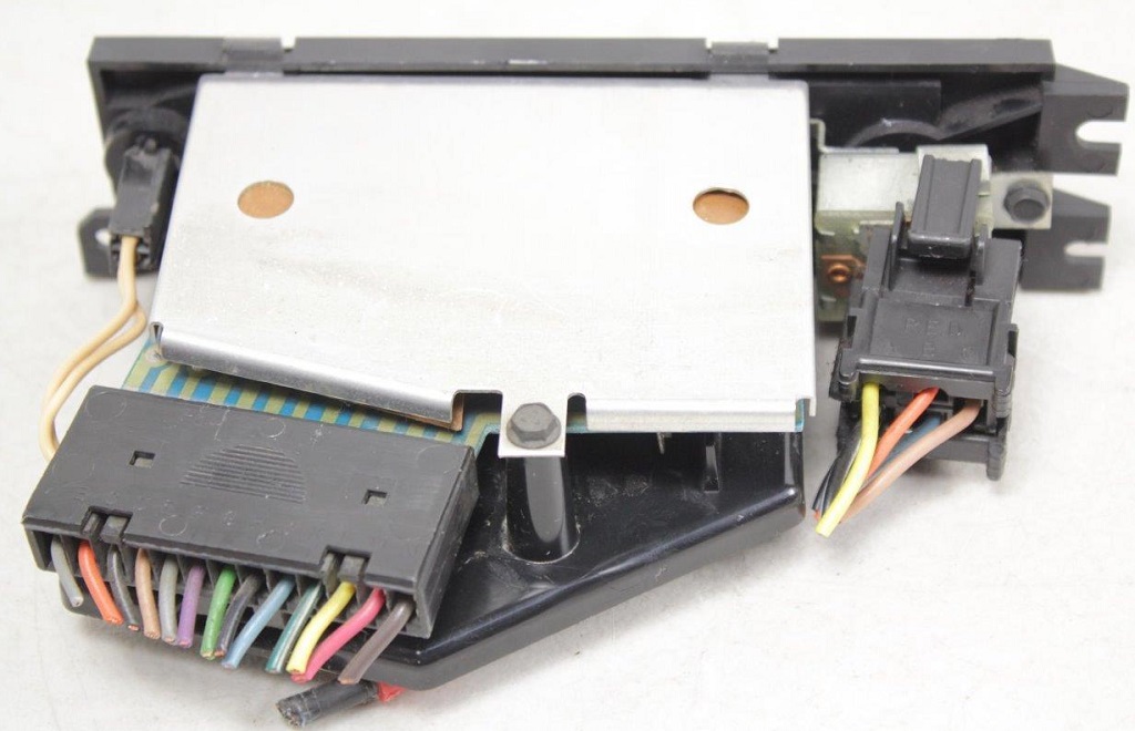
No vacuum lines, all cable and electronic.
|
|
|
|
JohnEStark
|
JUN 12, 03:44 PM
|
|
RWDPLZ: This is awesome support for what I am facing. On Saturday I'll have my tablet computer set to this thread next to my wrenches while I start the process of disassembly for diagnosis/repair.
I am fairly confident the blend door actuators are not working, but why? and what will I need to do to make them work?
Any advise on how to get to them? how to test them? Your pics show me what I am looking for, but I feel kind of like Indiana Jones at the door of the Temple of Doom! ------------------
John E Stark
|
|
|
|
RWDPLZ
|
JUN 12, 04:39 PM
|
|
Here's the actual airflow diagram
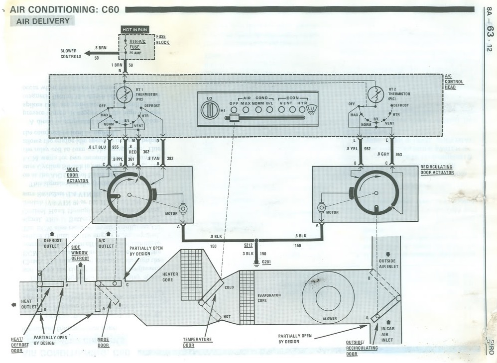
The Mode Door Actuator is the one that controls when air comes out of particular vents, Item 51 in the exploded diagram above. It's right behind the radio.
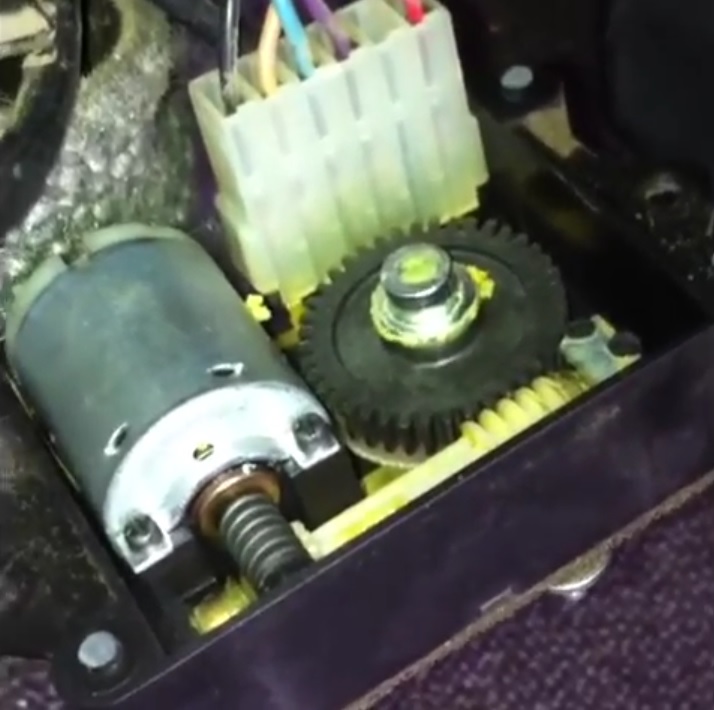
Here's a video showing where it is and how it works:
Try putting your hand on it while you press the different control head buttons and see if you can feel the motor and gears moving. If not try unplugging it and cleaning the wiring terminals at the actuator and connector.
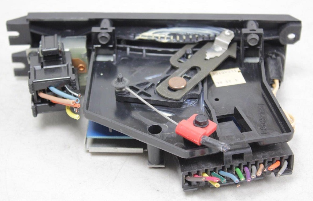
Actuator internals
|
|
|
|
br1anstorm
|
JUN 12, 05:34 PM
|
|
Only three things to say.....
1) RWDPLZ's posts - complete with pics, diagrams, video and crystal clear advice - are awesomely good. Great respect! That post (or this thread) should be made a sticky or put into a tutorial section;
2) I wish I had a spare HVAC assembly out on my lawn to experiment with and explore!
3) It's certainly looks like a royal pain in the a** to access, maintain or repair/replace those motors, actuators, levers and flaps. I'm just praying to the god of all automobiles that the control mechanisms in my own Fiero carry on working (more or less well) for a while longer......[This message has been edited by br1anstorm (edited 06-12-2018).]
|
|

|
JohnEStark
|
JUN 12, 08:17 PM
|
|
Once again, super thank you to RWDPLZ!
You have already made my Saturday better and today is only Monday. I WILL post a project update after the work session.
|
|
|
|
JohnEStark
|
JUN 24, 08:43 PM
|
|
Saturday a week ago I took out the radio, the console cover and worked on the A/C blend door. The process took two days, the report can be short and sweet. I now have cold air coming out the dash vents.
Using "Ogre's"wiring diagram I determined the blend door actuator worked. I sanded and cleaned the contacts, I think it actually works, but with cold dash air working I'll leave the buttons alone until fall when A/C is not critical to enjoying the car.
Thanks again everyone, especially RWDPLZ and Ogre.
BTW, The center tunnel in the frame swallowed a 1/4 socket and a short 1/4 drive extension. Trying to get it back was 1/2 my total work time. Gave up and reassembled with it in there. To my surprise, there is no rattle!------------------
John E Stark
|
|
|
|
viperine
|
JUN 24, 11:40 PM
|
|
RWDPLZ, thank you so much for compiling this information here, I had battled with my 86 GT blowing in default mode (a little air out of every vent at once) for years now. It's nice to visually see the diagrams explaining every little detail and even nicer to know only one of the motors controls airflow direction!
Only one thing left to sort out: how to remove an entire HVAC box from a parts car. I tried like heck at a junkyard last year and I am really quick at dissecting Fieros, but this one stumped me, despite a very in-depth attempt at disconnecting anything I could see and reach.
The two pictures of the unit you posted still leave me wondering what was preventing it from full removal.
Thanks again, RWDPLZ!
|
|
|
|
theogre
|
JUN 25, 03:35 PM
|
|
RWDPLZ
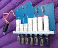
If you have this unit, can you count teeth on driven gears? (Drive gear on motor etc doesn't matter.)
 | | CLICK FOR FULL SIZE |
Guessing Big gear bit hard to count but think has 39 teeth, can't see small gear under motor so say 10. I get 390 rev's in on motor to 1 rev out. (seem Camera had problems compressing 1 part of big gear because very low contrast in one section.)
On the bottom of the big gear is the "switch" that stops for each selection.
Warning: Because of high gearing, If you jammed the output then even that "weak" motor can break whatever is weak. Is likely part of why used PTC Thermistors in the control board to reduce power to them as motors tries to draw more amps trying to prevent breaking. In short, Get PTC hot = more resistance. To limit motors they spike resistance and "shutdown." (Likely Faster the Breaker used in Gen1 HL motors.) Most Temp sensors in Engine are NTC types, hotter resistance drops w/ more even Ω curve.
 | | CLICK FOR FULL SIZE |
Not sure Thermistors are in Ground or Common side to the motors. Don't have real board layout now and FSM isn't exactly the same.
Plus If you have a AC Bulb dim/blown, Don't count thinking is just the bulb/socket... On top of dimmer problems, The wire here just pop out of the cold/weak solder joint to take pictures.
Won't surprise me if the board have other crap joints and part of why motor control "fix itself" just plugging in/out connections etc. Crap joints can kill the whole system or just 1 part of same. I didn't see markings to give away likely subcontractors that make the board like obvious maker and patents on chime unit that have same problem.
|
|
|
|