
 
     |
| The Getrag F23 Tutorial - By Emc209i (Page 24/28) |

|
fieroguru
|
SEP 07, 11:01 AM
|
|
| quote | Originally posted by pmbrunelle:
I have some questions; I'm thinking about doing an F23 install in my Fiero, which currently has a Muncie:
1.
When building transmission mounts, do I keep the bellhousing position in the same position as stock Fiero? The telescoping range of the axle tripods should work out okay if I do that?
2.
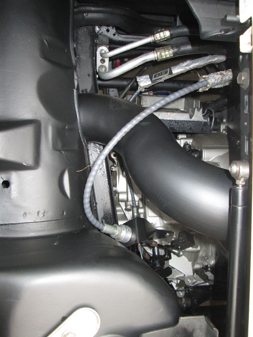
Is the fore-aft positioning of the differential similar to stock Fiero? I have a turbo oil drain line which passes a bit close to the RH tripod; I'm wondering if there could be a clearance issue with this transmission swap.
3.
My current exhaust crossover pipe would run above the plastic oil fill cap. Can/should this be blocked off somehow, perhaps with a metal plug? Is there an alternate method of filling the case to the correct level with oil if the plastic oil fill cap is not accessible? VSS hole maybe? Another hole?
4.
I was thinking of grinding teeth off the VSS reluctor wheel, so I could send a 4000 PPM signal (5 teeth should do it) to the instrument cluster (possibly with tweaks to account for the difference between variable reluctance and sine wave). How is the VSS reluctor wheel attached to the differential carrier? If I don't want to modify the stock reluctor, would it be feasible to make a new one as a laser-cut part?
5.
Do the Cavalier and Cobalt transmission cases (the non-bellhousing side) have the same shifter shaft angle / position? The more "horizontally inclined" the shifter shaft is, the more the shift cable will have to come from up high, complicating things. Is one case easier than the other with regards to building a shift linkage?
6.
If an HTOB spacer is used, will this not cause bending in the hydraulic lines which are also fixed to the case? How is this dealt with? |
|
1. The F23 seal sits proud of the bellhousing face about 1/4" further than all the other Fiero manuals, so there is something different with the width of offset of the differential, but lots of people keep the bellhousing placement side to side stock. The tripots have over +/- 1/2" (Probably closer to +/- 3/4") available range of motion, so 1/4" should be within the normal operational range. Also, with this being the passenger side with the longer axle, the tripot end will rotate less with suspension travel vs. the drivers side. It is always good to verify, but stock axles and stock bellhousing placement side to side should be fine.
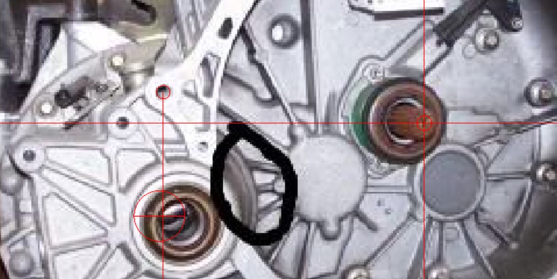
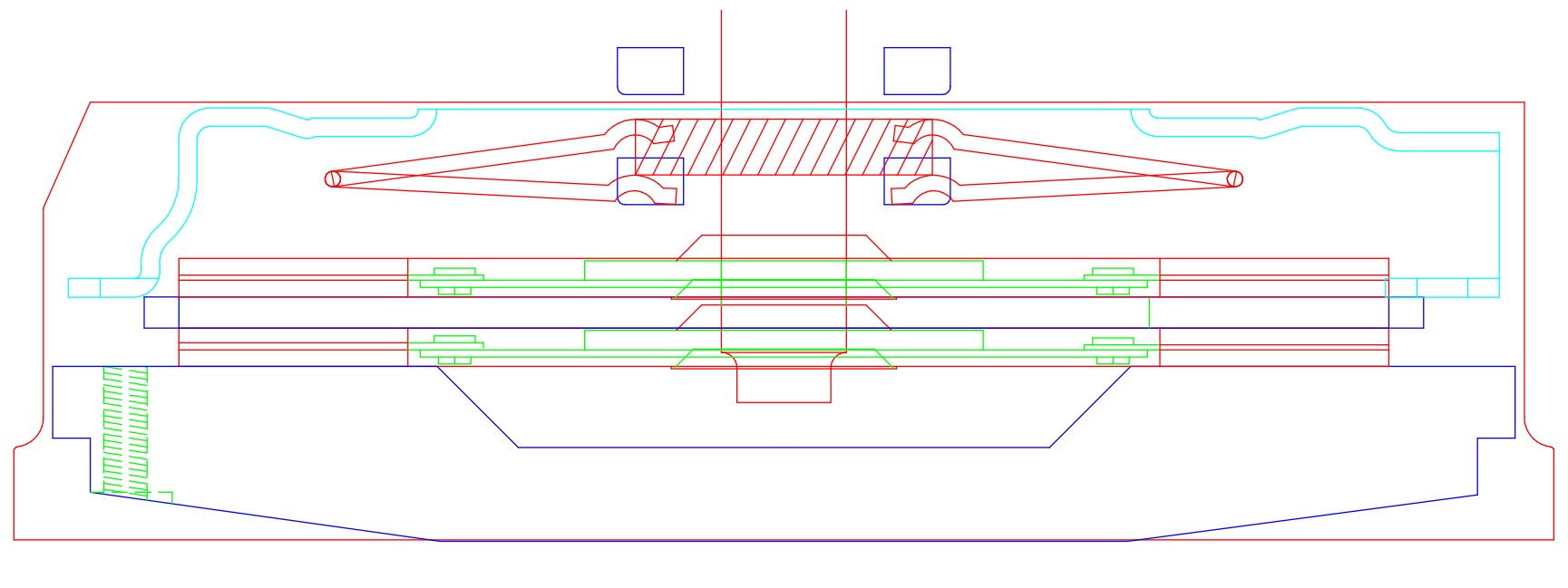
2. No. The axle centerline from the diff to the engine centerline will be closer and lower on the F23 vs. the 4 speed. This picture isn't 100% accurate due to the pic of the F23 being slightly angled and the one I had for the 4 speed was straight on. The red circle is the placement of the axe centerline on the 4spd and it was overlayed onto the F23 using the same rear bellhousing bolt hole reference.
3. No reason you couldn't fill at the VSS. If blocking off, need to verify where the vent is on the transmission. It might be the cap as the F23 doesn't have a visible vent line or vent cap off the shifter base (location of F40 vent).
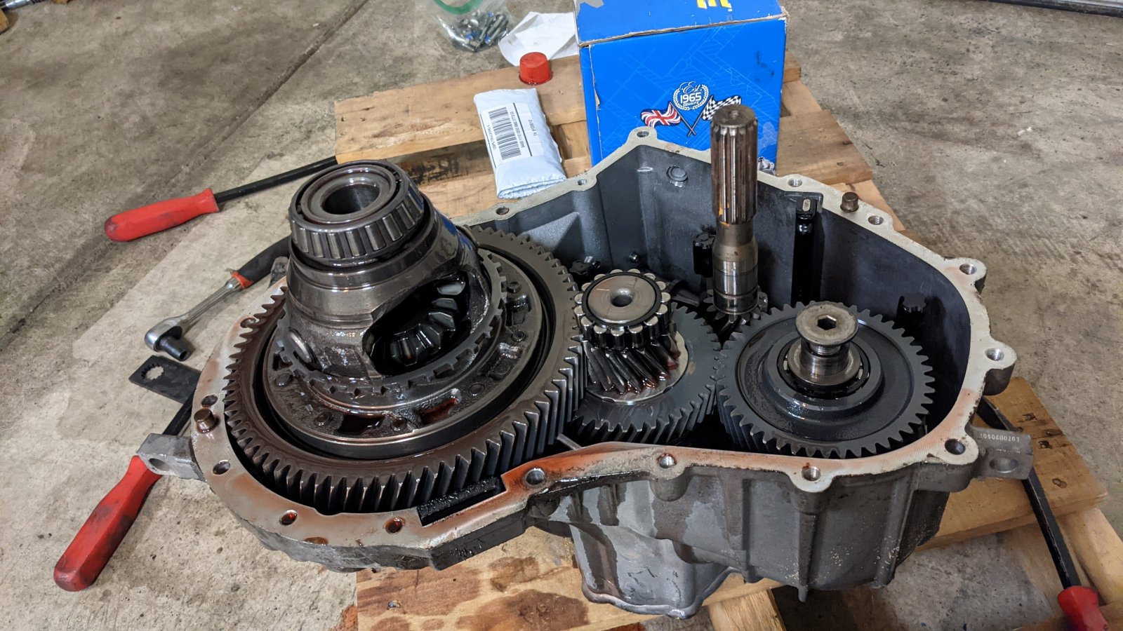
4. F23 VSS reads the teeth on a reluctor wheel that is pressed onto the rear carrier. It has a 24K pulse/mile, so the majority of the teeth will have to be removed to get to a 4K pulse/mile.
 ) )
5.Shift shaft inclination angle is the same across the entire F23 line. If you don't get a shifter modification kit, the shift cable will snake around the engine bay and come in by the strut tower.
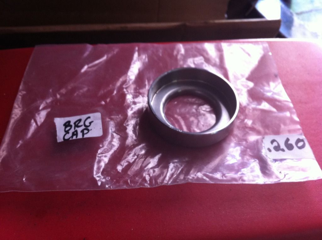
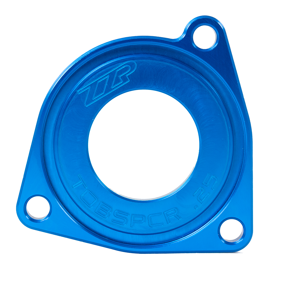
6. HYOB spacers come in 2 flavors. 1 is typically installed on the nose of the throwout bearing, extending its length. This one doesn't change the location of the hydraulic fitting. The 2nd style is a spacer behind the body of the HTOB. When this 2nd style is used, the lines pass through the hole about 1/8" more, but isn't normally any issue.
You didn't mention it, but there is a very good chance your current pressure plate could interfere with the differential bearing bosses inside the transmission, so you might want to factor in the cost of a new clutch as well if you go F23.
|
|
|
|
pmbrunelle
|
SEP 07, 12:54 PM
|
|
| quote | Originally posted by Trinten:
Those are some great questions. Most of which I can't answer, but I can try to get a hold of emc209i and ask him if he could provide the answers.
What engine swap did you do?
I would not recommend taking apart the transmission to grind off any teeth. That transmission is REALLY finnicky with coming apart and going together, even with the Kent-Moore toolkit, which has this "template" that holds various parts in the right relationship as you put things together. Not to mention if you start grinding off teeth, the internal balancing would be affected, no matter how small. To fix the VSS, I would suggest getting the Dakota Digital adapter and go with that.
If the crossover is blocking the cap, I would suggest looking into modifying the cross over. I think any other ports to try to fill the transmission would be slow and challenging.
I don't think the spacer will cause any issues with the lines, or I can't imagine how it does? It's only impacting the clutch and PP engagement by "adding" some length to the HTOB 'reach'.
There is a method for doing all the measuring for that, definitely something you want to do before you get the spacer. On Mike's initial swap using my old F23, he used the HTOB with the same spacer - no issues. On the next one he installed, which was out of a different year car, something was just different enough that he either didn't need the spacer at all, or he needed a thinner one. |
|
I don't have a swap; I have a mostly stock turbo V6. More details in build thread:
https://www.fiero.nl/forum/Forum2/HTML/142133.html
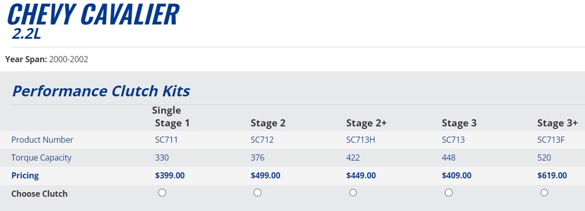
I would like to keep the Fiero Muncie Spec 3+ clutch that I already have, since it was a bit pricey and is still good, but if I have to change it, I will.
I think the car was making about 227 whp, so I'm surprised that I broke a Fiero transmission. I didn't baby the car, but I don't think I was abusive either. I was lucky that I broke the 3rd gear near home; I was able to limp home in 2nd. I think that the F23 will be more robust and give me peace of mind, especially when I drive far away from home.
I understand about the trickiness of servicing the F23. I might go for more of a homebrew electronic solution than the Dakota Digital. My friend has a Dakota Digital on his Fiero, and it doesn't seem very reliable. The speedo needle is sometimes twitchy; not smooth.
I think I would like the stock Cavalier ratios for my car, so I don't necessarily need to be swapping parts inside.
Crossover is tricky to modify without changing a bunch of stuff, so maybe I'll just fill the transmission with oil, and then install the crossover pipe. Transmission oil doesn't need to be changed often, so this aspect of the transmission install doesn't have to be perfect.
| quote | Originally posted by fieroguru:
1. The F23 seal sits proud of the bellhousing face about 1/4" further than all the other Fiero manuals, so there is something different with the width of offset of the differential, but lots of people keep the bellhousing placement side to side stock. The tripots have over +/- 1/2" (Probably closer to +/- 3/4") available range of motion, so 1/4" should be within the normal operational range. Also, with this being the passenger side with the longer axle, the tripot end will rotate less with suspension travel vs. the drivers side. It is always good to verify, but stock axles and stock bellhousing placement side to side should be fine.
2. No. The axle centerline from the diff to the engine centerline will be closer and lower on the F23 vs. the 4 speed. This picture isn't 100% accurate due to the pic of the F23 being slightly angled and the one I had for the 4 speed was straight on. The red circle is the placement of the axe centerline on the 4spd and it was overlayed onto the F23 using the same rear bellhousing bolt hole reference.
3. No reason you couldn't fill at the VSS. If blocking off, need to verify where the vent is on the transmission. It might be the cap as the F23 doesn't have a visible vent line or vent cap off the shifter base (location of F40 vent).
4. F23 VSS reads the teeth on a reluctor wheel that is pressed onto the rear carrier. It has a 24K pulse/mile, so the majority of the teeth will have to be removed to get to a 4K pulse/mile.
5.Shift shaft inclination angle is the same across the entire F23 line. If you don't get a shifter modification kit, the shift cable will snake around the engine bay and come in by the strut tower.
6. HYOB spacers come in 2 flavors. 1 is typically installed on the nose of the throwout bearing, extending its length. This one doesn't change the location of the hydraulic fitting. The 2nd style is a spacer behind the body of the HTOB. When this 2nd style is used, the lines pass through the hole about 1/8" more, but isn't normally any issue.
You didn't mention it, but there is a very good chance your current pressure plate could interfere with the differential bearing bosses inside the transmission, so you might want to factor in the cost of a new clutch as well if you go F23. |
|
Did you already have that CAD drawing done, or did you just prepare it for me? Thanks either way.
The diif being more forwards is not good for clearance, but lower helps me, so I think it will work with my existing turbo drain.
The F23 fill cap was referred to as the vent in the GM service video that I watched on youtube, so I'll need it, unless I install another vent elsewhere.
Since the shift shaft inclination is the same for both F23s, I guess I don't have much reason to get a Cobalt case. I was thinking of re-clocking the shift lever (by cross-drilling a new roll pin hole in the shifter shaft) so the cables could approach from a more straight-in direction.
Now I understand about the HTOB spacers.
If I can't get my existing pressure plate to fit, then I guess that the solution is to get a clutch for the F23 Cavalier? Is the bellhousing-to-flywheel distance the same between the Fiero V6 and Cavalier 2.2?
|
|
|
|
fieroguru
|
SEP 07, 10:51 PM
|
|
| quote | Originally posted by pmbrunelle:
Did you already have that CAD drawing done, or did you just prepare it for me? Thanks either way.
If I can't get my existing pressure plate to fit, then I guess that the solution is to get a clutch for the F23 Cavalier? Is the bellhousing-to-flywheel distance the same between the Fiero V6 and Cavalier 2.2? |
|
I have use CAD weekly if not daily for close to 30 years, so the drawing took less time than typing all the other responses, but it was the best way to show the issue.
The flywheel depth is very, very close across the entire GM FWD platform, so that isn't what causes the issue with the F23, but a too tall modified flywheel on a 3800 swap will absolutely cause it. Most of the stock clutches for the F23 are slightly smaller diameter than the Fiero 9 1/8". There are some 9 1/8" pressure plates that work, but it is hit and miss these days as the manufactures like to mix and match pressure plates on the same application. I would mock up yours and try it, you might get lucky. If it does interfere, you could explore what is interfering and see if it is something you can clearance away on a lathe.
|
|
|
|
pmbrunelle
|
SEP 08, 12:14 AM
|
|
Was the pressure plate to flywheel interface (number of bolts, thread size, bolt circle diameter, dowel pins if applicable) standardized among FWD GM cars?
In other words, will a Cavalier pressure plate bolt to a Fiero flywheel, or is that likely to require machining?
|
|
|
|
fieroguru
|
SEP 08, 10:47 AM
|
|
| quote | Originally posted by pmbrunelle:
Was the pressure plate to flywheel interface (number of bolts, thread size, bolt circle diameter, dowel pins if applicable) standardized among FWD GM cars?
In other words, will a Cavalier pressure plate bolt to a Fiero flywheel, or is that likely to require machining? |
|
I believe the 2002 Cavalier bolt spacing and threads are the same as typical fiero.
Rock auto lists a 9" pressure plate as well as a 8 1/2" pressure plate, but their flywheels don't specify a specific clutch setup. The flywheels also show an equally spaced 6 bolt pattern at the limits of the 142t flywheel, which is what the fiero has as well.
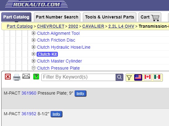
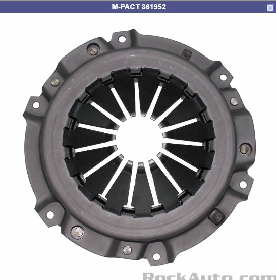
You can also see that the 8.5" pressure plate has protruding tabs to pick up the pressure plate bolt holes.
Here is the 9" one for reference:
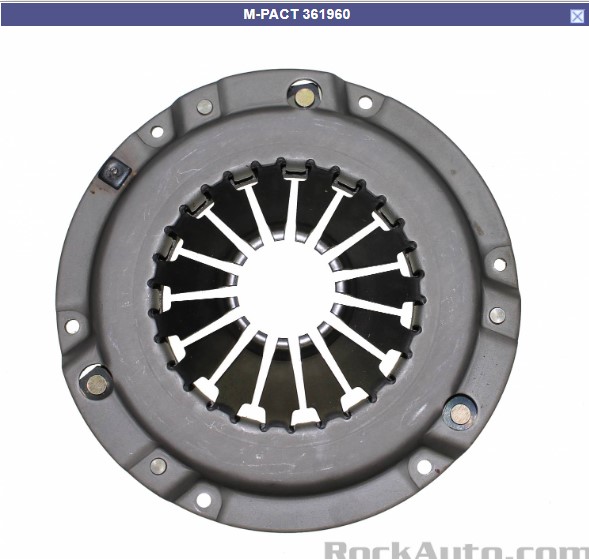
The big thing is to make sure the pressure plate clutch ring is large enough for your clutch.
It might be worth calling spec and asking about the differences between your Spec Stage 3+ and the Cavalier/F23 one:
|
|
|
|
pmbrunelle
|
SEP 09, 08:01 AM
|
|
It looks like the 8-1/2" clutch was a cost-saving project that popped up at some time, likely not coming from some technical requirement.
********************************************************************************
| quote | Originally posted by fieroguru:
The flywheels also show an equally spaced 6 bolt pattern at the limits of the 142t flywheel, which is what the fiero has as well.
|
|
I checked on Rockauto, and the same flywheel is sold for both 88 2.8 Fiero and 2.2 F23 Cavalier applications.[This message has been edited by pmbrunelle (edited 09-09-2024).]
|
|
|
|
pmbrunelle
|
SEP 16, 07:27 PM
|
|
| quote | Originally posted by fieroguru:
It does. Take the total range of motion of the HTOB (say it is 1.5") and you want it setup with 2/3's (or 1") of the available travel to the front for disengagement, and 1/3 (1/2") for it to retract backwards as the clutch disk wears. |
|
Where does the 1/3 - 2/3 rule come from? Is this simply a "rule of thumb" that seems to work?
****************************************
It seems to me that the available disengagement_travel must be slightly greater than the fluid volume pushed by the master cylinder, divided by the surface area of the slave cylinder.
Where:
HTOB_total_travel = HTOB_retracted_position - HTOB_extended_position
It follows that:
wear_travel = HTOB_total_travel - disengagement_travel
In my understanding, disengagement_travel is a requirement that is independent of HTOB_total_travel, so I do not understand.
|
|
|
|
fieroguru
|
SEP 16, 10:41 PM
|
|
| quote | Originally posted by pmbrunelle:
Where does the 1/3 - 2/3 rule come from? Is this simply a "rule of thumb" that seems to work?
****************************************
It seems to me that the available disengagement_travel must be slightly greater than the fluid volume pushed by the master cylinder, divided by the surface area of the slave cylinder.
Where:
HTOB_total_travel = HTOB_retracted_position - HTOB_extended_position
It follows that:
wear_travel = HTOB_total_travel - disengagement_travel
In my understanding, disengagement_travel is a requirement that is independent of HTOB_total_travel, so I do not understand. |
|
You are missing several critical things:
1. Release distance is not consistent from clutch to clutch, pressure plate to pressure plate.
2. Depth of the pressure plate fingers is not consistent from clutch to clutch/pressure plate to pressure plate.
3. Excess range of motion for release will help when there are issues with bleeding or parts wear and hydraulic performance suffers - you don't want to have the bare minimum of release travel.
4. Balancing the packaging of the flywheel, spline engagement on the clutch disks, and pressure plate clearance to the bellhousing will likely be larger drivers of the the precise placement of the HTOB range of motion. But if you over extend it, you will kill it and be pulling it all apart again.
Take these into account over several combinations and you start to see the sweet spot is between 1/4 to 1/3 of the HTOB range of motion for wear, and the rest for clutch release. It will maximize the life of the clutch while allowing proper function across a vast mix of clutch combos.
When I had to make a new flywheel for the twin disc clutch for the LS4/F40 swap, it was a super tight fit with bellhousing clearance, spline engagement, and keeping the HTOB happy, but it all works perfectly.
|
|
|
|
fieroguru
|
SEP 17, 07:08 AM
|
|
If you want to detail out your specific clutch and pressure plate finger range of motion:
Install the clutch and pressure plate on the flywheel and measure the height/depth of the pressure plate fingers from the face of the bellhousing flange on the engine.
Remove the pressure plate and clutch, make a shim about 0.90" to cover the fiction surface of the clutch, reinstall the clutch, shim and pressure plate. Measure the pressure plate finger height/depth (it will ne numerically lower) - Consider this the minimum extension needed to release the clutch (many mfg look for about 0.60", but the fingers will flex some as the clutch is released, which is why I recommend using 0.90").
Remove the pressure plate and clutch, measure the thickness of the rivets holding the pad material to the disk. Install just the pressure plate with shims the thickness of the rivets. Measure the pressure plate finger height/depth (this will be a numerically higher number) - this will establish the maximum amount of wear distance needed.
Now you have the key heights/depths of the pressure plate fingers for your specific clutch and pressure plate. You can overlay the HTOB range of motion and see if it can accommodate all 3 without needing a spacer.
|
|
|
|
pmbrunelle
|
OCT 11, 08:30 AM
|
|
How is the reverse light switch meant to be installed on the Getrag F23?
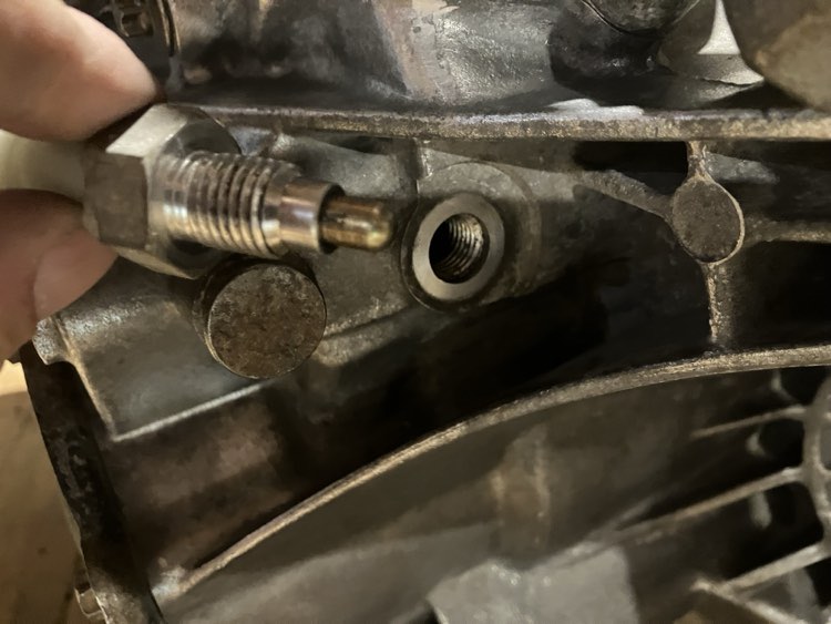
I see no sealant on the threads, no washer, no specific method to ensure sealing of the oil.
The body of the switch is aluminium. Is the aluminium meant to act as a cheap crush washer that squeezes against the face of the transmission?
|
|
|
|