I'm going to email him, but so everyone can benefit, here are his instructions:
3 Wire Connector: 1. Pink- Switched 12V from fuse block (I use the one behind the stereo) 2. Black- Trunk release, black on 84, gray/black on 85+, at the trunk release switch 3. Black/White- Leave disconnected (ground to program remotes)
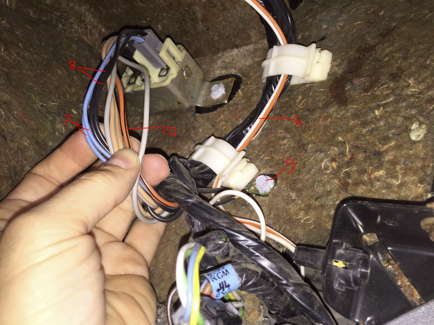
8 Wire Connector: 4. Red/Black- Not used 5. Orange/Black- Not used 6. White- Connect to the white wire going to the light 7. Gray- light blue wires 8. Tan- Splice both together, black wires on door lock/unlock connector next to light 9. Black- Ground screw for power lock relay 10. Orange- Orange/Black wire at power lock relay
Here is a photo of the area, with what I think are the correct wires for the 8 Wire Connector:
I know this is an old thread, but just want to throw something out to possibly help the next guy.
For me and my 1986 SE, the white wire on the 8-wire connector could not be run to the white wire of the light -- it kept blowing the dome light fuse and the RKE wouldn't work. Turns out, the RKE is sending a ground signal to turn on the light, and that white wire on the courtesy light is a 12v. For me, the white wire on the RKE had to be run to the orange/white wire on the closest courtesy light, which was the ground.
Finally getting around to installing this. I got it last year. Have a few questions.
White: 8 Pin Connector - Connecter to white wire on Foot Well light. ^ is this a ground? or 12 volt? Cuz if its a ground why not just connect to the black frame ground?
Pink: 3 Wire Connector - "Switched 12V from fuse block (I use the one behind the stereo)" ^ So this is a 12 volt that only come on when you turn the key right?
Then that must mean the constant 12 volt is the WHITE WIRE on the FOOT WELL light?
Black/White: 3 Wire Connector - "Leave disconnected (ground to program remotes)" ^ Huh?? So do I need to ground this unit after turning the ign key to program the unit, then disconnect the wire?
Sorry guys. I never had a camaro so I'm not at all familiar with this system. Does anyone have key FOB programming instructions?
Once it’s all hooked up apply ground to the program wire and the locks will activate letting you know it is in learn mode. After it does, push a button on the remote to program it. Then disconnect the ground.
Once it’s all hooked up apply ground to the program wire and the locks will activate letting you know it is in learn mode. After it does, push a button on the remote to program it. Then disconnect the ground.
Ok so I can add a "program switch" to this wire?
How should I go about powering up the unit? Should I just wire the harness and plug the unit in, and connect the program wire? Or is there one last wire to connect?
ok so i wired everything up and plugged in the unit with the key off. I turned the key to ON, and then connected the program wire. The door locks activated, and I held down the unlock on both remotes. No response.
Ok got it now. I forgot to disconnect the program ground wire. Now it's up and running!
[This message has been edited by SP1200 (edited 03-18-2018).]
I disconnected the door lock relay, unscrewed the ground wire, cut (then reconnected) the door switch...and was able to pull the wire harness out the speaker hole. Made installation with the short pigtail easy for my back neck. Also NOTE. I did not need to connect to both of the BLACK and BLUE wires as they both meet up at the relay. So connecting to both seemed redundant.
[This message has been edited by SP1200 (edited 03-18-2018).]
I'm going to email him, but so everyone can benefit, here are his instructions:
3 Wire Connector: 1. Pink- Switched 12V from fuse block (I use the one behind the stereo) 2. Black- Trunk release, black on 84, gray/black on 85+, at the trunk release switch 3. Black/White- Leave disconnected (ground to program remotes)
8 Wire Connector: 4. Red/Black- Not used 5. Orange/Black- Not used 6. White- Connect to the white wire going to the light 7. Gray- light blue wires 8. Tan- Splice both together, black wires on door lock/unlock connector next to light 9. Black- Ground screw for power lock relay 10. Orange- Orange/Black wire at power lock relay
Here is a photo of the area, with what I think are the correct wires for the 8 Wire Connector:
I realize this is a very old topic and been stagnant for quite some time but I bought one of these packages many years ago and finally put in recently.
I wired the box up per the pic above and the instructions on the box when I got it (they match) and I am at the point of trying to program the fob and when I put the black/white wire to ground per instructions, I do not hear the door locks cycle.
Question: 1. Is there a way to bench test the box itself to make sure it is working? I was thinking of putting power and ground to power and ground pins per the wiring diagram and then grounding the program ground. I assume that I would see power come from the tan wires pin to be able to confirm the box is working?
I am trying to work back and see if there is a wiring issue (don't think so) or if the box is not working as it has sat for many years in my parts cupboard.
Thoughts anyone?
Thanks much Don
AH CRAP!!!!!!!! I just read the last post about not being able to get the door locks to pop and saw that I need to turn the key to on to program..... I am so oblivious to the obvious sometimes. I will try tonight and hopefully everything works fine and I can sheepishly walk away...... sigh.......
[This message has been edited by 355Fiero (edited 04-20-2023).]
OK, I plugged everything back in and grounded the black/white wire from the three pin plug and no door lock activation to show going into test mode. I have confirmed the large plug and small plug wiring again and still no love.
So the 12V switched in the 3 pin connector and the power that goes to the 8 pin plug from the relay power I assume. Wasn't sure about needing the other wires connected in some manner so if that is all, great and I will do that on the bench tonight and make sure I get the right pins from each plug so I don't toast it after all this..... And the grounds as well. Way easier to do that on the bench than crawled up under the dash. I am getting too old to contort that way....
Ok. I looked at the pins and mapped them out and hooked up the power and grounds per the pin map. Also added a pin lead from one of the tan pin leads and then grounded the 3 pin programming lead.
I assume that the tan output should show some power like 12v or something when grounding as that is what cycles.
No love. I am going to try the white light power lead as well now but really starting to think the module isn’t working any more.
Been a pile of years since I bought it so who knows what has happened in the mean time.
Almost ready to call this a bust and move on to the next item…


 And the grounds as well. Way easier to do that on the bench than crawled up under the dash. I am getting too old to contort that way....


