That looks awesome bud! Nice work It is pretty neat when an actual metal fab professional gets on these forums and is able to make the parts that we can all imagine, but don't have the skills or tools to make.
I love the ecotec motor. I have driven a few of them, including the boosted ones, and in hindsight I think that is an even better swap motor for Fieros than the 3800. Light, powerful, loves to rev, and tons of aftermarket support.
Since I need a dog bone to limit engine movement, I made a custom one. This will not be mounted in the stock Fiero location and it will reside down low. I'll use this hole for now. I will add a bracket later to create a double shear system.
On this end, I'll need to make a bracket.
Here's my design.
Off comes the engine and transaxle again so I can finish off the cradle. Gussets added here.
A notch for the AC compressor was required. No biggie.
Dog bone lower mounts.
Here's the cradle completely welded.
Shot of the AC compressor notch. I made it a little bigger purposely.
Then I decided to notch the frame slightly to allow clearance for the F23. Much better.
I will now take a break from welding and add primer and paint to the frame notch. Then it's off to sandblast the cradle and mounting brackets.
Your dogbone will be almost totally ineffective. It's too close to the axle centerline and where it attaches to the cradle it's perpendicular to the direction it needs to be going.
After sandblasting the cradle, I painted it to match the engine bay. Then I reinstalled the drivetrain.
Here's a few pictures of the clearance the Ecotec in a Fiero provides. Man, this is easy to work on.
I slightly shaved the bottom of three ribs on the F23 for additional trans to cradle clearance. I did leave some material but it's not that easy to see.
As you can see, the drain plug is still accessible. This will make maintenance easy.
The frame notch worked out well. Clearance is great but very difficult to see in this photo.
Then I decided to remove the springs from the struts and check for full suspension movement.
With the axles installed dry, and with no boots on, I checked travel on both full droop and compression.
At full compression, the passenger side axle just touches the dog bone. I'll address this next week.
Then I painted the PCM black and reinstalled.
Knowing that BMW also uses Getrag transmission's in their cars, finding a suitable clutch hose was easy. If you look at the top left, you can see the part number. (21 52 6 774 267)
Here is the original Cavalier clutch slave and its associated parts. I only need the bleeder, the piece in the middle.
This plugs perfectly into the BMW clutch flex line.
Then install back into the F23. It's a perfect fit and there's no other fittings needed.
As you can see in this picture, the protective sleeve is in the perfect position. This will protect the clutch line from rubbing on the frame. It's like it was meant to be.
Here it is zip tied to the bottom of the frame rail.
I filled the Rodney Dickman clutch master with fresh DOT 3 brake fluid and left the bleeder screw open. After a few minutes, I topped the reservoir up again as the fluid made its way through the line. I closed the bleeder and had my assistant pump the clutch pedal. Within only a few minutes, the system was bled and leak free. It was so easy, a cave man could do it. It's nice having one of my three pedals working.
Note: In my application, these components (RD clutch master and F23 slave cylinder) play well together. Other swaps, with F23 conversions, may need a spacer between the pressure plate and slave cylinder to prevent the slave from over-extending.
Knowing that BMW also uses Getrag transmission's in their cars, finding a suitable clutch hose was easy. If you look at the top left, you can see the part number. (21 52 6 774 267)
Here is the original Cavalier clutch slave and its associated parts. I only need the bleeder, the piece in the middle.
Do you have the part number for the F23 bleeder gizmo?
Will,
The bleeder is not available for purchase separately. It must be purchased as an assembly and comes with the components as seen in this photo. Should you need one, I have a used one that I can send you. The Dorman part number is: CM640069
[This message has been edited by Lunatic (edited 08-21-2016).]
Don't understand why this is not in the construction zone already.
Keep posting the updates, another one of the "great" build threads!
HAGO!
Thanks for the compliments Sage. Here's a little update for those following.
I kept busy by cleaning the throttle body.
Now that it's clean, I reinstalled onto the engine. While close to the firewall, there is still clearance to run a 90° elbow in this area.
The stock four cylinder throttle cable fits into the Ecotec throttle bracket. Woot woot.
Surprisingly, the stock throttle cable slid into place. I suppose I could've cut the end down slightly but I decided to leave it. I verified WOT (wide open throttle) by having an assistant depress the throttle in the car. The throttle blade opened to the max. It's like it was meant to be.
Since my car came with a pin switch to operate the trunk light, I didn't like the look of it. So I removed it. The newer cars came with the trunk switch in the latch/striker area. I liked the look of that better and found the appropriate switch. What I needed was a good ground to the release solenoid. I removed the harness and added a dedicated ground wire.
Then I drilled a hole in the firewall to pass this new trunk wire assembly into the cabin.
I'll have to clean this up and secure it.
I moved on to wiring the new trunk circuit as well. It sure is nice to have an operational trunk release and trunk ajar light working. With having said that, I was still missing the trunk light though. I decided against putting the stock trunk light bulb back into operation. That little sucker gets hot! With having a tackle box full of odds and ends, I decided to build an LED light assembly. I re-purposed a few things and here's what I came up with.
While it's difficult to take a photo of an LED light, I turned out the basement light and this is the best shot that I could come up with. If it's bright enough to light up the ceiling, it'll be good enough to shine light into my trunk.
A few remaining wiring tasks for my swap involved wiring up the BCM (body control module) and modifying the A/C circuit. Let's discuss the BCM first. The only circuit on the BCM that I was interested in was the interior light control. In this case, it softly dims the interior lighting after closing the doors, like many new cars do. It also puts the interior lights on a timer. This is a nice feature. For example, when cleaning the car and leaving the doors open, the BCM turns off the interior lights after a preset amount of time. I chose to wire in this feature only. The BCM I'm using is part number: 22682857. This is just a plain BCM and it didn't come with the key-less entry feature.
Since there were many places that I'd have to tap into, I chose to remove the dash. This BCM requires several points of power and these came from a few different circuits. Some require full time power while others need key-on or accessory power. The back side of the fuse panel was chosen for all my power taps. In this manner, all BCM circuits are protected by fuses.
After the primary battery, accessory power and ground was wired to the BCM, it was then time to redirect the power and return for the courtesy and dome lighting to the BCM.
Note: S (ex, S210) stands for a splice location in the harness and C (C200) stands for connector. I needed to cut the courtesy and reading light supply (orange wire) to make this work. 1) Follow the driver's side courtesy light (orange wire) to the S210 splice location in the harness and cut it leaving an inch or so before the connector. I chose to cut the wire on the “main harness” side.
2) Follow the orange wire coming from the dome/reading lights back to the C200 connector under the dash at the extreme left, upper forward corner. Cut this wire a few inches before it goes into the connector. Join the orange wire “going to the dome lights”, at the S210, together with the orange wire “going to the courtesy lights”. Attach another wire and run this to the blue connector, pin A10 (Inadvertent Power Control) on the BCM.
This now leaves two orange wires that were previously cut. Extend the orange wire, coming from the C200, (that used to feed the dome/reading lights), to the orange wire that previously fed the courtesy lights (S210 splice location). Join these two wires together and add another length of wire. This goes to the BCM blue connector, pin A12. In reality, the Fiero courtesy light fuse is now feeding pin A12 at the BCM.
Another circuit that needs to be modified to make this all work. At connector C209, there are two white wires. One goes to the passenger side and this is the one you want to cut. This white wire goes to the Fiero dimmer switch. Cut it around an inch from the connector. Extend this white wire and attach to the BCM brown connector, pin A1 (Courtesy Lamp Control). The other end is no longer used and should be capped.
Having now wired the the interior light's feed from the BCM, I must complete the circuit and add the return path.
Here is the S304 factory splice in the harness. It has four white wires acting as a node. (A place where two or more wires are attached.)
We need to separate these as follows. Cut the single white wire, from the node, that goes to the right. This wire leads to the right door jamb switch. Solder a light blue wire to this white wire (that goes to the right door pin switch) and attach to BCM purple connector, pin A8.
Of the three remaining white wires, one goes to the left door jamb switch. Follow/trace the correct white wire and cut it at the node. Solder a light green/black wire to this white wire (that goes to the left door pin) and attach to BCM purple connector, pin A7.
You now have two white wires from the node. These are the courtesy and dome lamp returns. Solder both of these together and add a length of white wire to this node. Attach this to the BCM brown connector, pin A1. (Courtesy Light Control.)
At this point, the BCM now turns on and controls the courtesy and dome lights.
To deal with the A/C, I will need to modify the Fiero circuit slightly. Since I'm adapting a newer technology Delphi CVC-6 compressor to an older car, I need to make sure they play together nicely. This will be easily accomplished. Here is the stock Fiero low pressure switch.
For testing reasons, I removed this connector from the pressure switch and jumped the two wires together. This is to make sure I have power in the HVAC control head and relay. Again, only for test purposes.
I'm doing this because the Ecotec PCM will now control the compressor cycling operations. I will also add in the three-wire pressure sensor to the high side line near the compressor. This must be done for safety reasons. The PCM uses this sensor reading to determine how to control idle speeds, radiator fan operation and A/C compressor clutch operation when the A/C system is turned on. Note: the PCM will not enable the A/C clutch without having this sensor in place. From a safety stand point, this circuit also protects the A/C compressor. When you get into power enrichment, the PCM de-energizes the relay which turns off the compressor. Thus, saving it from over-speeding.
I then made a little bracket to hold the antenna parallel to the ground. Seeing as I shaved the antenna hole in the fender, this was my solution. I'm sure it's not the greatest position for an antenna to be in, but I use the auxiliary input more than I listen to the radio.
While I was in that general area, I also added new metal to support the passenger's side lower fender. One hole and a little primer/paint, it'll be good again.
Then it was time to get greasy. New CV joint grease was applied to all four joints followed by new clamps. Prior to installing the axles into the car, I installed new axle seals into the F23. Napa part number: 13750.
I reclaimed this factory GM security unit from the Cavalier that I had here, GM part number: 10953186 . It's a simple device that requires a fob to be swiped in order for the starter to engage. This will work well for my application and is all I need/want.
Lastly, I picked up a used 130 amp DC TIG welder. It's a portable Thermal Dynamics unit that only welds steel. I tried it and it works well but I will give it a good cleaning before it goes into service.
[This message has been edited by Lunatic (edited 10-21-2017).]
I took advantage of the warmer weather and decided to apply undercoating to the bottom of the car. It looks way better and I like the full coverage. Knowing that I also sprayed it above the coolant lines is piece of mind.
I then installed a new thermostat, water log housing and exhaust manifold.
As well as the exhaust manifold heat shield and oxygen sensor.
I cleaned up the belt tensioner and installed it. At this point, I'll just order a short belt to run the alternator. After I test it that is. I'll wait until the spring to get the A/C lines made up and hook up the air conditioning at that point.
The 88 coolant tubes that I had weren't perfect by any means. The driver's side was okay but the passenger side was kinked. After cutting out the kinked section, I just took a stainless sleeve that I had and TIG welded it in place.
Since I gave the stock steering wheel away, I needed to find a suitable replacement. Before I scrapped my wife's Cavalier, I removed a few parts from it. One of those was the steering wheel. After looking at the pile of H-body parts that I have, I removed the spider from the horn sounder. FYI, I also have a Southern '79 Monza Spyder sitting in wait.
And swapped it for the Chevy emblem on the Cavalier wheel. After a clean up, I think it'll fit the bill. It now has sentimental value too.
Off topic but I also laser cut and formed a key chain holder for a friend. He's a Jeep guy as you can see.
The original fuel lines were old, deteriorated and needed to be replaced. I decided it best to install nylon fuel lines. I had several feet here and, of course, I had to drop the fuel tank. Ugh.
As you can see, this is the original pressure, return and vent lines on the 88 tank. I will have to modify two of these. I'll leave the vent line as is.
I removed these 90° fittings from the donor car but you can get these at your local auto parts place.
The item on the left is the pressure line that I cut off the tank. I used a 3/8" compression fitting and adapted the newer line as seen.
The same procedure was used for the return line with the exception of using a 5/16" compression fitting. Voila!
Here, the fuel tank was reinstalled and the new nylon lines were clicked into place. I'll secure and tidy the wiring up later in the day.
I decided to use a fuel filter from a 95 Cadillac DeVille with the Northstar engine. I liked the fact that it had both ends made for the quick release nylon lines.
A view showing the filter and line routing. I still need to make brackets to hold the filter and lines.
Here's a view showing the fuel lines where they connect to the engine. Note: These will get wrapped in a heat-resistant sleeve. In time, I might relocate them to the other side of the engine for a cleaner look. Until then, this is where they'll stay.
I kept the original stainless lines because of the schrader valve. This way, I can verify and relieve the fuel pressure.
After putting in $20 worth of fuel and cycling the ignition a few times, I can verify the following: -The Walbro fuel pump works as intended. -The Frankenstein fuel sending unit works perfectly. -All fuel line connections are leak-free.
As an added benefit, there are no 90° fittings in this fuel system.
I'd like to add this little bit of electrical information to those interested/following this L61 Ecotec swap.
My engine runs on the stock PCM. At this point, the only thing done to the PCM was VATS (Vehicle Anti Theft System), was turned off using HP Tuners software.
While I chose to install the BCM (Body Control Module), I only wired up the interior light control circuit.
The stock 12576162 PCM can run the Ecotec with the following subsystems removed. -EBCM (Electronic Brake Control Module) -Instrument panel cluster -Inflatable restraint sensing and diagnostic module -Passlock lock cylinder -Radio -Vehicle communication interface module
[This message has been edited by Lunatic (edited 11-24-2016).]
Despite having a throttle body that is both tilted, and in close proximity to the rear window, making a cold air intake was surprisingly simple.
I started with a silicone transition elbow from Vibrant Performance. It had one end 2.75" and the other at 3".
After a little trimming, here is what it looked like.
I had to remove the throttle cable holder and clearance it as well. You can see the original versus the one that I cut down.
Then, I placed some loom to prevent chafing.
After seeing the elbow cleared, I took the old antenna and formed it into a pattern for the intake tube.
I went into my local Midas Muffler, bought a piece of 3" aluminized tubing and used their bender. This is the result.
As you can see, it fits well. I then drilled two holes. One for the IAT sensor and one for the fuel pressure regulator vacuum.
From this photo, you can see the air filter. Note: I still need to add a bracket to hold the intake tube secure.
Then came time for some exhaust work. Using these components, I made a system. It's tucked up tight and fits well. Note: Yes it's loud! Too loud. I'll have to find some short mufflers.
A view of the shortest catalytic converter that I had.
Underside view.
Cadillac STS tailpipes loosely installed.
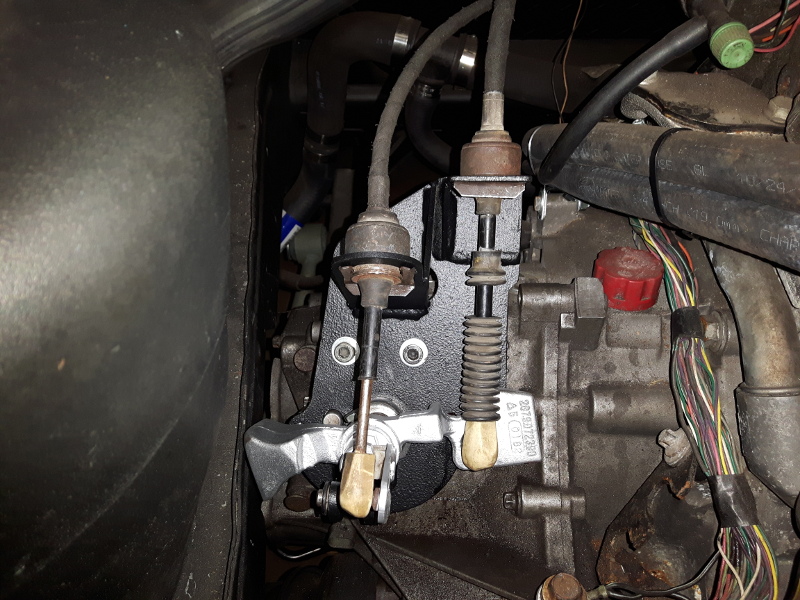
Since the car starts and runs, it's now time to make it shift. Here is the issue that I encountered. The shift arm is placed at an angle that doesn't work for me.
While others have had custom cables made, I chose a different approach. I wanted to utilize the stock 84 four speed shift and select cables. I removed the shift assembly from the F23.
Then disassembled.
Here is the stock shifter base.
I made a CAD drawing and cut it on the laser.
Then I cut off the boss for the select shift lever.
Here are the new and old pieces side-by-side.
As you can see, I also made two new arms for the select lever operation.
Since my base plate is steel, I can weld my arms wherever I feel they're best suited.
After some measuring, I filled the original dowel hole with weld. I then drilled a new hole in order to clock my shift arm into a better suited position.
Of course the F23 ball stud didn't fit the 84 shift cable.
Here, I removed the original F23 ball stud.
Drilled and tapped the hole to the pitch of the original 84 Muncie ball stud.
Here is the 84 ball stud on the F23 shift arm. Note: I removed some material from the weight for clearance.
While I did install a nut, it might have to be replaced with a thinner one for clearance.
New base is installed. I've used the original base, since it has the seal, and installed my new steel plate over top. There is a small gap that will be filled prior to final installation.
Followed by the re-clocked shift arm. While it looks close, the weight on the left actually clears the frame rail.
The shift cable has to fit in this vicinity.
That lead me into a way to mount the cables. Back to the drawing board, I ended up with this revised design.
I now have room to secure the shift and select cables.
Simple angle iron turned into the cable holders. Easy peasy.
It looks like this will work for the shift cable.
In the last photo, the cable was mounted too high. This is far better as it allows full range of motion from the shifter. Note: I'll mill slots into the angle iron thus allowing adjustability and fine tuning of both shift and select cables.
Nice work on your swap, that's a great find on the clutch hose, I assume it's a metric bubble flare on the other end...
Joe
Hey Joe.
Thanks for the compliment. I work on Porsche, BMW, Audi and VW vehicles on a daily basis. Finding the clutch hose wasn't too difficult. If I recall, it came off a fourth generation E46 chassis. I then seen an X3 that had a similar looking hose. To answer your question, yes, it required a bubble flare on the hard line.
Here's a few cars that I work on in any given day.
Today, I had one mission in mind; finish the cooling system. This started by installing the coolant tubes. Since my original clamps were rusted and I didn't trust using them, I made my own. For the middle, I used these. Simple 16 gauge made at home and painted.
I wrapped the coolant tubes with a piece of rubber hose followed by a little hockey tape to keep in together while I clamped it into place.
For the front, I merely used some "P" clamps and a little rubber to keep things snug. Perfect.
To keep hoses from slipping off, I had to replicate the beads that hold them in place. This was as easy as re-purposing an old set of Vicegrip pliers. I used a washer and welded it to the Vicegrips as shown.
I also created a relief in the opposing jaw. This gives the metal somewhere to go when forming the bead.
I sacrificed a spare 84 coolant tube. I've since installed the 88 ones on my car.
Here I cut off a piece to test with.
As you can see, the end result turned out rather well. I can now rest assured knowing my coolant hoses will not slip off.
Moving on, I used this exploded view and decided to copy the setup on my swap. Despite both cars using crossflow rads, the inlets and outlets were not identical. I solved this by crossing over the coolant lines and following the Ecotec design.
Here is the stock setup.
A few hoses and fittings.
After forming a bead on both ends, this tube was used as shown.
The left upper rad hose is just a 90° bearing the Topran part number: 102 721 586 The other end in a Northstar hose that I cut to fit. AC Delco part number: 26252X.
I needed a way to get coolant from the expansion tank at the back of the car to the front. Here, a simple VW Tee fitting was used.
The bottom crossover was kind of the same. I used a few sections from the old coolant tube and created this. I know, it looks like a plumbing fitting for a sink. It clears the swaybar and it fits well.
The lower rad hose is part number: 8754.
Now that the front was taken care of, I moved on to the rear of the car. My local Napa auto parts allowed me to look through their hose selection. I found hoses that looked like they would work with minimal modification. Here's what I ended up with.
The left side of the engine consisted of these two part numbers: 72174 and 8246.
They then created this monstrosity.
I took part of the 84 coolant tube and used it on the passenger's side. It clears the trailing arm well.
The right side looked like this by joining these two hoses together. Part numbers: 8942 and 8754.
This is the Cavalier expansion tank. It fits well in this unused space and is the highest point in the system. I now will fill the coolant and bleed the air from the system.
I also picked up a damaged Honda VFR800 for free. I'm not sure if I'll repair it or part it out.
[This message has been edited by Lunatic (edited 07-02-2017).]
While walking around the salvage yard, I spotted a fastback. Some parts have previously been removed. However, there were still some good parts left. I removed the steering wheel, the vapour canister, trunk seals and a spare shifter cable. Most of which will make their way onto my car.
After that excursion, I took the time to double check all my hoses and connections. Knowing all was tight, I filled the cooling system. For those with the 2.2 Ecotec, the thermostat goes into the housing first, followed by the plastic sleeve. Orientation as shown.
I was very pleased to finally have coolant in my car. I let it run for around a hour. In that time, I checked for fan operation, leaks, and weirdness. All is well, I called it a day. For the record, I used an Airlift device to fill the cooling system. It works perfect and is highly recommended.
Looking really good. If I wasnt so lazy I would copy some of the stuff you have done. I had time today to take a picture of my overflow bottle setup. The original hoses were printed on them where they went. So I just copied that .The large hose and one of the small hoses go back to the engine, the big one on the hose that has the tee on it and the small one to the fitting on the cyl head. The other hose I put to the puke tank fitting on the Fiero rad. Worked great at a hot track day on Thursday in Grand Bend. The hose under the tank cap is just open to the ground. I should put another catch can under that I suppose.
[This message has been edited by wftb (edited 07-22-2017).]
I needed to quiet down the exhaust as having just a catalytic converter with two resonators was way too loud. I ordered up a simple F-body muffler and some bits and pieces to make all this quieter.
While many of you have a full exhaust and and an uncut trunk, great. I just decided it would be best to remove the lower section of the trunk. The added room was welcome. Besides, I don't travel heavy and I won't miss the space. A Sawzall makes quick work of this.
Now, I chose to notch the rear cradle crossmember as I wanted the muffler canted forward. Here we go. Chop, cut, rebuild.
Here's a few pictures of the trunkectomy.
With all this room, I now had the ability to create a full exhaust system. Here is it taking shape.
It fits well and I like the look. I removed some Cadillac STS exhaust tips and added them to my car. They are the only chrome item on the car. I might paint them black after the car gets painted, we'll see.
Today, I spent some time working on electrical. My power mirror switch backing plate was very loose and not making good contact. I cut one from a parts car and installed. Both power mirrors now work. One more item checked off the "to do" list.
As you know, I've swapped in a 2.2 Ecotec into this car. Since I'm using the stock PCM and BCM, and not the Cavalier cluster, I needed to make the Equus aftermarket tachometer work with the Ecotec. Here's how I did it.
By looking at the 2003 Cavalier wiring schematic, a tachometer trigger signal is sent by the PCM through the serial data line and to the cluster where it's converted. Since I'm not using the Cavalier cluster, I had to go about this another way.
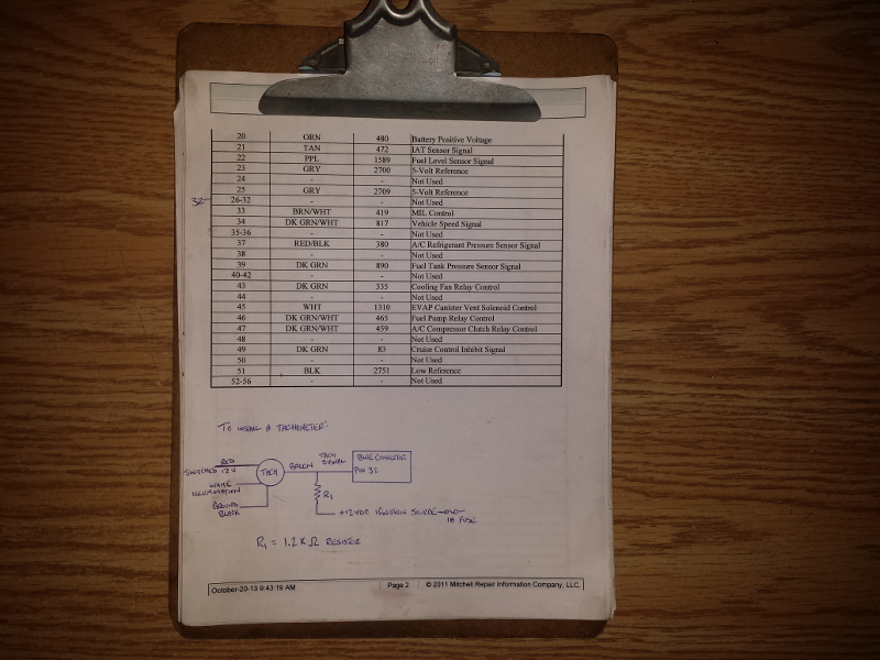
Looking at the PID value charts was useless as it merely states, "Not Used" on several pins.
By using an oscilloscope, each pin labeled "not used" was checked. Success was present when pin 32 on the blue connector showed an open collector output for a tachometer.
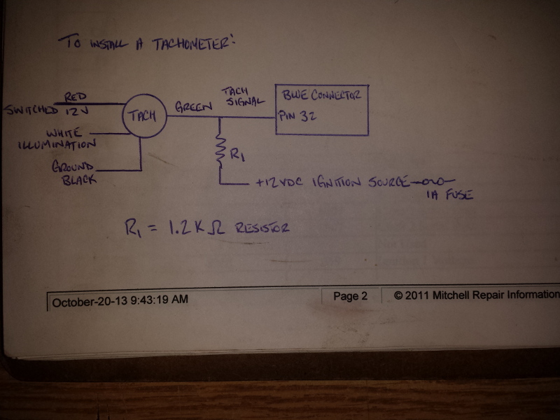
Since I had an aftermarket tach that doesn't have an internal "pull-up" resistor, I had to add one. Note: I didn't have a 1K ohm (1000) resistor handy but I had some 1.2K (1200) ohm resistors in my collection.
The pull-up resistor pulls the open (collector) output up to +12V. When the output transistor turns on, its collector terminal is connected to ground. Hence the output is a square wave from near-ground to near +12V.
Here's the schematic that made it all work, simple really. Note: My PCM part # is: 12576162
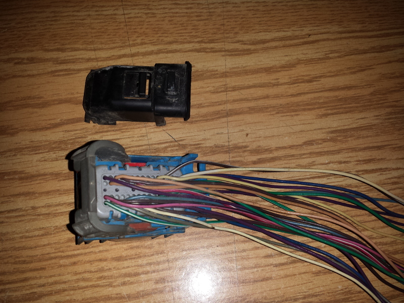
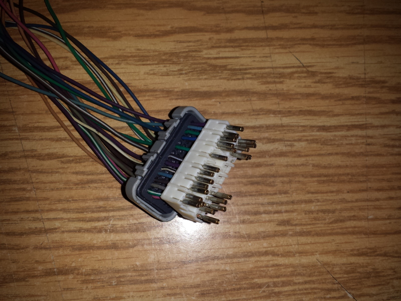
Since pin 32 was not used, there was no wire coming from the connector. I took another PCM harness pig tail and removed a white wire.
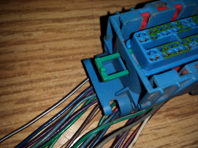
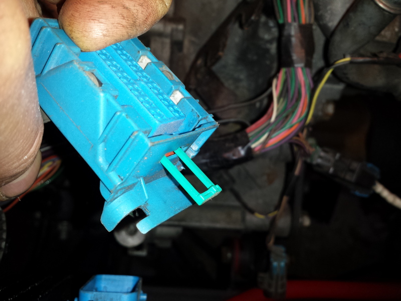
Remove the turquoise clip and unlock the connector.
This leads to exposed terminals and wires. I took a white wire just because.
On the car, I had to undo the clip and disassemble the connector.
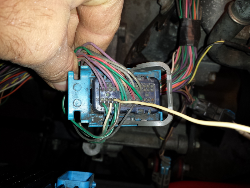
Since cavity 32 was unused, I had to drill a small hole in order to place the connector through. Here, you can clearly see the white wire protruding from cavity 32 on the blue connector.
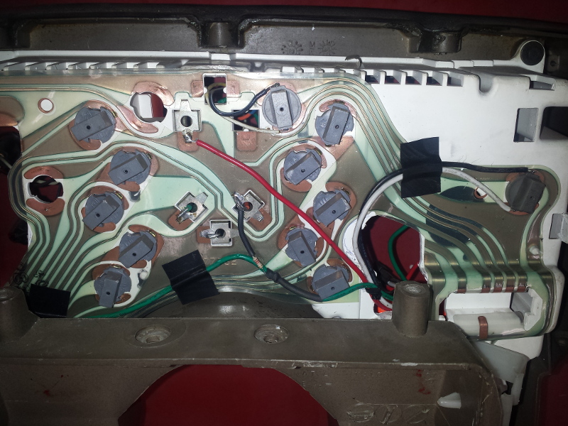
I extended this new white wire to the stock Fiero harness. I then chose to add the pull-up resistor in the back of the instrument cluster. In this location, I could tap into the two electrical points that I needed. -The green wire is the tach signal wire. -The resistor is then attached to the signal wire and the opposite end attaches to a keyed-on +12V.
A little video to show that it actually works.
[This message has been edited by Lunatic (edited 11-19-2017).]
Great work Shayne. I was looking at that GT in your picture at your scrapyard. Very surprised that no one has taken the fastback clip off of it and it looks like the whole body is in decent shape. Have a good one Steve
------------------ 86 GT built 2.2 ecotec turbo rear SLA suspension QA1 coilovers on tube arms
[This message has been edited by wftb (edited 02-04-2018).]
I wanted to use off-the-shelf parts for this modification. In this case, I'm referring to the stock '84 shift and select cables.
I'll let the pictures do the talking.
Here's my revised base plate.
To which, I've welded on other components. Here's the select cable bracket.
I also needed a select arm lever. Triangulation at its finest.
Some parts off the laser.
I had to utilize the pivot and ball studs from the original F23 assembly.
Not seen in the photo but the factory rubber isolator was removed and a bronze bushing was made on the lathe. This took up most of the slop in the shifter. Here's the final product all painted and ready to install.
Here, the stock '84 shift and select cables were siamesed for a little extra slack.
This slack will be welcome when it comes time to remove the oil filter cartridge assembly on the Ecotec.
Those are some nice cars. You must really like Fieros!
Perhaps it is BECAUSE he works on Brainless Money Wasters and WunderWagens that he doesn't want to actually own one.
quote
Originally posted by wftb:Great work Shayne. I was looking at that GT in your picture at your scrapyard. Very surprised that no one has taken the fastback clip off of it and it looks like the whole body is in decent shape. Have a good one Steve
It appears to me that Fiero parts are easy to get in southern Ontario. i had been looking for a rocker panel for like forever, and finally got one (free) while on a trip thru Toronto to Guelph. Perhaps the market is totally saturated with Fiero parts while the number of Fiero hotrodders is decreasing. Anyway, a great time to pick up parts for our cars. jon ------------------ I'm the original owner of a white ' 84 2M4 purchased Dec 10, 1983 from Pontiac. Always garaged, no rust, 4-wheel drifts are fun! 3800 SC swap to come!
[This message has been edited by longjonsilver (edited 08-09-2018).]
It looks like '88 coolant tubes will work with the earlier Fieros? From the way they bend towards the radiator, will a front mount battery box work?
Yes, the '88 coolant tubes work on the earlier cars. I can't comment on whether or not a front mounted battery box will work or not. I mounted my battery under the right front headlight assembly. Perhaps another member will chime in and answer your question.
Looking at your engine mount, i see that you are using a single mount. My duke motor also has a single mount, and it depends on the dogbone to hold it from rattling fore and aft. Because of this it has worn our numerous dogbones, including the poly one that i have in there now. i would like to go with a double engine mount like some use on the 3800 swap. Could a double engine mount be used on the Ecotec block? thanks jon
------------------ Astronomy says we will find a coded signal from outer space. Then we'll KNOW that life exists there, for coded signals aren't by chance.
Biology says there are coded genetic signals in every cell, but we KNOW that no intelligence created life.
I'm the original owner of a white ' 84 2M4 purchased Dec 10, 1983 from Pontiac. Always garaged, no rust, 4-wheel drifts are fun!
Looking at your engine mount, i see that you are using a single mount. My duke motor also has a single mount, and it depends on the dogbone to hold it from rattling fore and aft. Because of this it has worn our numerous dogbones, including the poly one that i have in there now. i would like to go with a double engine mount like some use on the 3800 swap. Could a double engine mount be used on the Ecotec block? thanks jon
I'm using one lower mount, under the oil pan, and also a diagonal brace that triangulates from the cylinder head to the cradle. This along with the two poly transaxle mounts, keeps everything secure. I'd have to take a look at the spare Ecotec that I have sitting here in order to determine if there's a decent spot to run two dog bone mounts securely. There's always the option of using four mounts, two on the transaxle and two on the engine in a colinear placement. This will most certainly not require the use of any dog bones. If I pull the Ecotec out and go with something bigger, think V8, then I'll go that route.
i'm going to be heading out to the junkyard tomorrow to pull a booster off a 97 GMC Sonoma. i like the way that you swapped out the rod and the bracket to make a frankenbooster. i think that i might try the same. Your writeup is really well done, and is inspiring me to make this change. i also might put my battery in under the passenger headlight. All of this once i take the car off the road, because i don't want to be rushed, and i don't want to limit my driving in the next 30 days- i take it off the road the end of October. i pulled 1/2 a headlight harness today from an 87 and 1/2 from an 86, because someone cut the 87 harness that i need to install my Gen 2 headlight motors. i get to join the two together. My passenger motor in my 84 messed up and now i raise and lower it by hand. Don't wanna do that next year. So i get to do the booster, the battery, the headlight harness, and i just put in a 3 core radiator, gotta pull it to install the headlight harness. Question: can you tell just by looking if the guts of the junkyard booster are good?
jon
------------------ Astronomy says we will find a coded signal from outer space. Then we'll KNOW that life exists there, for coded signals aren't by chance.
Biology says there are coded genetic signals in every cell, but we KNOW that no intelligence created life.
I'm the original owner of a white ' 84 2M4 purchased Dec 10, 1983 from Pontiac. Always garaged, no rust, 4-wheel drifts are fun!
i'm going to be heading out to the junkyard tomorrow to pull a booster off a 97 GMC Sonoma. i like the way that you swapped out the rod and the bracket to make a frankenbooster. i think that i might try the same. Your writeup is really well done, and is inspiring me to make this change. i also might put my battery in under the passenger headlight. All of this once i take the car off the road, because i don't want to be rushed, and i don't want to limit my driving in the next 30 days- i take it off the road the end of October. i pulled 1/2 a headlight harness today from an 87 and 1/2 from an 86, because someone cut the 87 harness that i need to install my Gen 2 headlight motors. i get to join the two together. My passenger motor in my 84 messed up and now i raise and lower it by hand. Don't wanna do that next year. So i get to do the booster, the battery, the headlight harness, and i just put in a 3 core radiator, gotta pull it to install the headlight harness. Question: can you tell just by looking if the guts of the junkyard booster are good?
jon
Jon,
You're making some good choices on you mods for your Fiero. The gen two headlight motors are nice and I too might go that route. There are still Fieros in some of the salvage yards that I frequent.
As for finding a decent vacuum booster, look for the nicest, shiniest one that the salvage yard has. Heck, if it's still in the vehicle, and the engine is intact, you might even hear the vacuum leak out once you remove the vacuum line. That means it holds vacuum and isn't leaking. That's always a good sign.
I used what I had here. In essence, you could also purchase a brand new one and modify it. I don't think they're too expensive. Good luck with your mods over the winter.
i found a GMC Sonoma 1997 with a good looking power booster. i noticed that in all the S10s and Blazers that i looked at, many had the master cylinders missing, but the power boosters were ALL there. That tells me that power boosters don't fail often, and if i get a bad one, i will need one for a core anyway, and the core charge is higher than the junkyard price. i reason like this: a different (S10) wheel caliper weighs more and that is unsprung weight. There is no reason fro street driving to have vented rotors, because i don't use my brakes that much and don't drive on hills a lot. So the only thing that will give me better brakes is more pressure at the wheel calipers, which means a bigger booster. i went down this road and then came across your frankenbooster mod, well before i learned about the 100$ brake thread. It rang a bell of truth to me - and i want better brakes.
i have been soldering my frankenharness together, something like 25 solder joints in the main harness, and someone cut off all the marker lights and turn signals so i need to pull some electrical fittings so i don't have to cut into my 84 harness if i don't have too. That makes another 10 solder joints, at least my frankenharness will have two horn wires.
i see on Kijiji that there are lots of ecotecs for sale cheap. One guy in alberta wants only 200 for the complete thing - wiring harness, computer, clutch, transaxel, alternator etc. i question the condition tho. Still think i will hold out for a 2.4 that will hold up better to a supercharger. Still it is very tempting as my duke is burning a lot of oil. Like a quart every 1000kilometers. Thats a lot! Runs pretty good tho, so no rush. Maybe not this winter but next winter possibly. i also have to replace my dew wipes and sew another seat for the drivers side, replace the condensers in my tach board, and in my delay wiper board. While the door skin is off i need to repair my passenger side door handle, and fight rattles. Possibly the drivers side door pins too. Radio cassette needs repair. That'll keep me busy this winter.
jon
------------------ Astronomy says we will find a coded signal from outer space. Then we'll KNOW that life exists there, for coded signals aren't by chance.
Biology says there are coded genetic signals in every cell, but we KNOW that no intelligence created life.
I'm the original owner of a white ' 84 2M4 purchased Dec 10, 1983 from Pontiac. Always garaged, no rust, 4-wheel drifts are fun!
Whenever I am looking for a new to me engine, I go to the OARA (ontario automobile recyclers association) website and do a search. When I got the eco that is in my car now, there were about 300 available at various yards around Ontario. I used the same search engine to pick up like new factory alloy wheels for my Focus and my youngest son's Honda Fit.
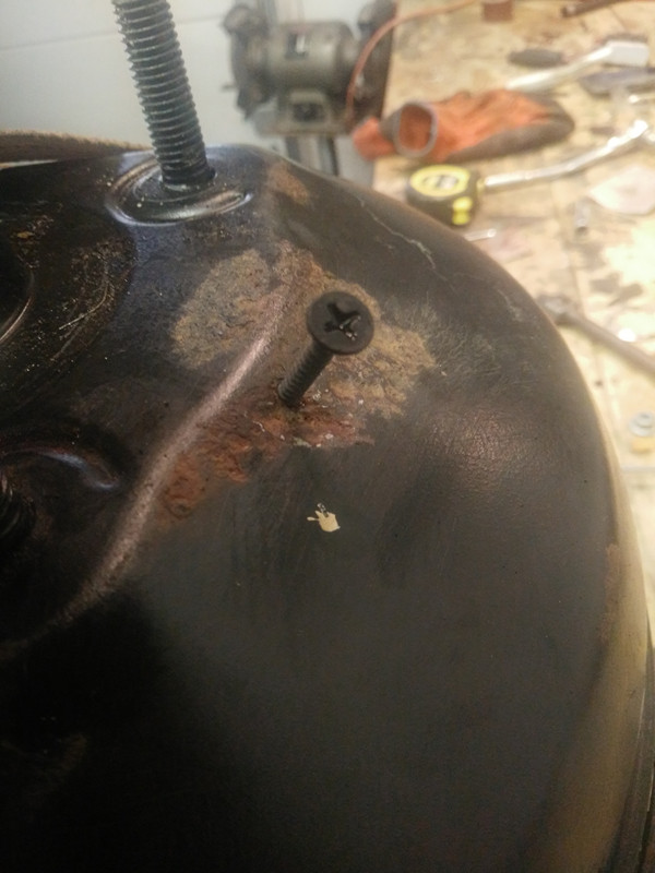
i am attempting to duplicate your frankenbooster. i went to the scrap yard and pulled a booster off a 95 GMC Sonoma 4cyl, 2wheel drive, rear drum brake model. i have found when attempting the conversion that there is a hole in the bottom due to a rust spot, that was not visible until i began cleaning it. Will this hole negate my vacuum?
Also i have had trouble pulling the snap ring off the Fiero plunger, but i took off the washer thingy off the back and removed the whole plastic cylinder with the plunger in it. i think that it just might fit into the Sonoma booster. How in the world did you get that snap ring off down deep in the hole of the cylinder?
Do you think that my idea will work? thanks jon
edit: since the booster is in vacuum (it is in vacuum no?) couldn't i repair the hole by cleaning well with a wire brush and sandpaper and solvent, and then use JB weld? The vacuum will be sucking in the repair, not pushing it out. ;-)
------------------ Astronomy says we will find a coded signal from outer space. Then we'll KNOW that life exists there, for coded signals aren't by chance.
Biology says there are coded genetic signals in every cell, but we KNOW that no intelligence created life.
I'm the original owner of a white ' 84 2M4 purchased Dec 10, 1983 from Pontiac. Always garaged, no rust, 4-wheel drifts are fun!
[This message has been edited by longjonsilver (edited 10-11-2018).]