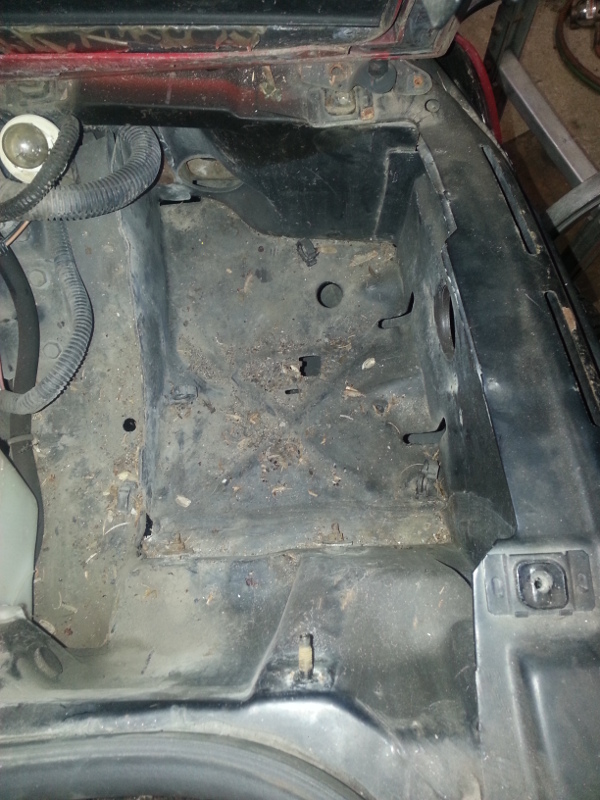
Here's the area that the fuel filler tube goes through. As you can clearly see, we have some missing metal. Lets take care of that.
Open area that needs to be filled.
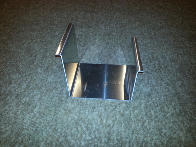
Here's the piece after a hammer and dolly session and a trip through the sand blaster. I'll weld in a patch over the small hole next time.
Looking better and getting there.
Battery tray was damaged and here's what I could salvage. I'll add more metal after I make a nice template.
While I was in the back of the car, I removed all traces of the original dog bone mount bracket.
I also added 1/4" rivets to pin the shock towers to the frame rail.
Sealed the holes in the firewall from the removal of the deck lid hinges.
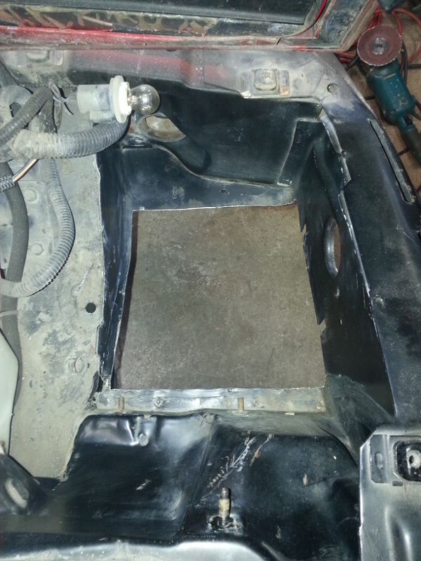
I made a template to contour the left side of the firewall where the filler tube meets.
Transfer the line to the checker plate panel.
Cut on the transferred line.
If your measurements and template were good, then adhere the checker plate in place. Voila.
My friend is a member in a local car club in the area. I decided to fire up Solidworks and make some custom vanity plates for the guy's there. I made them out of 16 gauge steel and everyone loved them.
[This message has been edited by Lunatic (edited 12-19-2014).]
I didn't mind the look when I did the same thing with my SBC/Getrag Fiero, but I found that over time the aluminum caught fibers from my wash sponge/drying towels, would scuff easily, and lose its mirror finish. So since that first time, I haven't used it again, but instead use smooth sheet metal now.
Thank you for viewing along. It's my pleasure to share with such an awesome community.
quote
Originally posted by jmbishop: I really dislike diamond plate. Not saying you shouldn't use it if you like it, I just never found it appealing.
quote
Originally posted by ericjon262: I have to agree here, it's just too flashy, but it is your car.
I'm in agreement with you guys. This is not a high-end build nor am I building a show car with "bling". Like many of you, I simply want a nice, clean engine bay and I thought the checker plate would easily cover up the ugly underneath. It will get coated/painted as to not stand out quite as much.
quote
Originally posted by fieroguru: I didn't mind the look when I did the same thing with my SBC/Getrag Fiero, but I found that over time the aluminum caught fibers from my wash sponge/drying towels, would scuff easily, and lose its mirror finish. So since that first time, I haven't used it again, but instead use smooth sheet metal now.
I too liked the look of your blue car. You are correct in saying the mirror finish does scuff quite easily and loses shine over time. I once had a checker plate tool box that was coated with an anti-slip, flat black texture finish. I really liked that and that's what I'd like to do to the engine bay. It looks great and hides small imperfections. In the end, I'd like the Ecotec to look it's best and be surrounded by a clean engine bay.
While scouring the local classifieds, I found two Ecotec engines close to me. Both are the same L61 family. One being 03, the other 05. I was looking for a good core engine for future mods but now I have two. One had internal mechanical damage, from what the previous owner said. It sure looks like it as the valve cover is off and the cam followers are damaged. Probably a timing chain let go. I'll investigate later on. The other engine ran in the fall apparently. Again, I'll dissect them both and see what I've got. As I said, I only want a good core. Besides, getting these saved me the hassle of going to the salvage yard and pulling my own. Don't mind the snow, they were laid on their side for the ride home.
[This message has been edited by Lunatic (edited 12-21-2014).]
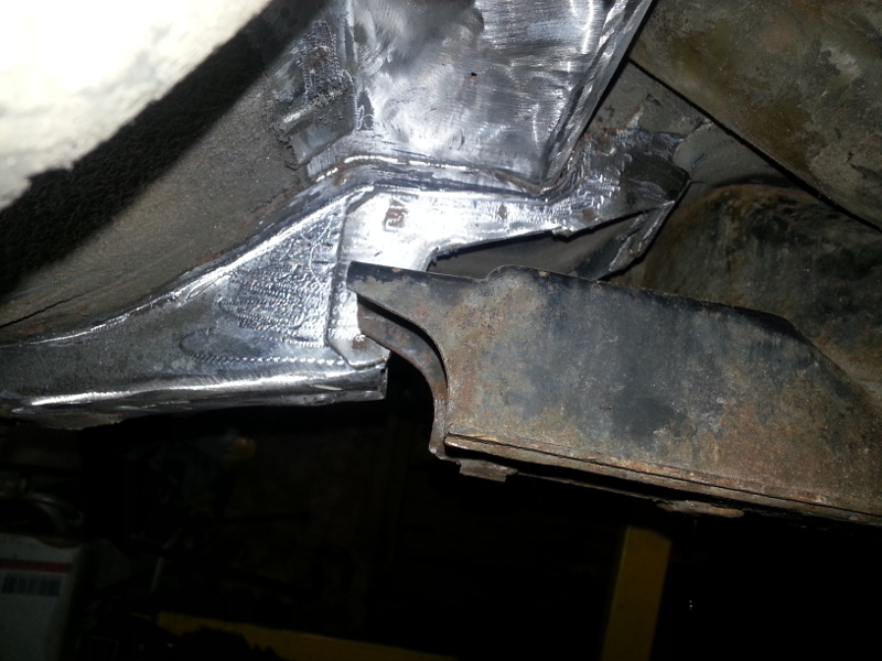
There are a few more area's that must be addressed. After removing the factory bracketry, you can clearly see the back two mounting locations are floating in the air.
The bracket that's already been removed from here already has the bolt hole in the right location fore/aft and left/right... it's just at the wrong height. It's easier to section the stock bracket to raise the mounting pad to the right location then weld it back together. That way you also retain the stock captured nut and don't have to deal with loose hardware.
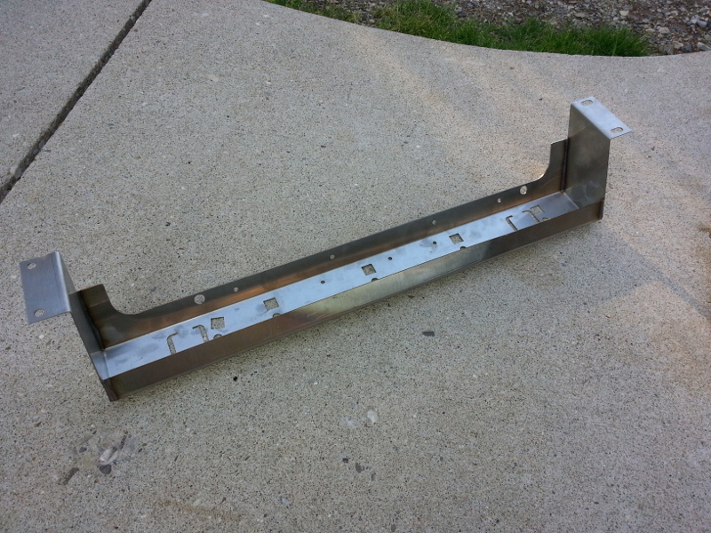
In hopes of finding a "nice" rad saddle, and not finding one, I decided to just make one. I whipped this up, cut on the laser and formed on the brake. Just for something to do of course. Lol. Ooh, aah, stainless too! No crusty crap here any more.
That's a really swift product. I think you could sell a few of those... especially if they bolt in and work with stock radiator and mounts, while also allowing room for a specific larger aftermarket radiator. Obviously, you can't design for all aftermarket radiators...
Thanks for the reply. Indeed, I could replicate and modify the parts that you've shown and come up with an equally nice component for the Fiero. I've also posted another option. The below items can be bought fairly inexpensively and they provide adjustability which is nice as it can compensate for different offset wheels and such. I like both options and I'll keep you informed as to what route I go with.
Did you make those solid rod ends yourself? I've been looking for similar parts to meet some specific dimensions. My personal opinion is nothing but spherical bearings for the '88 lateral links.
Also, are you going to raise the inner pivots relative to stock?
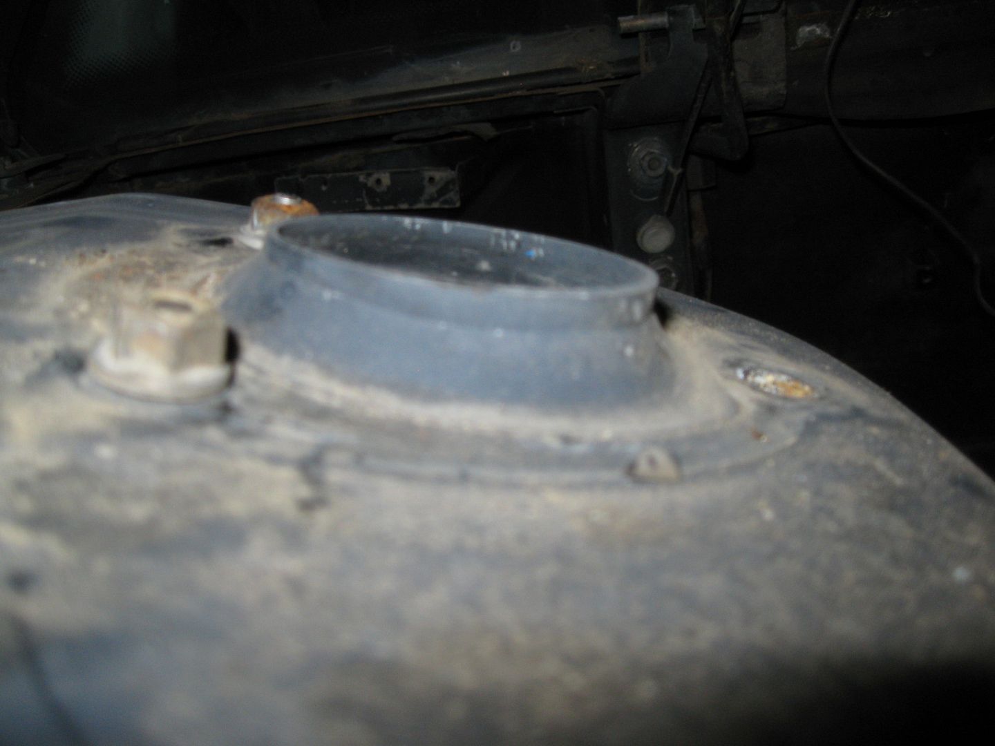
Originally posted by Will: Are those the '84-'87 strut towers or the '88 ones?
Those are the 84-87 strut towers. You can see where the three separate oval wahsers were, plus the geometry of the center hole isn't the same as the 88's. Here is an 88:
There are a few more area's that must be addressed. After removing the factory bracketry, you can clearly see the back two mounting locations are floating in the air.
The bracket that's already been removed from here already has the bolt hole in the right location fore/aft and left/right... it's just at the wrong height. It's easier to section the stock bracket to raise the mounting pad to the right location then weld it back together. That way you also retain the stock captured nut and don't have to deal with loose hardware.
I knew it was close but I never took the time to see how close. There you go folks, great information for all those that are looking to do the 88 crossmember swap. Thanks Will for pointing out this alternative.
[This message has been edited by Lunatic (edited 12-23-2014).]
In hopes of finding a "nice" rad saddle, and not finding one, I decided to just make one. I whipped this up, cut on the laser and formed on the brake. Just for something to do of course. Lol. Ooh, aah, stainless too! No crusty crap here any more.
That's a really swift product. I think you could sell a few of those... especially if they bolt in and work with stock radiator and mounts, while also allowing room for a specific larger aftermarket radiator. Obviously, you can't design for all aftermarket radiators...
I've had a several PM's about this rad saddle that I made. So it appears as though there's interest in this product. It was fairly close to the original that I used to measure from with a few minor variations. With having said that, it fits the stock rad. I did make mine as wide as possible to accommodate a larger rad if needed. I was thinking of making one more and offering it to a member on here that could install, evaluate and see how well it works. Once I receive reply from said member, I'd make any changes to the final product and then offer them in the mall.
Originally posted by Lunatic: Thanks for the reply. Indeed, I could replicate and modify the parts that you've shown and come up with an equally nice component for the Fiero. I've also posted another option. The below items can be bought fairly inexpensively and they provide adjustability which is nice as it can compensate for different offset wheels and such. I like both options and I'll keep you informed as to what route I go with.
Did you make those solid rod ends yourself? I've been looking for similar parts to meet some specific dimensions. My personal opinion is nothing but spherical bearings for the '88 lateral links.
Also, are you going to raise the inner pivots relative to stock?
When I started my build, I only had 84 parts to use. Soon after, I found the 88 specific uprights locally. I then had to find stock lateral links and radius rods since I never had them to measure from. A guy I know is also building a Fiero. These are the links from his car. They're made by Bicknell Racing in St. Catherines Ontario, Canada and I'm not sure if he bought the ends like that or made them.
Their part numbers: 13170 for the long bar, 13090 for the rear lateral bar, 13080 for the front lateral bar.
I was going to get a set but since I already bought stock 88 pieces, I'll probably just use them. I also have spherical joints, swage tubes and the special seals. I think I'll save them for now.
I did not raise the inner pivots and they are still in the stock location. I now see the benefit of raising the mounting points and I will probably do this as my cradle hasn't yet been powder coated.
[This message has been edited by Lunatic (edited 12-23-2014).]
Originally posted by Lunatic: A few 1/4" holes rosette welded and the right side is coming along.
Are those the '84-'87 strut towers or the '88 ones?
Yes, these are the 84-87 strut towers. I did have the back half of an 88 but it was hit in the side. I couldn't get it to line up with any of my measurements as it wasn't square any more. I went back to the 84-87 style. I'll be making coil overs for the rear and move the top of the strut to where the 88's are. I'll also make a nice cover for it so it looks factory.
Note: To those swapping in an 88 cradle into an 84-87 chassis. Here are the proper 88 strut mounting point locations.
When looking "DOWN" from the top of the 84-87 engine bay, and standing behind the rear of the car facing forward, the new 88 strut shaft centreline location will be:
INWARD (47.625mm) or 1.875" (1 7/8") FORWARD (30.1625mm) or 1.1875" (1 3/16")
These measurements are "per strut". You'll have to move both struts!
I work out of a small garage and space is sometimes at a premium. Now with two additional Ecotec engines on the floor, I need to make a little room. As you know, I have one complete, running L61 Ecotec and two mystery core engines. I want to install one as a stock runner and enjoy it for a while as-is. The next one, I'd like to have a little more power and I'd like to freshen it up.
Mystery engine "B". Notice the loose timing chain?
Rusted cylinder walls and water jackets damaged in three places!
When a timing chain slips on the interference Ecotec, bad things happen!
Holes in all four pistons from valve stem parts dancing around the combustion chamber.
Mystery engine "A". This one turned over a little tight but it's way better shape internally than the other one
Ringland on cylinder one was damaged/missing.
All 16 valves look okay.
In all, I have one good core and I can salvage a few parts (intake, sensors, oil pan, etc) from the "parts engine".
Note: Early Ecotec engines had a poorly designed cam chain tensioner. Do yourself a favour and get the "upgraded" version. They're cheap and will prevent damage like shown above.
[This message has been edited by Lunatic (edited 12-26-2014).]
Funny thing about the tensioner , it took 3 designs to get it right .I get mine from crate engine depot , they do not have any of the old ones in stock .With a local dealer , you never know if you might end up with the older design .
When I started my build, I only had 84 parts to use. Soon after, I found the 88 specific uprights locally. I then had to find stock lateral links and radius rods since I never had them to measure from. A guy I know is also building a Fiero. These are the links from his car. They're made by Bicknell Racing in St. Catherines Ontario, Canada and I'm not sure if he bought the ends like that or made them.
Their part numbers: 13170 for the long bar, 13090 for the rear lateral bar, 13080 for the front lateral bar.
I was going to get a set but since I already bought stock 88 pieces, I'll probably just use them. I also have spherical joints, swage tubes and the special seals. I think I'll save them for now.
I did not raise the inner pivots and they are still in the stock location. I now see the benefit of raising the mounting points and I will probably do this as my cradle hasn't yet been powder coated.
I'm still plugging away at this project despite the cold weather and lack of heat in the garage. However, I've made a little progress. I'm looking to smooth out the engine bay a little. Nothing major, just remove any offending areas and sharp edges. (Body filler will be applied to smooth things out further.)
A few cardboard templates and then a transfer to light gauge sheet metal is in order.
In the preparation of reinstalling the rear window, one first has to remove the old urethane sealer. This is easily accomplished by using the right tools. I removed as much of the old urethane using a sharp utility knife. Then the remainder was easily removed using a Walter wire wheel. This makes the job pleasant and the results speak for themselves. Yes, I'll apply the proper primer before the window goes back in. But that's for another day.
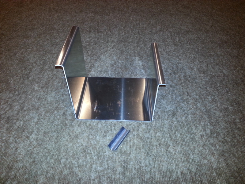
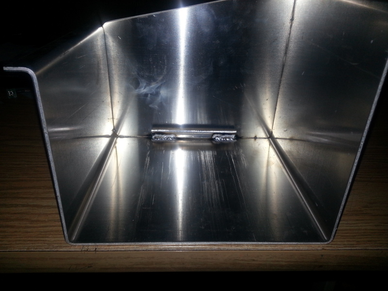
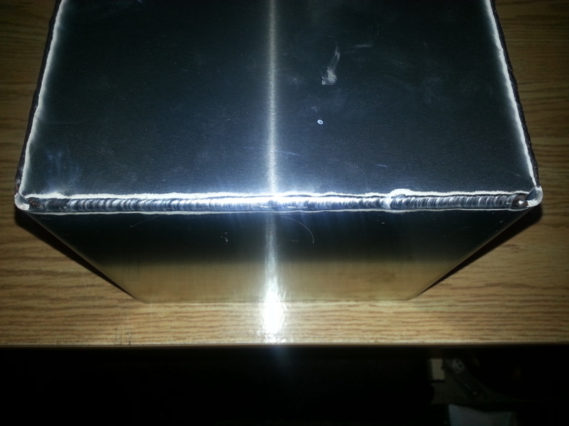
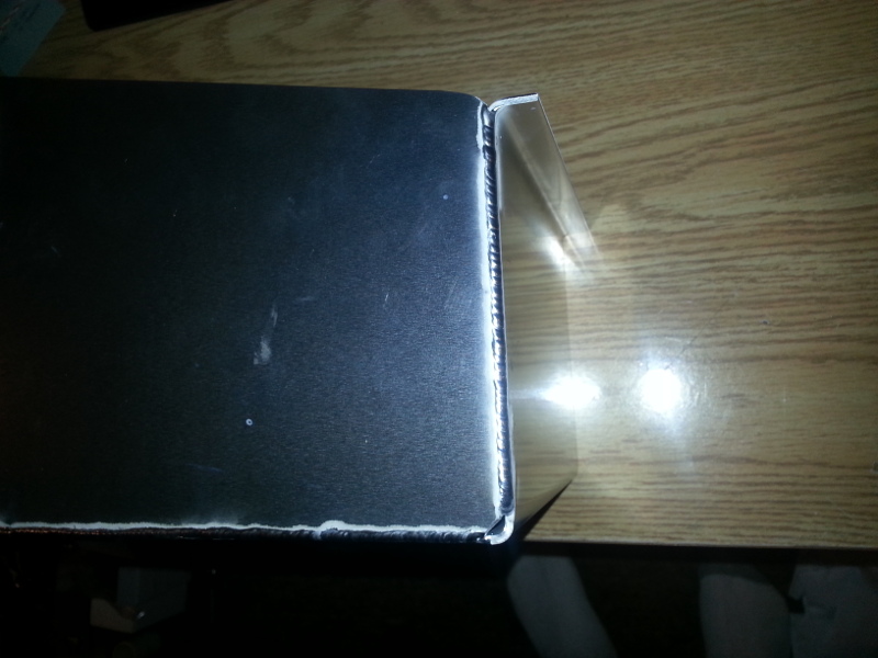
Since I mentioned it was cold earlier, I decided to make a model of the fuel tank. (In the warmth of my house!) Yes, I'll be building an all aluminum fuel tank for this car. It's a wee bit bigger than stock 87 tank that I used to measure from.
Note: I will be adding baffles to the inside. They're just not shown here.
I used thick cardboard to make the fuel tank body.
I installed this cardboard model into position and since it fits well, I can now commit to cutting on the laser using 5052 1/8" aluminum. I'll make a video of the laser in action once I get to that point. That's all for now.
[This message has been edited by Lunatic (edited 01-18-2015).]
having made a cardboard tank(not fuel though) for mock up purposes myself, I strongly recommend that you test fit that tank every step of the way. I had a tank built for my turbo 3500 swap and it almost didn't fit. cardboard flexes in ways aluminum doesn't.
Okay, I'll admit, I've been a little slack. February indeed was way too cold to be out in the garage. But now, I have some motivation again.
I cleaned, flushed, inspected and pressure tested the stock dual-core radiator and it passes my inspection. I also picked up a new rad cap to accent the now clean and ready-to-install rad.
After inspecting my old clutch master, I decided not to reuse it. Instead, thanks to Netcam, I just bought his new one. (I think it's a unit from Rodney Dickman).
I wanted a complete polyurethane bushing kit to replace my worn out OEM bushings. This was easily accomplished by placing an order through the Fiero store. Very quick shipping too, three days.
That leaves the ball-joints. Well, the 88 upper is made of unobtanium and cannot be found locally (in Canada). Instead of finding something dimensionally close, and making it fit, I chose to place an order with Rodney Dickman.
New upper and lower ball-joints, steering rack bushing, new rear upright through bolts and tie rod end boots. Again, package arrived fairly quickly at my door in only four days.
Since I'm refreshing all the old, worn out parts, it only makes sense to get all new grade 10.9 hardware for the suspension.
Even though I have some new parts and I'm excited to install them, I still need to maintain the rest of the fleet for the upcoming season. I need to move to a planet that has 36 hours in a day!
PS-Upon opening a shoe box full of oddities, I found something....
[This message has been edited by Lunatic (edited 03-15-2015).]
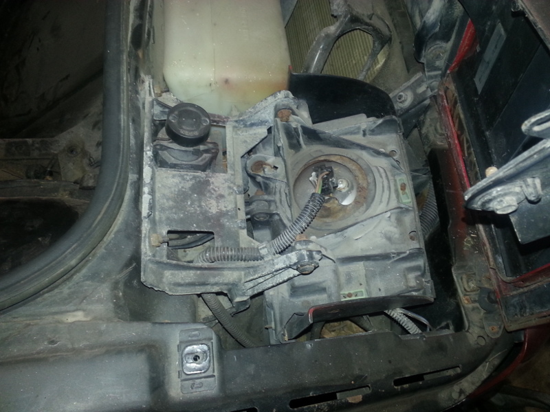
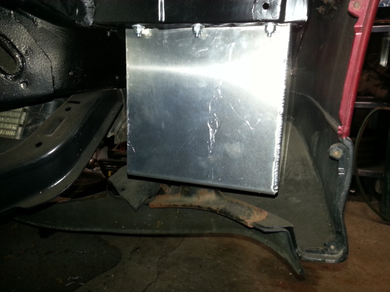
I'm aiming for a clean engine bay. With having said that, the battery will be relocated to a better area. What better way than to move it under the passenger side head lamp. This consists of making a battery tray, removing the area under the headlight and bolting in the tray. I used 1/8" aluminum for this project and yes, the stock battery hold down bracket will be reused, it's not shown in the photos though.
Note: I'm using the GT fascia. (This battery box will be hidden by this fascia). Non Aero cars might not be able to get away with this mod as the battery may interfere with the plastic.
Passenger side head lamp assembly.
After removal.
Cut the sheet metal and you're left with a hole.
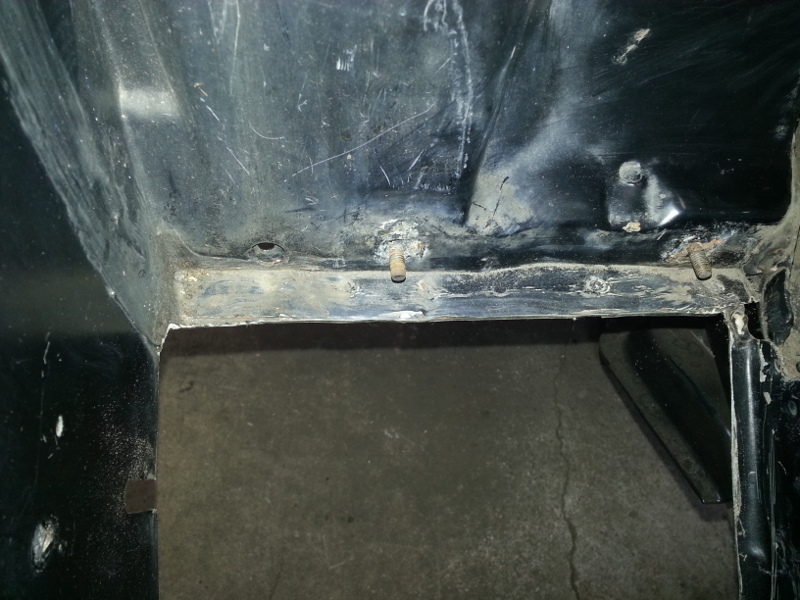
Trim these two studs a little as they interfere with the battery box flange.
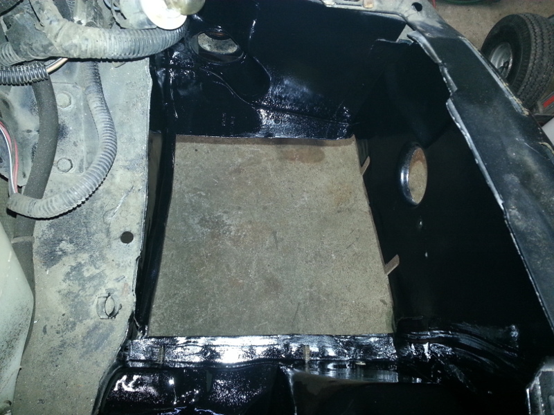
Now is a good time to paint the area since it's exposed.
Great stuff. I'm curious how low your battery sits, and if you will still have room on top for the headlights.
I thought I put mine pretty low and I had no intent to put pop-up lights back in, but since my project took a different turn, I'm looking to put the pop-ups back in and fear they won't fit now.
How do you plan on servicing the battery if needed?
Bob
Thanks for commenting Bob.
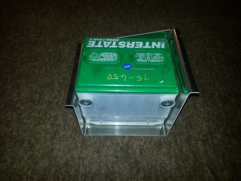
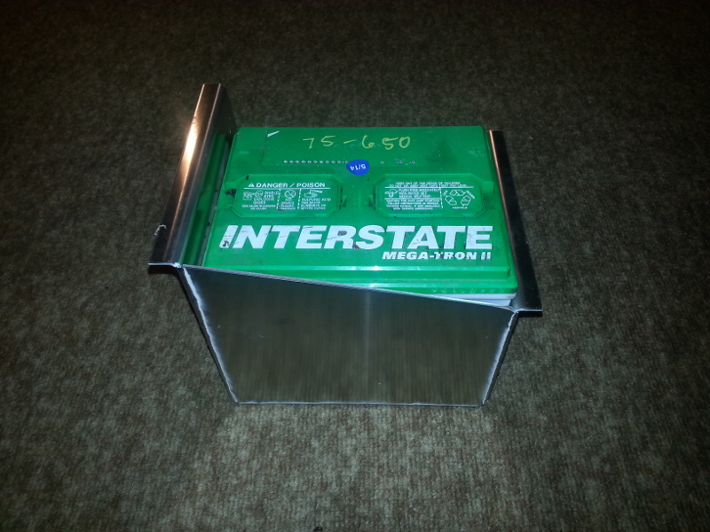
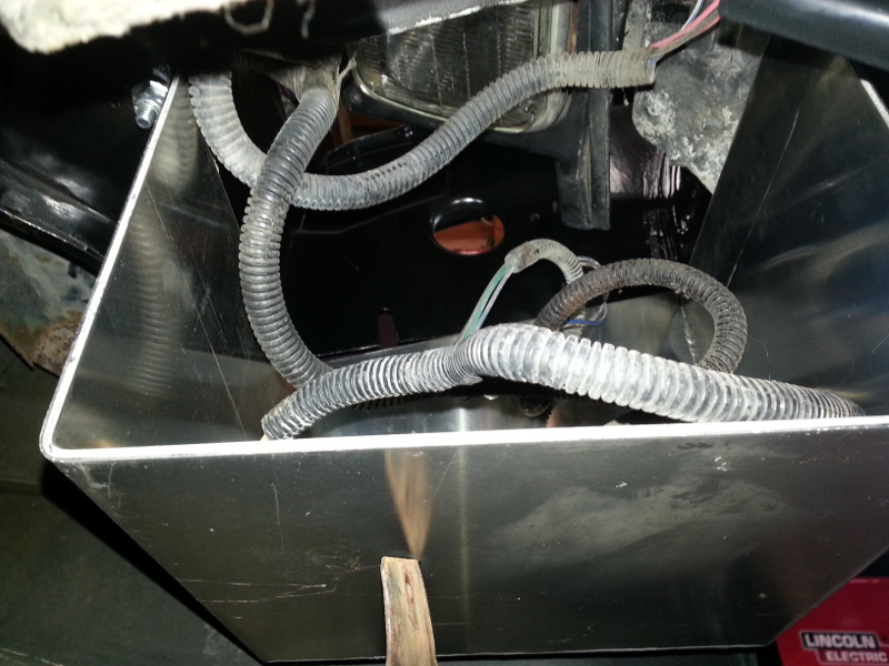
From the floor of the battery tray to the lowest part of the headlight assembly (in its lowest, parked position) is 8 3/4". My battery is 7 3/8" in height. Therefore I have 1 3/8" of clearance. As for servicing the battery, I'll look into a quality unit that needs little maintenance. Perhaps a sealed unit from Optima. Either way, it's only a few minute job to remove the headlamp assembly if needed.
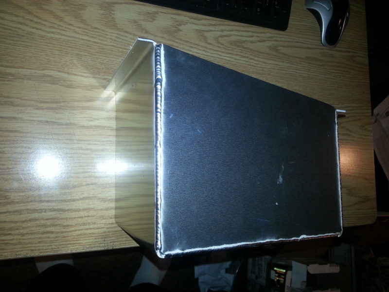
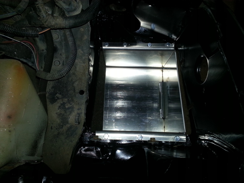
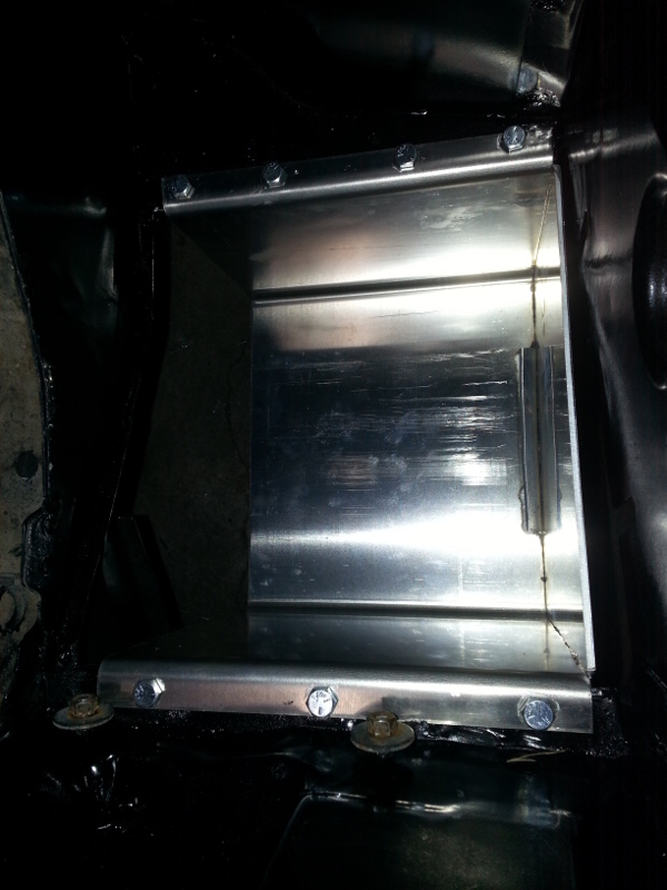
Here's two more pictures. Despite not showing the battery in position, here you can see the clearance.
If I remove the curved steel from the bottom of the fascia, I can bolt that area to the battery box. (That should be a good indication of how low my battery box sits).
[This message has been edited by Lunatic (edited 03-24-2015).]
Although April was very busy for me, I did manage to get some things done on the car. This time, the front of the car got a little attention.
Since I had used parts, they must be disassembled, cleaned and inspected before going into service. 88 rack disassembled, cleaned, inspected and painted.
Clean parts and new brass bushing.
Stake the inner tie rod. (You can also see the generous amount of grease).
Brass bushing correctly installed, more grease and yes, I painted the rack while it was apart.
The brass bushing, when installed correctly, sticks out 8 mm as seen. I used 3 rivets 120° apart to secure the bushing.
Index marks for setting the pinion tension.
Bellows and rubber mounts installed on the now clean rack.
Painted the rack hold down brackets.
I removed the spare tire tub for better access.
See, more room.
88 specific steering shaft.
This flexible cover from the 84 doesn't fit the 88 intermediate shaft because of the rag joint. I'll have to look into finding the correct one. Anybody have one to sell?
Rack installed. The original nuts on the backside of the crossmember were missing. I chose 3/8"-16 x 1" zinc plated with Nylock nuts. Note: You can get a wrench on the back side to hold the bolts from turning.
Since the factory shop manual, nor Rodney's instructions mention the torque of nut #7, I'm going with the 28-40 ft-lb scale since it's an M10x1.5 nut. Exploded view from FSM.
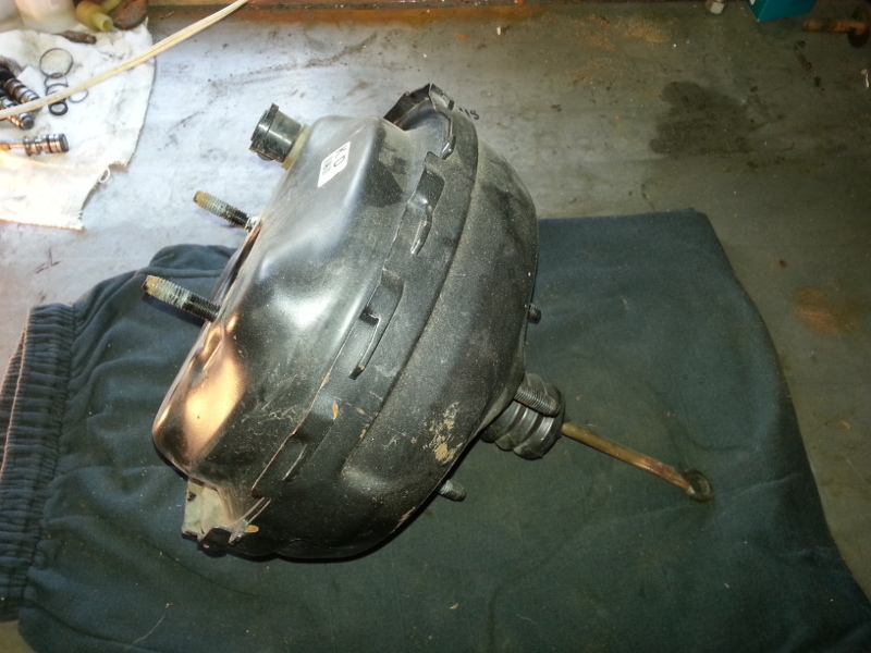
For those of you that are interested in the installation of a larger brake booster on your Fiero, this is for you. It's not that difficult to do, really. Follow along if you will.
Note: Some use the 96 S10 booster for this mod. I used a 1995 Suburban booster because I had it. It's an 11" dual diaphragm design. It also has studs that make in easy to bolt the Fiero booster bracket to.
Remove the old booster from the car. You can actually move the brake master out of the way, leaving the brake lines intact. You'll have to remove the little screw that holds the proportioning valve in place. Once this is done, unhook the booster pushrod from the brake pedal, remove the four bolts from the booster, and place it on the bench. We need some parts from the stock Fiero booster.
Note the pushrod length. This unit is longer and will be reused in the larger booster. Yes, it's a direct swap.
This is the bajonet fitting. You'll see there are a few places that are staked. These need to be unstaked. Using a screw driver makes this easy.
Here is what it looks like unstaked. Do this on all the area's needing it.
Place the booster in a vice as shown. (Use aluminum angle on the jaws of the vice to protect the threads). We're going to rotate the housing around 1/16th of a turn. It does have a spring in there and it will fly apart. Prepare yourself and get a helper to hold down the top of the booster while you rotate.
Disassembled, this is how it looks.
In this photo, you'll need to remove this lock clip.
Exploded view.
Look way down and you'll see a circlip. Carefully remove this.
Pull out the pushrod like shown.
This is what you need.
Now, cut the bracket off the Fiero booster. We'll reuse this on the new booster.
This is the bigger 11" booster.
Like you did with the Fiero booster, take the new one apart the same way. You can see the different length pushrods between the two. The Fiero pushrod is the longer of the two. This is what we'll be using in the bigger booster.
Circlip, pushrod and seal.
Insert pushrod into bore of new booster.
Circlip sitting on top, ready to be installed.
Circlip properly seated.
Retainer, spring and seal goes on.
At the top, you can seal the simple lock ring.
Turn the booster around and install the plastic guide.
Next the spring retainer goes on.
Now the spring.
The front of the booster now gets installed. Compress the spring, and rotate slightly to lock in position.
The studs are too long in my opinion. Cut them to aid in the installation.
The stock Fiero plastic sleeve, on the right, is reused.
Use new nuts with the Nylock insert.
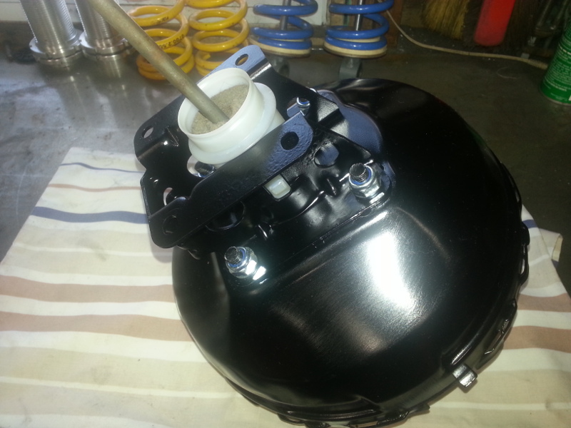
Bolt the Fiero bracket that you cut off earlier. I painted mine to match.
You will have to clearance for the bigger booster. Several judicious blows of a hammer in the offending area take care of this.
Add some paint.
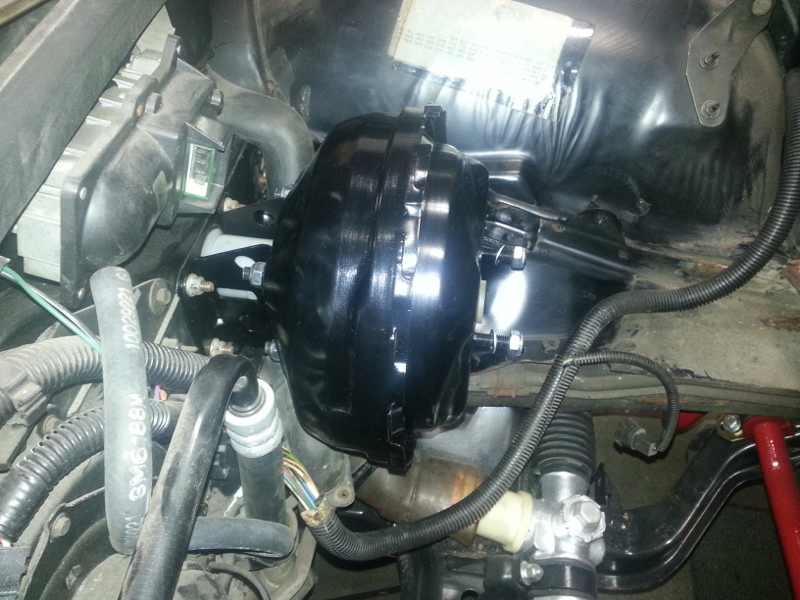
Install the newly modified 11" booster.
Reattach the master cylinder and enjoy! See, easy.
[This message has been edited by Lunatic (edited 05-12-2015).]
Very nice work, did you pioneer the booster guts swap? Impressive. I should be picking up an L61 in the near future...
Thank you for the compliment. Although I've swapped a few booster push rods out in the past, not only on the Fiero but on other GM vehicles, I'm certainly not the pioneer. Phil documented this at one time on his Fiero. You can read about it here. I hope to see a build on your L61 in the future.
[This message has been edited by Lunatic (edited 05-12-2015).]
Moving forward, I was eager to get the front suspension reinstalled. I took the stock 84 springs and cut 1.5 coils off both springs. I used an angle grinder with a thin cut-off wheel. Yes, you could also use torches but let them cool naturally and do not quench them in water! Then followed a visit to the sandblaster to remove years of crud. Then a little paint.
Cleaned the outer tie rods since they were in great shape.
A little paint and new boots, and they're ready to go.
The stock front 88 sway bar bracket has a little slope to it.
Stock bracket on the left, aftermarket one, with poly bushing on the right.
Reassembly begins.
At this point, I decided to make my own flex lines and take a break from all the paint fumes. This was relatively easy to do as I've done it before on my motorcycle. Having left over material from that endeavor, all I needed was the fittings. The local speed shop had these. Anyhow, here's the end result. The lines I've seen for sale were all around 18" long. I didn't like that length as it seemed a little too short for my liking. So, I chose to make mine 24" long. TFS line on top, mine on the bottom.
I like to finish off the end by putting heat shrink tubing over the outer casing.
Since the finish on the 18" wheels was in sad shape, the sandblaster makes short work of removing all the old powder coating. Now they're ready for some colour! Off for coating next week.
Oh yeah, a 2002 Northstar dropout was in the classifieds. It ended up following me home. You never know when I'll need it.