Pennock's Fiero Forum
  Technical Discussion & Questions
  how to remove circuit board from Bule Dingy Thingy

Post New Topic  Post A Reply
Email This Page to Someone! | Printable Version


next newest topic | next oldest topic
how to remove circuit board from Bule Dingy Thingy by MRBLUE87
Started on: 02-05-2020 12:18 PM
Replies: 4 (195 views)
Last post by: theogre on 02-06-2020 01:27 PM
MRBLUE87
Member
Posts: 288
From: Winnebago Illinois USA
Registered: Jan 2003


Feedback score: (5)
Leave feedback

Rate this member

Report this Post02-05-2020 12:18 PM Click Here to See the Profile for MRBLUE87Send a Private Message to MRBLUE87Edit/Delete MessageReply w/QuoteDirect Link to This Post
I have the second generation Blue Dingy chime box with the hinged door on the large end. Trying to remove the circuit board with terminals from inside the case. Don't see what is holding it in except barbs on terminals. Tried pushing it out by pressing on the 8 terminals but am afraid more force will damage it. How do I remove the circuit board to be able to resolder it.
IP: Logged
PFF
System Bot
cvxjet
Member
Posts: 3649
From: ca, usa
Registered: May 2010


Feedback score: (1)
Leave feedback

Rate this member

Report this Post02-05-2020 10:32 PM Click Here to See the Profile for cvxjetSend a Private Message to cvxjetEdit/Delete MessageReply w/QuoteDirect Link to This Post
I just pulled mine apart......Open the door and then just push on it to make it come out...Set the tabs on a wood block and bear down and it should just slide out- It does take some force.......

pics to come....


[This message has been edited by cvxjet (edited 02-05-2020).]

IP: Logged
Dennis LaGrua
Member
Posts: 15145
From: Hillsborough, NJ U.S.A.
Registered: May 2000


Feedback score:    (13)
Leave feedback


Total ratings: 328
Rate this member

Report this Post02-06-2020 10:47 AM Click Here to See the Profile for Dennis LaGruaSend a Private Message to Dennis LaGruaEdit/Delete MessageReply w/QuoteDirect Link to This Post
An often overlooked part. On most of the Fieros that I have owned this chime box doesn't work. I wonder if anyone has found a way to repair them?

------------------
" THE BLACK PARALYZER" -87GT 3800SC Series III engine, custom ZZP /Frozen Boost Intercooler setup, 3.4" Pulley, Northstar TB, LS1 MAF, 3" Spintech/Hedman Exhaust, P-log Manifold, Autolite 104's, MSD wires, Custom CAI, 4T65eHD w. custom axles, Champion Radiator, S10 Brake Booster, HP Tuners VCM Suite.
"THE COLUSSUS"
87GT - ALL OUT 3.4L Turbocharged engine, Garrett Hybrid Turbo, MSD ign., modified TH125H
" ON THE LOOSE WITHOUT THE JUICE "

IP: Logged
fierosound
Member
Posts: 15145
From: Calgary, Canada
Registered: Nov 1999


Feedback score: N/A
Leave feedback


Total ratings: 286
Rate this member

Report this Post02-06-2020 11:57 AM Click Here to See the Profile for fierosoundClick Here to visit fierosound's HomePageSend a Private Message to fierosoundEdit/Delete MessageReply w/QuoteDirect Link to This Post
 
quote
Originally posted by Dennis LaGrua:

An often overlooked part. On most of the Fieros that I have owned this chime box doesn't work. I wonder if anyone has found a way to repair them?


Most common cause is a bad solder joint.
See Ogre's Cave for complete details on the unit.
http://web.archive.org/web/...~fierocave/chime.htm

Pics http://web.archive.org/web/...ve/chime2.htm#defect


.------------------
My World of Wheels Winners (Click on links below)

3.4L Supercharged 87 GT and Super Duty 4 Indy #163

[This message has been edited by fierosound (edited 02-06-2020).]

IP: Logged
theogre
Member
Posts: 32246
From: USA
Registered: Mar 99


Feedback score: N/A
Leave feedback


Total ratings: 568
Rate this member

Report this Post02-06-2020 01:27 PM Click Here to See the Profile for theogreClick Here to visit theogre's HomePageSend a Private Message to theogreEdit/Delete MessageReply w/QuoteDirect Link to This Post
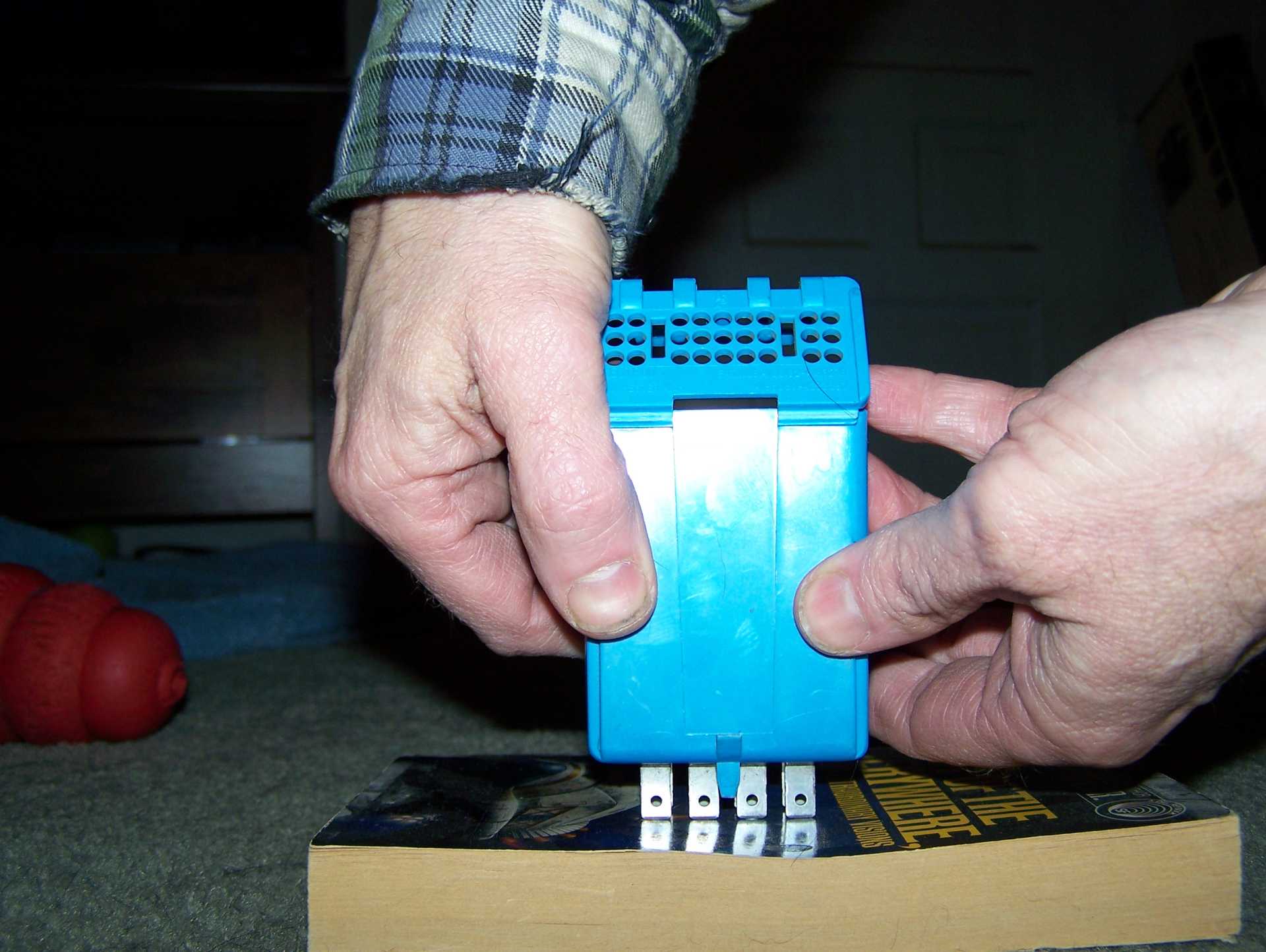
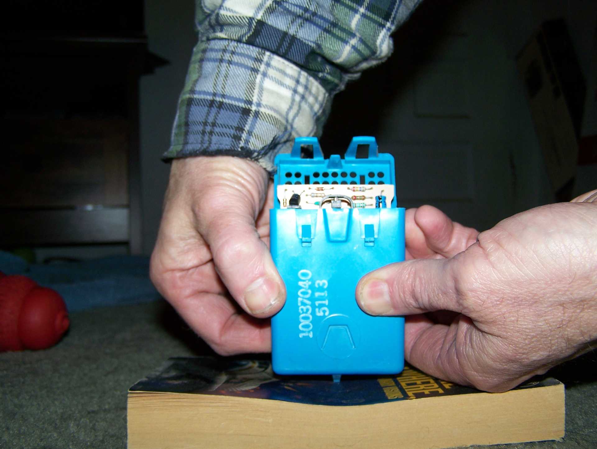
Yes, just carefully push in the terminals to push out the board. Some are tighter then others but all "gen2" units should do same.

 
quote
Originally posted by Dennis LaGrua:
An often overlooked part. On most of the Fieros that I have owned this chime box doesn't work. I wonder if anyone has found a way to repair them?
You read my Cave, Chime Unit then you know biggest problem and how to fix for 15+ years.

All,

"GM" Chime units for many cars fails and often for same reason because same Lectron "boards" are used in Millions of GM vehicle w/ minor changes for car model/year. 
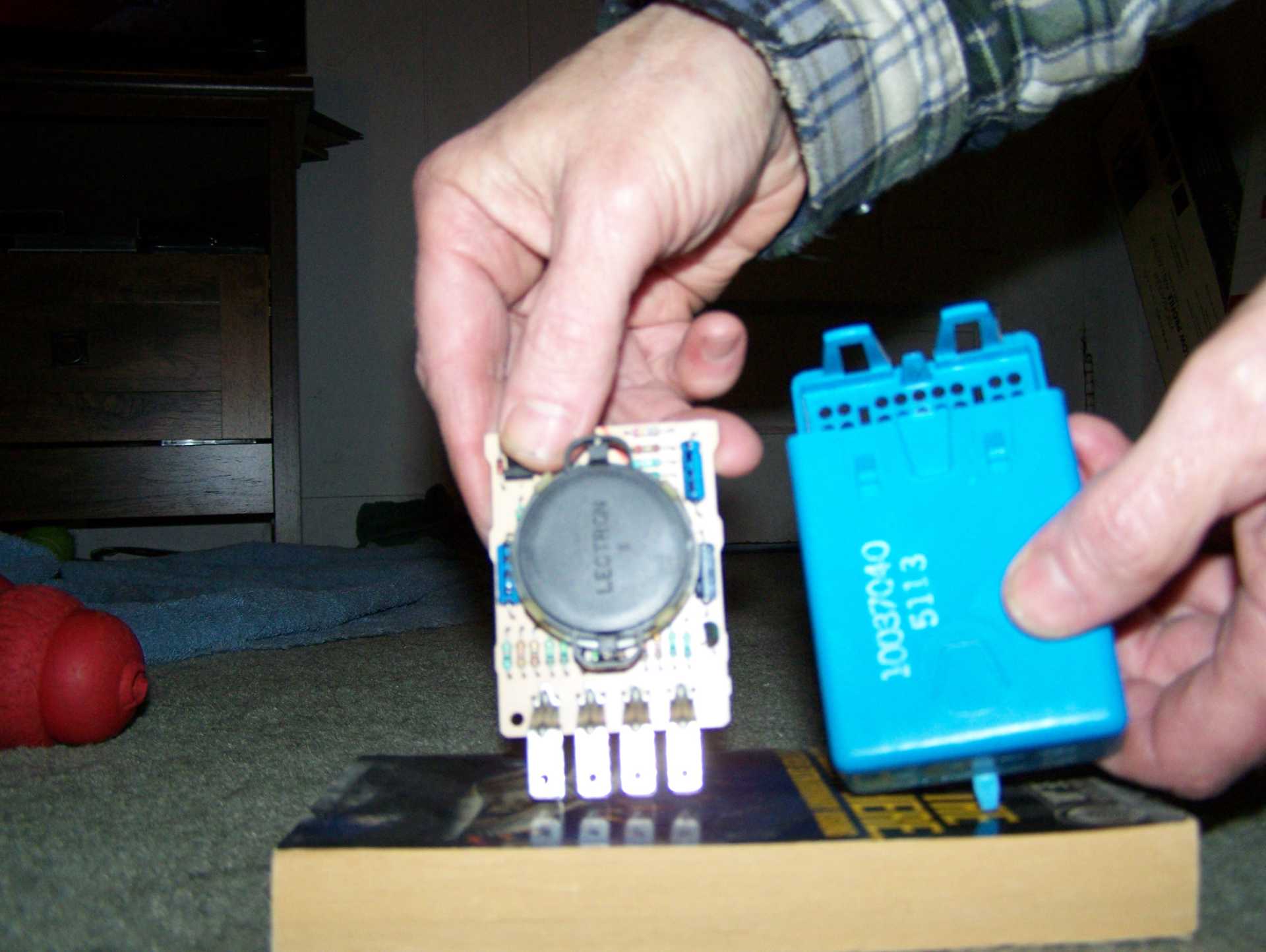
https://www.fiero.nl/forum/F...HTML/143278.html#p17

Heavy metal part of the speaker in used as a jumper w/ all "ears" solder to the board connecting to terminal G/3 main ground.
Metal is too big to wave solder when made plus on "Gen2" unit metal end near terminals the copper on board isn't a closed pad between the two issues solder fails over time. (A bigger complete pad won't fit there.)
Even w/o the weak pad the solder can fail at any/all joints to the speaker "Bridge" part.
May have a crack joint for main terminals but most are cause by the bride not making connections at all solder spots.

Why is this a problem?
Wave Soldering use to make this is hard to setup when 1 heavy part is way bigger then all of parts on the board. Big parts need more time and heat but small parts fail when heated too much. Wave Soldering Machine YT (Board in, preheat oven, wave solder, board exit.)
Incomplete pads won't help and more so when have copper on one side of the board.
SMD Oven/"reflow" soldering now are same way to make nearly everything. Big parts often have weak joints then add RoHS lead free solders that has problems too.

Solder is "easy" enough but need higher Watt iron/gun to do it w/o lifting the trace.
I used 90-120 Weller Gun to quick heat the metal part then move tip to heat trace fast then add Lead base solder. That takes Seconds for small ends a bit more for the middle. Even then Don't touch middle if joint is ok. most issues are on the small bridge ends.

Small irons, under 30w, can take too long to way to long to heat the bridge metal and cause lifting trace(s). Many have Cheap small irons make more issues. Try heating metal first until see most solder melt then touch the trace too to melt the rest fast and quickly add small diameter flux core solder as needed. (small daim like .032" melts faster then most get radio shack et al.)
Even then may heat the metal causing large expansion then could crack the joint when cold.

Do Not use lead free solder needs high heat.
Carefully Remove the speaker box before heating. Loop "ears" clip on the metal and easily break. If broken try hot melt glue.

If this Isn't the problem... Can be anything on the board. A bad chip(s), bad cap, etc. but often not a crack solder joint.
"Gen1" units built as shown in US Patents use a thermistor to make tones. That may die or anything else. "Gen2" less crowded but parts can die.

------------------
Dr. Ian Malcolm: Yeah, but your scientists were so preoccupied with whether or not they could, they didn't stop to think if they should.
(Jurassic Park)


The Ogre's Fiero Cave

IP: Logged

next newest topic | next oldest topic

All times are ET (US)

Post New Topic  Post A Reply
Hop to:

Contact Us | Back To Main Page

Advertizing on PFF | Fiero Parts Vendors
PFF Merchandise | Fiero Gallery | Ogre's Cave
Real-Time Chat | Fiero Related Auctions on eBay


Copyright (c) 1999, C. Pennock