Pennock's Fiero Forum
  Technical Discussion & Questions
  Diagnosing, repairing and calibrating Fuel Sender

Post New Topic  Post A Reply
Email This Page to Someone! | Printable Version


next newest topic | next oldest topic
Diagnosing, repairing and calibrating Fuel Sender by fierobear
Started on: 10-31-2019 04:53 PM
Replies: 1 (213 views)
Last post by: freedom0226 on 11-01-2019 07:21 PM
fierobear
Member
Posts: 27079
From: Safe in the Carolinas
Registered: Aug 2000


Feedback score: (2)
Leave feedback


Total ratings: 383
Rate this member

Report this Post10-31-2019 04:53 PM Click Here to See the Profile for fierobearSend a Private Message to fierobearEdit/Delete MessageReply w/QuoteDirect Link to This Post
Recently Toddster wrote up as part of his Formula restoration the clean up and calibration of the fuel sender unit in the fuel tank. Some details weren't clear to me, so I'll ask my questions here...

1. Where are the contact points on the Torx screws? Is it the flat plate, the very thin wires, or both?


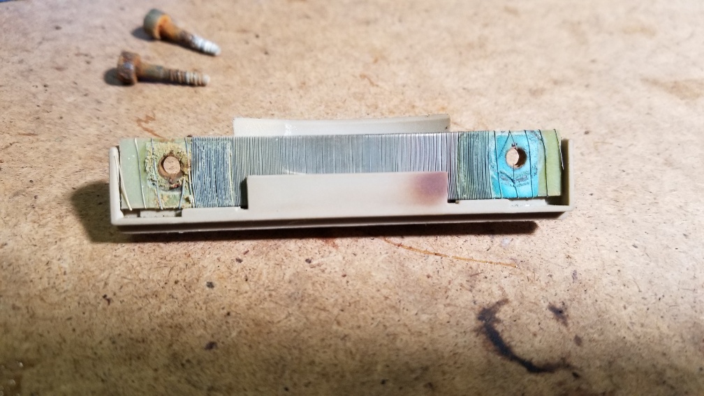
2. How is contact continued from the screws through to main sending wires?


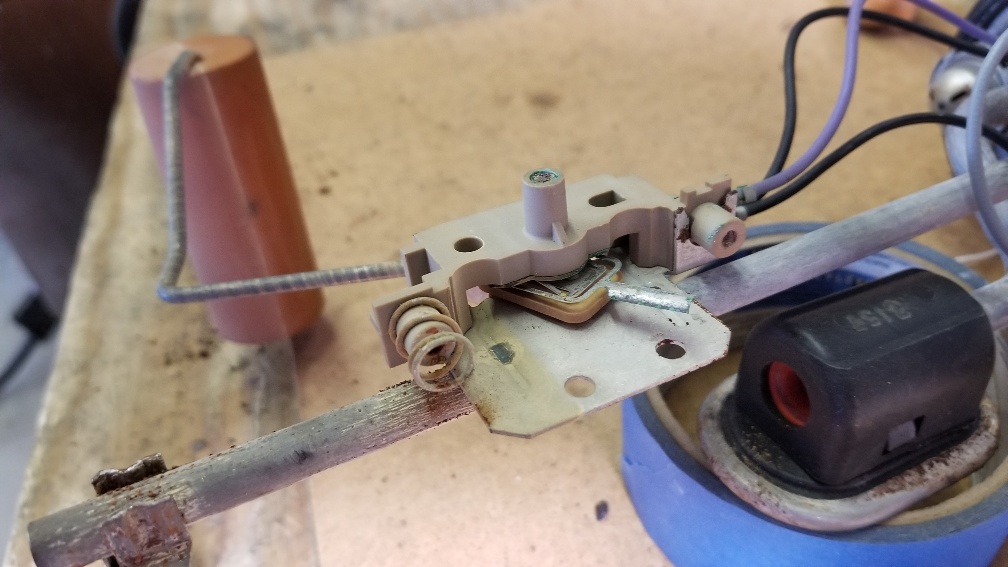
I plan to remove all rust and corrosion from all the parts of the sending unit, then do the calibration. I want to make sure I clean up everything that has corrosion and is preventing a good signal.

On the subject of calibration, how does adjusting the Torx screws affect resistance? Shouldn't there be just one place they can be tightened to? Too tight, they scrape the wires. Too loose, they are an open?
IP: Logged
PFF
System Bot
freedom0226
Member
Posts: 954
From: Compton , California
Registered: Dec 2009


Feedback score:    (10)
Leave feedback

Rate this member

Report this Post11-01-2019 07:21 PM Click Here to See the Profile for freedom0226Send a Private Message to freedom0226Edit/Delete MessageReply w/QuoteDirect Link to This Post
i just did this on my tank. search the archives there is a couple of great step by step instructions on how to do it. first i dip my entire sending unit in vinegar bath for a day or two and try to remove the coil strip as you already did and be verrrrry careful to not brake the copper lines as this will interrupt your readings. lighly try to sand them down with a fine brush or fine sand . if you can clean it all up well and reassemble you should be able to get some ohm readings now 0-90 ohms is the spec. Let me know if you cannot find the older write ups i mentioned and i can send you the link later on. WORST case scneerio you an either pay the $ 250 for a new sending unit from the fiero store OR get a 0-90 unit from ebay for $30 bucks and fabricate it on the OEM sending unit. You will also find a thread on that as well . its been done before. Let me know how i can help you
IP: Logged

next newest topic | next oldest topic

All times are ET (US)

Post New Topic  Post A Reply
Hop to:

Contact Us | Back To Main Page

Advertizing on PFF | Fiero Parts Vendors
PFF Merchandise | Fiero Gallery | Ogre's Cave
Real-Time Chat | Fiero Related Auctions on eBay


Copyright (c) 1999, C. Pennock