I have not posted for a while, but have been lurking occasionally. The last 10 years I've been busy working on hot rods. So I decided to work on a new hot rod project, my 84 SE, Iron Puke, 4 speed and A/C.
The project: 84 SE, 4 speed with original 27,000 miles (45,000kms) 91 TPI 305 ci 1227730 ecm
I have been working on the setup since October 2018 in my heated garage. Let me tell you something, I really appreciate what some of the forum experts have commented about the 84 not being the friendliest to do a swap due to the wiring. WOW, are they ever right. I have high respect for members like and not limited to: Darth Fiero, Fieroflyer, Radar, 1 MohrFiero, olejoedad, RWDPLZ and others that contribute to this great form. The 84 is definitely a unique year, totally different C500 pinout and location, ECM pinout and their respective wire colors. 85 - 88 were closer to each other with some differences. But that did not stop me from forging ahead. KEEP THIS IN MIND. I want to keep the original C500 and relocate it and the original C203. Just re-pin as needed.
7730 wiring harness: The first encounter was the A/C. The 84 has a clutch relay, but the 90-92 f-body does not. I will add some schematics later.
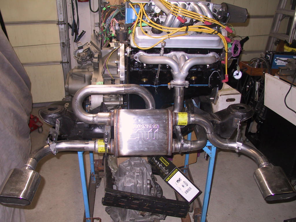
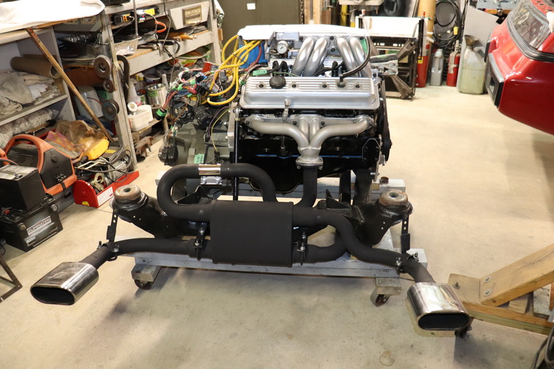
I did a 305 TPI in my 84. The V6 fiero fuel lines will point right up were the F body TPI fuel rails go. I used A set of headers form EBAY. Stainless steel "TURBO HEADERS" on mine. they point to the drivers side, up high. I made a cross over pipe that goes just like the factory v6 cross over pipe. with a elecrtic dump were the fiero had the converter. This connects to the rest of the stock v6 GT exhaust. I had to remove the little shelf in the back trunk to get them to clear. Over the years I have made a lot of changes. I have a 4T60-E with a TCI trans controler. I made a power distrabution point for 12 volts behind the drivers seat to get the fuesable links away from the starter. I have all digital gages so they all work and you can see them. I have 12 inch vet brakes IT STOPS! I have lots of picturs, but can't post them here. I AM on facebook. I am Fredrick W. Hall on there. I have a facebook page fro V8 fieros. "V8fieros". You can see how it runs if you look me up on youtube. Last month I made some runs at a 1.8 mile drag strip. no times, there clocks were not back from calibration. On all the runs I took of in 2nd gear. The trans controler lets me do that. starting with the 3rd run the dump was open. It doesn't have the 305, the TPI, or a flat tappet cam any more. It does have a 357, dart heads, victor intake, comp cams roller cam, roller rockers, K&B pistons, eagle rods, 3.42 gears, 2800 rpm stall. You will need to reinforce the cradle were the front trans mount bolts down. You will need more rad. you will need more brakes. Put a restrition in the heated hose, 1/8 inch will work. This makes the water go to the rad. I CAN post pictures of all this on facebook. The vid on youtube is "Chevy V8 Fiero-7"
[This message has been edited by FFIEROFRED (edited 03-13-2019).]
FFIEROFRED - You wrote, "I did a 305 TPI in my 84. The V6 fiero fuel lines....". I think your car was NOT an 84, because V6 were not available till 85. The fuel inlet and return lines will face the rear glass on mine and I don't expect any issues. My exhaust is done and as soon as I figure out how I used PIP, I'll post pics and other material to support my swap. I don't subscribe to facebook. My car will not be on the track of any sort, just cruising. That's all I can do at 72 years old. Thank you for the input.
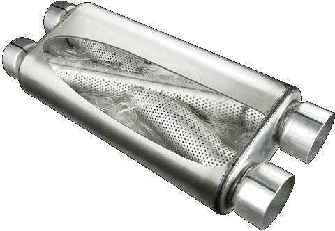
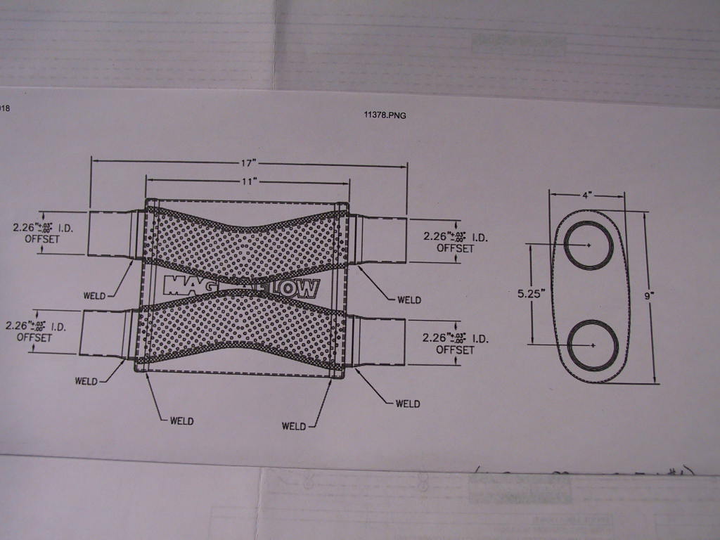
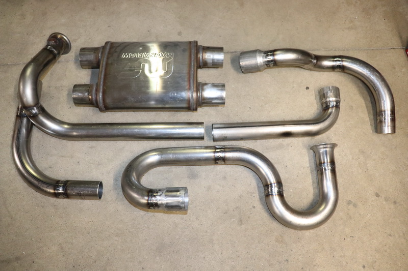
The muffler I'm using is MF 11378, 2 in & 2 out 2-1/4" all ends. It's bi-directional, but the tubes don't cross over. They connect in opposite direction. That is top to top, bottom to bottom.. That's why I have the exhaust welded (spot welded for now) as shown. Had to contact MagnaFlow to ensure the inner works. Yours looks like they cross over. What make and number is it?
The muffler I'm using is MF 11378, 2 in & 2 out 2-1/4" all ends. It's bi-directional, but the tubes don't cross over. They connect in opposite direction. That is top to top, bottom to bottom.. That's why I have the exhaust welded (spot welded for now) as shown. Had to contact MagnaFlow to ensure the inner works. Yours looks like they cross over. What make and number is it?
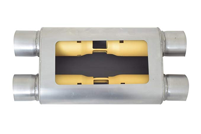
That's just a generic picture of a crossover that some cars have. Yours is obviously like this Gibson design then.
[This message has been edited by fierosound (edited 03-14-2019).]
I may want to recommend this type of exhaust routing to a friend who is doing a Fiero engine swap similar to this one, in that the engine has two manifolds pointing downwards.
[This message has been edited by pmbrunelle (edited 03-14-2019).]
pmbrenelle - No I have not tried it in the car (still on the road) and that's why all the pipes are tack welded. But having said that, I mocked up the walls including the heat shields along pics from my another v8 I did in an 87. I should have more clearance in this one than I did with dual mufflers in the 87. That muffler is 4" x 9" x 11" for the body. I don't know how it's going to sound. Once it's fitted I will remove the bends and finish tigging all the joints. After measuring a stock V6 exhaust, there's actually more clearance with my setup. But proof of the pudding will be in the mock up. That's not for a while yet.
This is the inside of the muffler
[This message has been edited by rubyredfiero (edited 03-15-2019).]
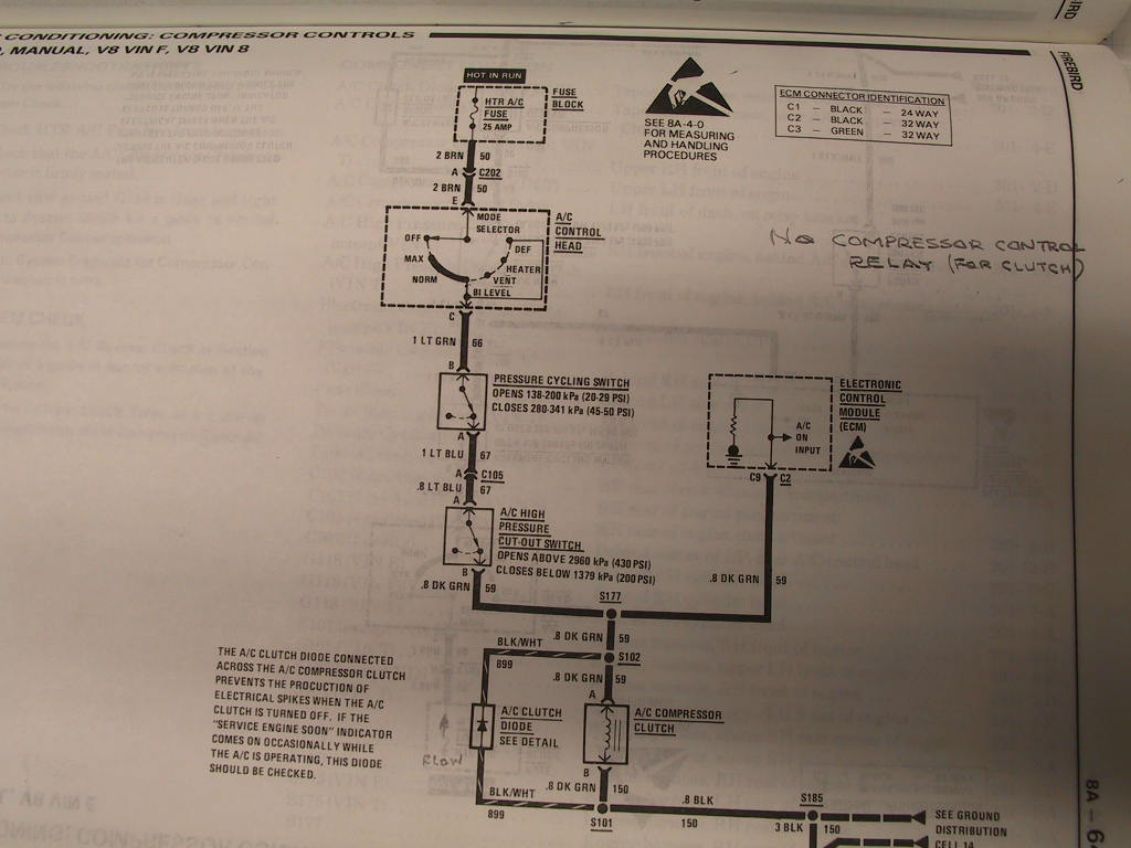
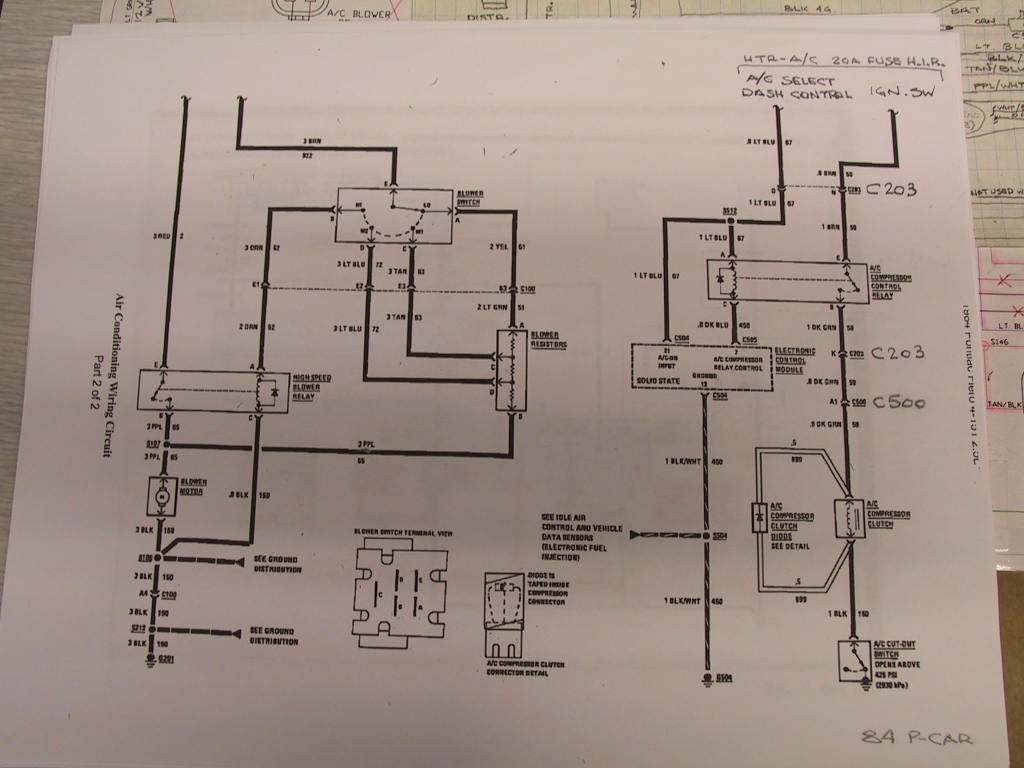
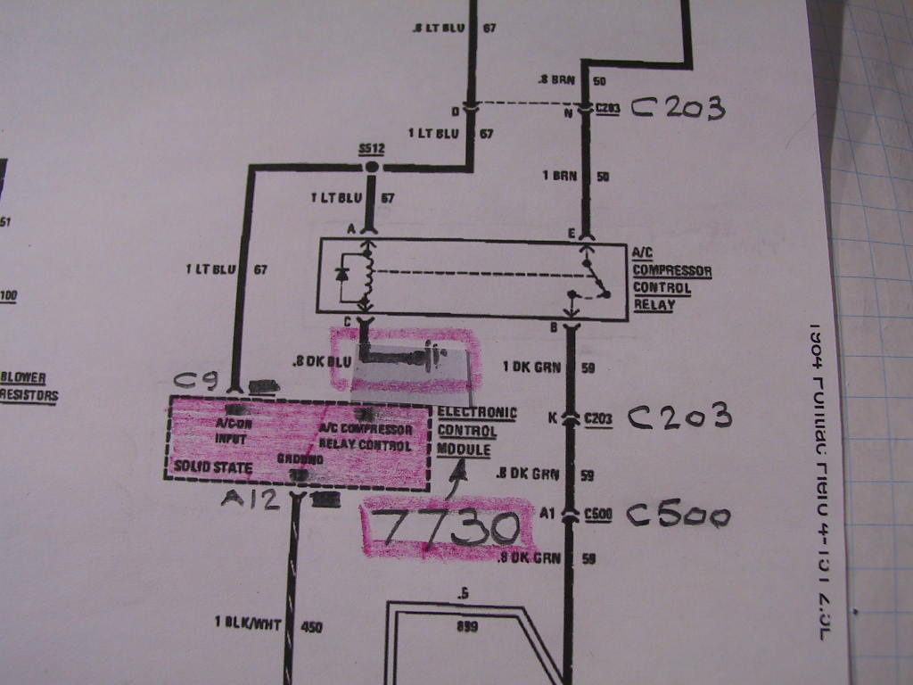
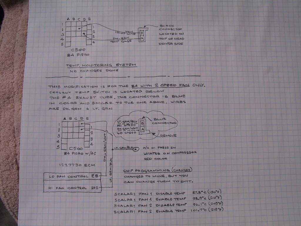
Ok, as mentioned already the A/C system differs quite a lot. Here are the comparisons. Just a reminder, I want to keep the 84 C500 and C203, just do some mods as needed.
The 90-92 7730 A/C is wired without a "A/C Compressor Control Relay" for the compressor clutch.
The 84 Fiero 1226156 A/C is wired with a "A/C Compressor Control Relay" for the compressor clutch.
The 84 A/C circuit. Now if I read this right, when the button is pushed on the HVAC head on our dash and the key is in run, the circuit is completed thru C203 terminal 'D', which tells the ECM A/C was requested via C504 terminal '21'. The ECM supplies ground by connecting C505 '7' to C504 '12' (ground). When the relay coil is energized via terminals 'A' and 'C', the relay's internal switch is made, which completes the circuit via C203 'N', relay terminals 'E' and 'B', C203 'K', C500 'A1', the compressor clutch and finally the A/C Cut-out Switch. Phew, I hope I got that right.
The 7730 circuit. As I study the schematic, there is no place to attach the dark blue wire from the 84 ECM C505 '7'. Since all the ECM supplies the ground I will run the dark blue wire to ground. That circuit will be completed when the button up front is pushed. The red shaded are is the modification.
Please review my methodology and correct me or point out what I missed. Thanks fellows.
I want to send a special thanks to BLOOZBERRY who pm'd me offering any assistance I may need. I already received some schematic info he used when he did his swap that applies to my project. I will first inquire on the forum for peeps to peruse, then if no one responds I will pm individuals for much needed assistance.
Having said (wrote) that, I'm surprised there were no comments on my a/c post. I will now show you what I did for my cooling system. This applies to 84 Fieros with A/C and 2 SPEED rad fan. This is what I did and if you decide to use it, I will not be responsible for the accuracy and you are using my info at your own risk. The schematic is self explanatory especially the "CHIP PROGRAMMING (changes)" which is required to complete my swap.
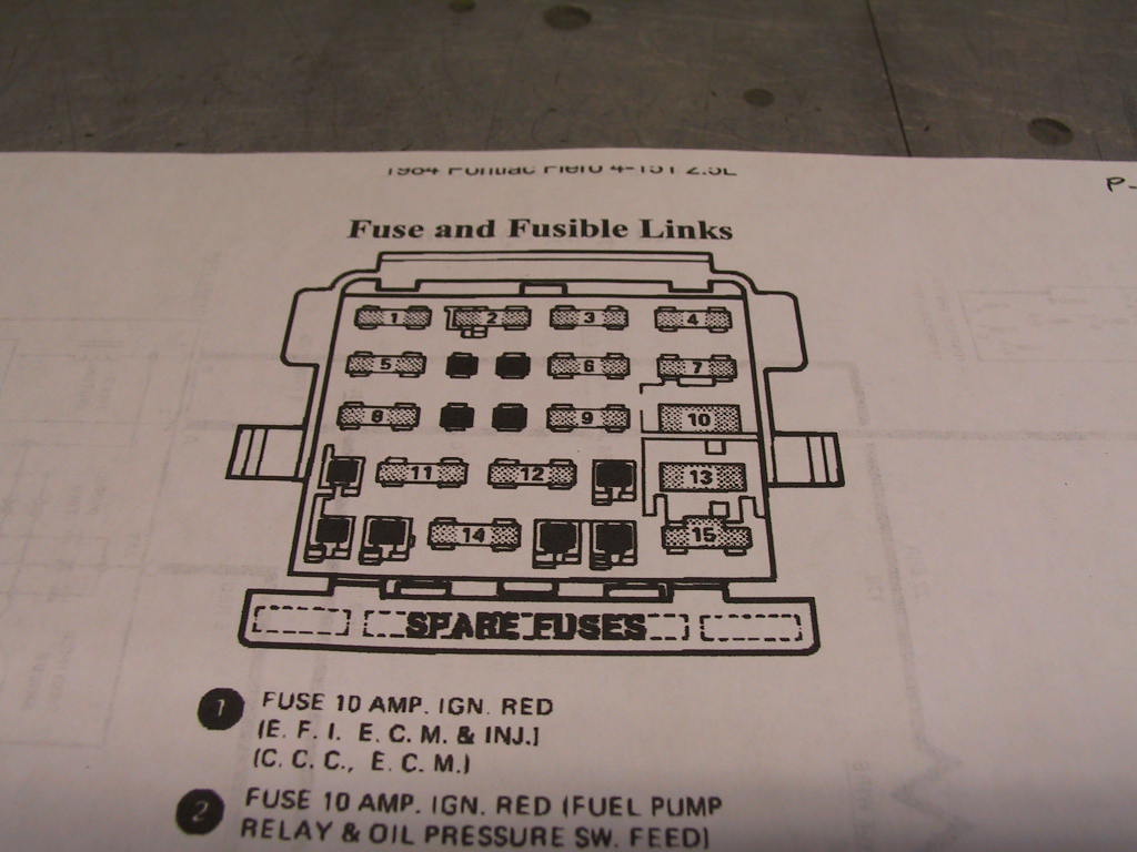
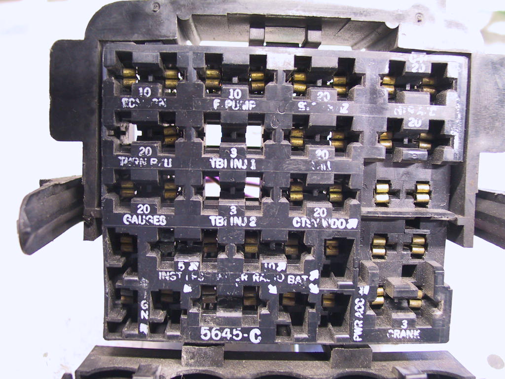
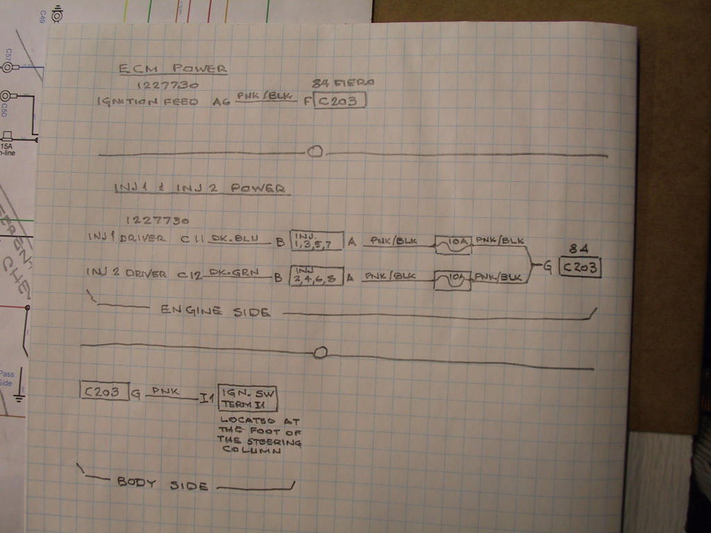
This is what I did for fuses to supply INJ 1 and INJ 2 power, and ECM power.
ECM power feed. The 84 fuse box has Fuse #1 for the ECM power feed. Connector C203 Terminal "F" has the wire Pnk/Blk that I connected to ECM 7730 pin "A6" for the ECM power feed.
INJ 1 and INJ 2 power. If you look at the pic of the fuse box, fuse locations between #5 and #6 is blank, so is between #8 and #9. There are no terminals or wires at the back of the fuse box to insert a fuse.
In the 84, C203 'G' is blank. So I spliced a 12Ga Pnk wire from the ignition switch (white switch a the bottom of the column) pink wire at terminal I1 (ign #1) to the body side C203 'G' using wires with their respective terminals from donor harnesses. From the engine side C203 'G' I spliced 2 inline fuses. One for each, inj 1 and inj 2. Then ran one fused wire to ECM 7730 'C11' for INJ1 and the other fused wire to ECM 7730 'C12" for INJ2.
It sure would be nice to see some feedback. Thanks.
Nothing wiring-wise looks too crazy, though I do have constructive criticism (you did ask for feedback).
Pnk wire G is not fused according to best practices.
Normally, wires are fused as far upstream as possible, to protect against shorts to ground along the length of the wire. Fuses only protect the portion of the wire that lies downstream of the fuse; the upstream part is not protected. You presently have a long run that is unprotected against shorts.
Therefore, it is recommended that you add a fuse inline with Pnk wire G, as close as practical to the ignition switch. The fuse shall be sized (ampere rating, see automotive chassis wiring ampacity tables such as https://www.littelfuse.com/...lfuse_fuseology.pdf) to blow at a current below the current that would cause the 12-gauge wire to smolder and catch the car on fire.
If you think the resulting fuse rating will cause nuisance blowing, that just means you undersized the wire.
pmbrunelle - Thanks for the response. I followed the pink wire that I will be splicing to, by referring to FSM for the 84 Fiero. That wire starts at the 'BAT' terminal on the starter, immediately through fuselink A red wire, to C500 terminal 'E4' all the way to the front to splice 'S206', then to the IGN switch terminal 'B3'. When the switch is crank/run it connects 'B3' to 'I1' (eye1). From IGN switch 'I1' on, it's pink through C500 'E3' to the coil's gray connector terminal 'B'. Now unless I missed something, that pink wire runs from the IGN switch all the way to the coil without a fuse in between. Instead of splicing into the coil's pink wire to avoid the extra demand on the wire, I chose to splice into the wire at the IGN switch 'I1" and run 2 in-line fuses for INJ 1 and INJ 2.
Very cool. I've had a TPI swapped 87 GT for a few years now, from An 87 GTA. Its a 5 speed getrag. It was an old swap by someone else and I have got most of the lack of maintenance done, and fixed some things, improved / removed a few things, added a few. Driven it all over and made it home. I'll be watching your thread. For A/C this one has the V4 from the 4 cyl fiero on it. Good luck and keep on
[This message has been edited by 2.5 (edited 04-04-2019).]
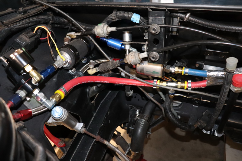
Some of the preparations I had to do before the drive train was installed, the stock fuel lines were cut and AN to hard line fittings installed. I kept the stock TBI fuel pump and added an external Walbro in-line electric pump. KEY WORD is only 25,000 miles on the car. Since any external pump needs to be below the tank to avoid cavitation, the TBI pump will provide a max of 14 PSI to feed the external pump. The external pump is regulated to provide 50 PSI and the TPI regulator provides 42-43 PSI to the injectors. Both regulator's return lines (red) are teed to the original return line going back to the tank. The external pump has it's own relay and is spliced with the stock relay so as both have the 2 second key-on run. It works great. The stock 3/8" line goes to a Russel 40 micron filter (blue), to the Walbro pump, to the regulator, through a steel braided line (somewhat hidden), through the stock type filter 10 micron and through the blue hose (300PSI burst) to the fuel rail.
[This message has been edited by rubyredfiero (edited 06-22-2020).]
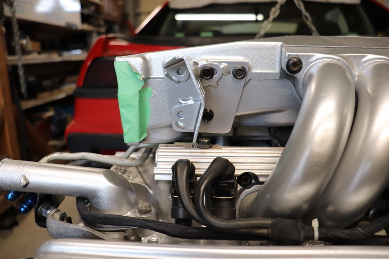
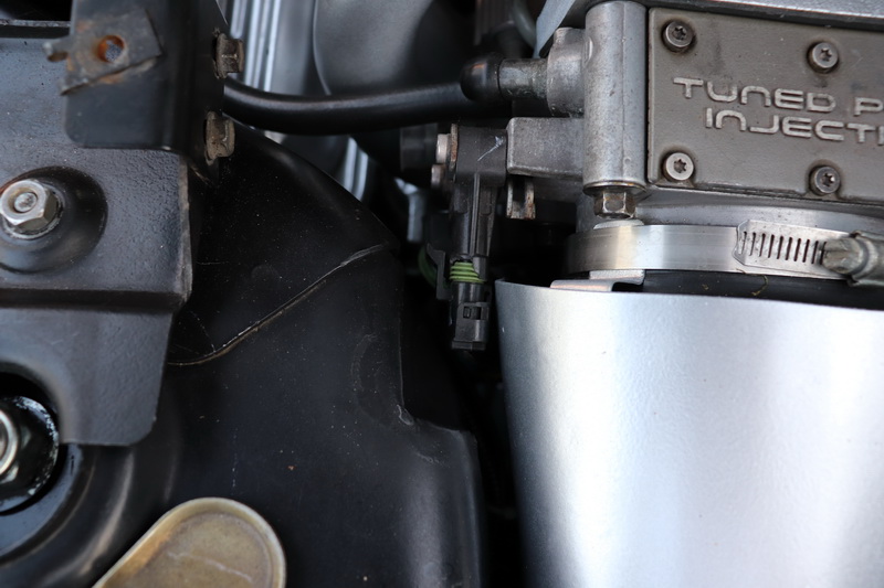
It's very hard to see the C500 just behind the red/blue fuel lines. I moved the C500 over to the driver's side about 9" without any modifications to the original wires. You can see the tail lights harness plug resting on the AC pipes which were left in the stock location.
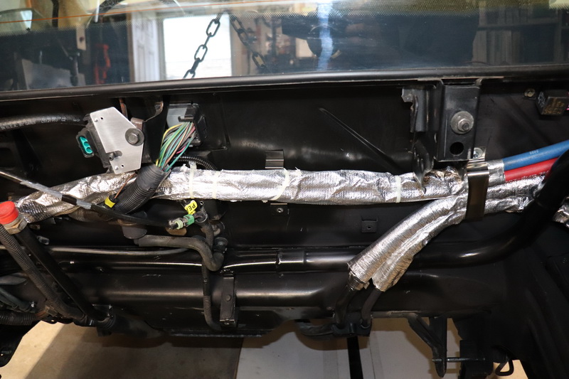
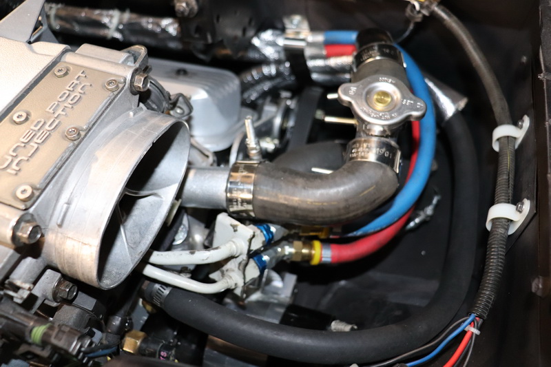
This next pic shows the fuel hoses and the heater hoses are wrapped in heat socks to prevent excessive heat generated by the headers. The heater hoses were moved over towards the pass side about 4" to clear the header collector. Also the coolant cross over pipe from the thermostat housing to the driver's side is sitting on the ledge and bolted down. Made from bends and straights, tig welded and painted. Deck lid torque springs were removed and pass side hinge cut down.
I was able to use the stock 4 cylinder gas pedal cable by moving the stock TPI cable bracket over to the next hole. Except there is no 4th hole to use, so I made a flat plate and welded the TPI bracket to it and drill 3 holes in the late. I think it ended up being 1.25" over. Works great and get full travel at the pedal.
Nice job and a pretty fancy exhaust system. I would just not drive it hard as the transmission was designed for 200 ft lbs of torque.
------------------ " THE BLACK PARALYZER" -87GT 3800SC Series III engine, custom ZZP /Frozen Boost Intercooler setup, 3.4" Pulley, Northstar TB, LS1 MAF, 3" Spintech/Hedman Exhaust, P-log Manifold, Autolite 104's, MSD wires, Custom CAI, 4T65eHD w. custom axles, Champion Radiator, S10 Brake Booster, HP Tuners VCM Suite. "THE COLUSSUS" 87GT - ALL OUT 3.4L Turbocharged engine, Garrett Hybrid Turbo, MSD ign., modified TH125H " ON THE LOOSE WITHOUT THE JUICE "
Dennis - Thanks for the compliment. Yeah, I'm aware of the weak point. My aggressive days are behind me. At 72 I'm just happy I can still work on cars. It's my daily cruiser and have a 1936 Chev hot rod for car shows.
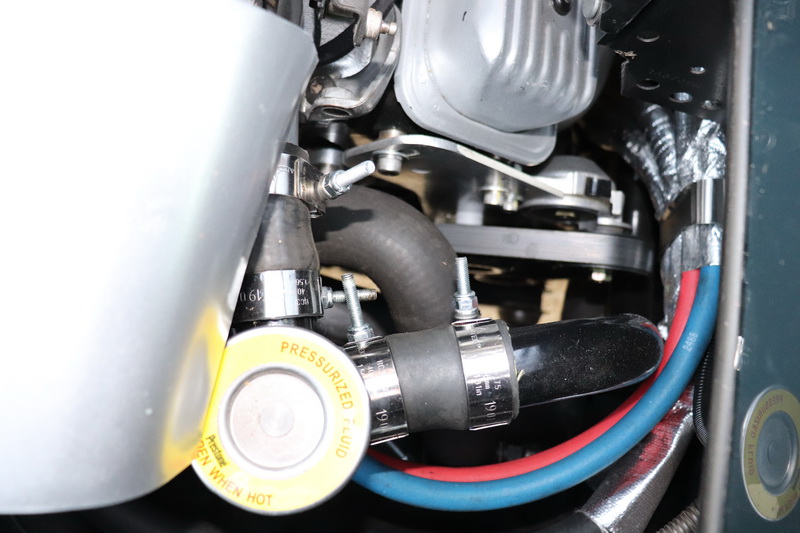
After I installed the filler neck from the thermostat housing to the coolant cross over pipe, I was not happy with the looks of the hoses.
The hoses, short as they were, were under stress. I put a piece of cardboard under the hoses for clarity. You can really see the bulges in the connections.
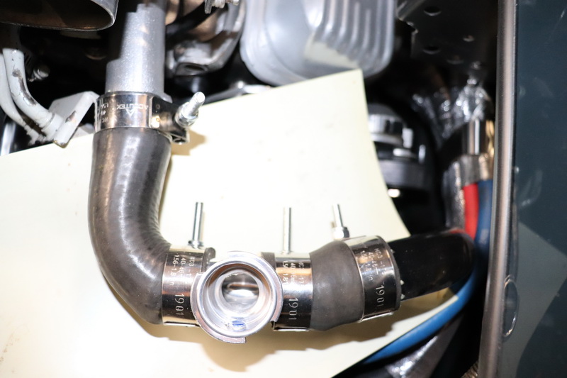
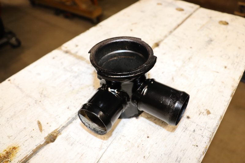
So I modified a 4 cyl. filler neck by cutting the bottom part, welded it shut and added a tube connection.
This is what it looks like installed.
The best part is the stock RC40 can be used instead of the small filler neck cap which only had a 7/8" opening to pour the coolant.
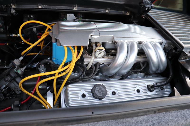
With everything in place the engine just clears the vents. Notice the cone filter sits just under the grill and will get soaked when it rains or I wash the car. If you look in the previous pic, you will see I made a shield that wraps the top half of the filter.
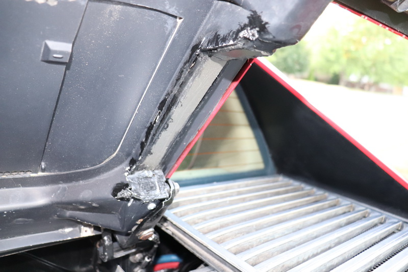
Remember the car is an 84. In order to use the original deck lid with the solid side covers and the wide center grille, too much cutting was required. I used an 85 and up deck lid, donated by my good friend from London, Ont, Arns85GT. The pic shows the section removed and reinforced with 1.25" square tubing welded to 0.5" x 1.25" bar as far as I can swing into place.
A gas strut shock holds the deck lid open on the driver's side.
It drives great. I put in 350 LBS spring to reduce rear bump steer, because there's no sway bar in the rear. I thought it would be rough, but no. Maybe because there's new KYBs all around. It's no family car.
Yes it's pretty solid. If you look at the pic in my 06-22-2020 12:59 PM post above, there's a strut bar with heim joints at each end, from the back of the head to the engine cradle and all the mounts are solid. I checked it by stuffing Plasticine putty between the TPS and the tower and all is good. Thanks for the input.
Good work mate!!! I'm very fond of the TPI system. I used to hopped them 305's that beat 350's every night! That's the reason I built my manifolds the way I do, there's some TPI DNA in my intakes! Best wishes!