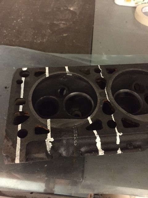
I did have plans to port the heads while the engine is in pieces..
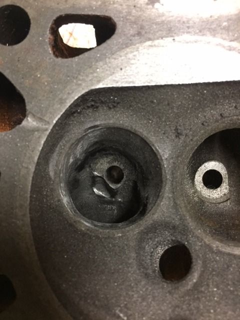
The intake ports are typical GM 80s design, in this case steering the flow upwards and sideways via the blob in the middle of the passage, somewhat like the swirl ports on the 350 smallblocks(TBI version) althoug the intention of that one was creating a vortec.
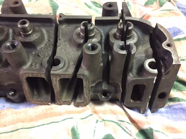
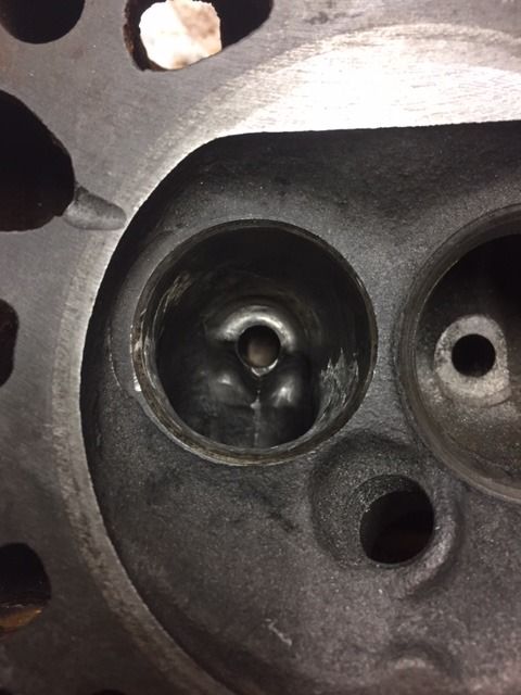
the exhaust port definetly looks worse than the intake, the runner is not straight (at all) and there is a hump blocking the flow. This is probably a consequence of the spark plug location interfering with the exhaust port. Hmm
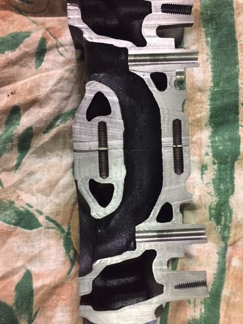
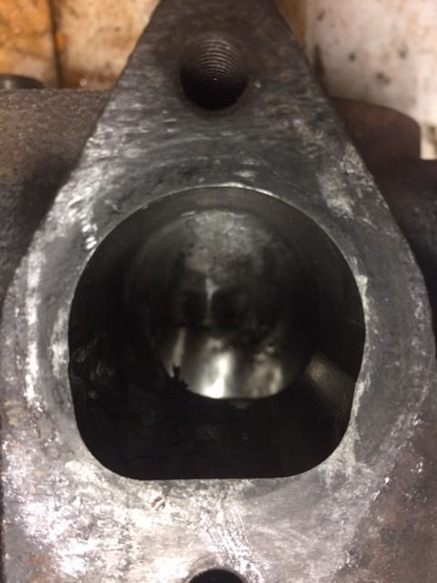
And this is what happens when trying to machine the hump to flatness.. and shape the port to a modern D-shape.
The extruding part of the hump is the wall, there is no additional metal behind it.. Everything looked ok until the last pass in the mill but Im glad I found out, otherwise I would have walls as thin as a hair out to the coolant. That would have been a catastrophe waiting to happen.. So heads up for that one if you plan to port these heads.
What you did with the exhaust port looks similar to how I ported mine. My main goal was to create a flat floor in the exhaust port, from the valve bowl out to the header. And as you mentioned, one has to be careful not to cut into a water passage, or the spark plug recess.
On the intake, don't remove that fin in the center. This seems counter-intuitive, but that fin increases flow by about 15%. That said, it might be a good idea to sharpen the leading edge, to reduce aero drag. There are some gains to be made from smoothing out the valve guide area. There are big hunks of metal sticking out into the airflow path. Plus the transition from valve bowl to runner is pretty ugly.
[This message has been edited by Blacktree (edited 11-25-2018).]
Great to see some pictures of other porting jobs and hear your experinece of this! Yes the runner tilts approx 7 degrees sideways so cutting at that angle would probably been better but then I have to watch the opposite wall instead :/ I may try somewhere between...
Originally posted by Will: Looks like they didn't even touch the injector bosses.
This was a Darrell Morse porting job. Probably one of the last ones he did.
The edge of the port used to block one side of the "spray cone" very badly. It is very much unshrouded from how is was. (Wish I had a pic of a stock intake.)
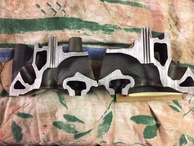
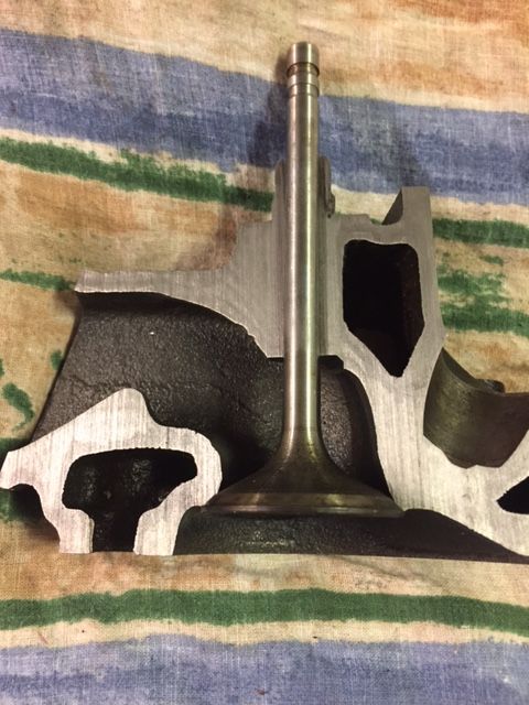
Here is the exhaust port, sorry about the rotation of this picture, i did change it to horizontal but somehow its vertical again..
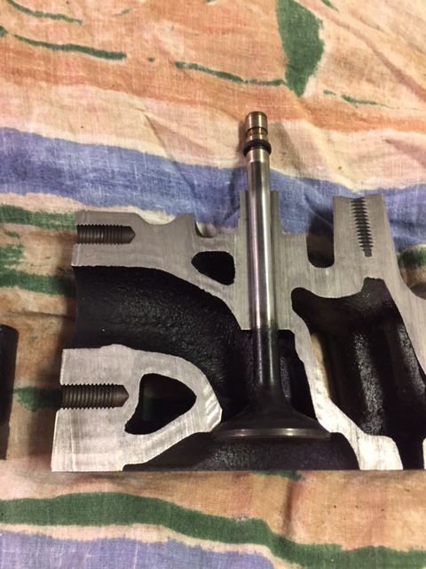
ant the intake port
Note that this is the centre cut from a circular X-section, so it may look likes more metal than it actually is on some places. I do think i hit the cente line of the ports pretty good.
Thin cast design and water channels everywhere.. It will be a challenge to make any major changes of the ports, but trimming and minor adjustments looks quite easy. Its nice to see the pictures of other ports, and the la fiera dyno looks promising for modifying this engine!
Here is the exhaust port, sorry about the rotation of this picture, i did change it to horizontal but somehow its vertical again..
ant the intake port
Note that this is the centre cut from a circular X-section, so it may look likes more metal than it actually is on some places. I do think i hit the cente line of the ports pretty good.
On the intake: most people will look at this and think that bump is a restriction but it's just the vane to divert air around the valve stem...
[This message has been edited by lou_dias (edited 12-03-2018).]
Those cross sections are amazing! So looking at the restrictions, sharp edges, and very rough surface finish, what do you think is more important, Porting or Polishing???
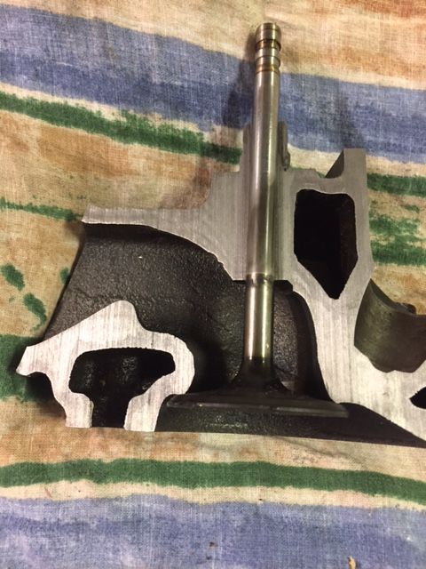
Chevy small block intake valve 1.94" As the picture shows, there is no possibility to clear the throat enough to match this valve diameter..
Chevy small block exhaust valve 1.5"
Similar stems, diamter is the same but the chevy is slightly longer. You can not have 1.94" and 1.5" at the same time, they collide. One OR the other together with fiero size is (probably..) fine.
Originally posted by Notorio: Those cross sections are amazing! So looking at the restrictions, sharp edges, and very rough surface finish, what do you think is more important, Porting or Polishing???
On these heads, the ports need to be reshaped for better flow. If you just polish the existing (crappy) port shape, you're not going to get much.
I did a temporary fix on the hole (see above) in the exhaust port and smoothed the edges of the cut for some flow research..
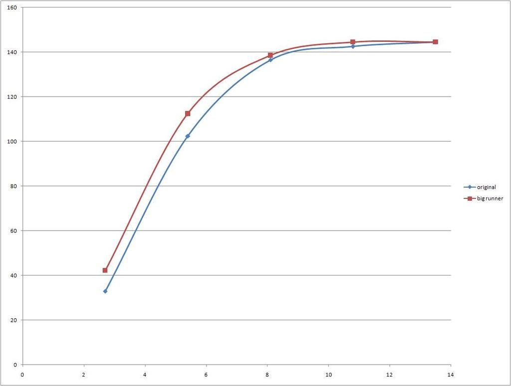
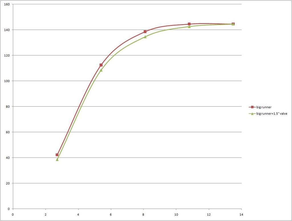
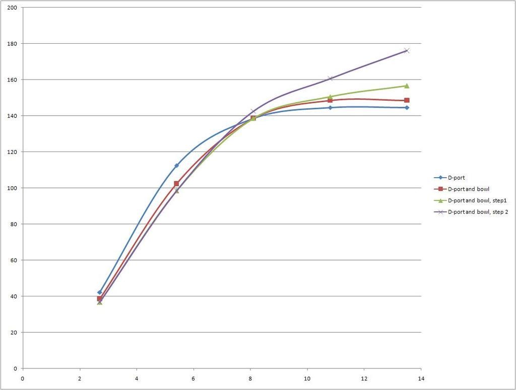
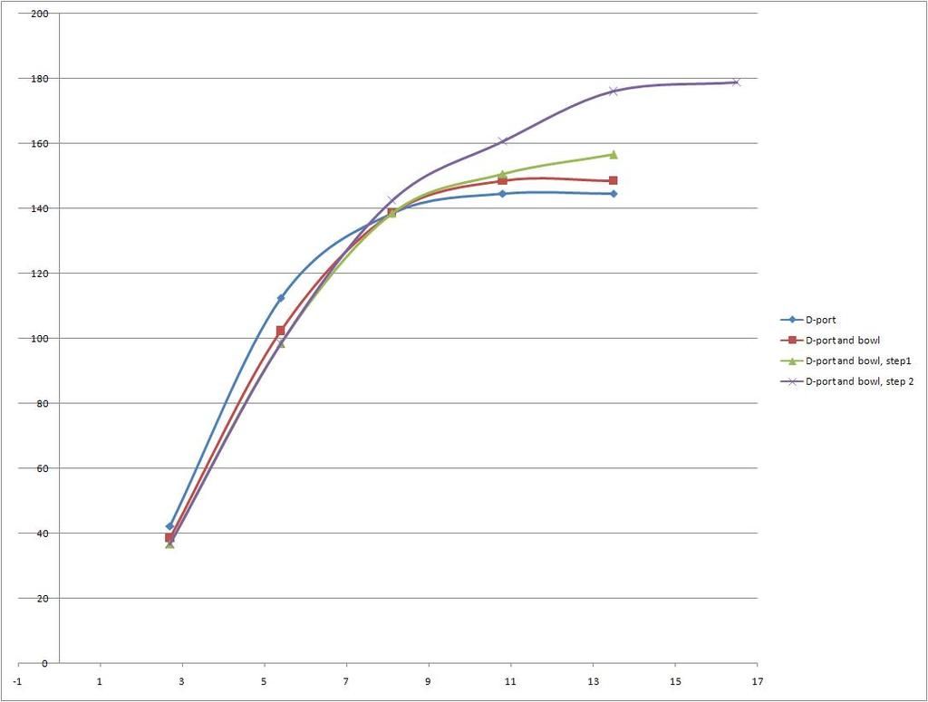
Vertical axis=CFM at 28" water Horizontal axis=mm valve lift (25.4mm is 1inch) Im note 100% sure of absolute values since the flow bench is not calibrated but relative values (comparisons in the same set up) are accurate, and this is what I want to measure.
This is original exhaust port compared the widened port. Note only 1/3 of the total port length is widened so far..
After that I replaced the 1.42" valve with the 1.5" valve without any of the necessary modifications, slightly worse as expected.
Finally I reversed the valve upside down with only the stem in the exhaust port to see if the valve itself is a restriction at max lift, the conclusion is that it is not at these flows.
This is after removing som metal in the bowl area with CNC machine (only 3 axis so some manual Dremel machining follows below.)
And starting to clean up edges
Next step of cleaning and restoring some of the inner radius shape that got lost during material removal
All ends up in these flow numbers. Im kind of annoyed with the loss of low lift flow but the peak numbers ( @ 0.53" valve lift) are up 32CFM from the original standard port and the last version of the modified port would climb even higher with more pressure.
It's not clear to me from the pictures ... how much of the valve guide did you remove? In the heads I'm doing I just smoothed the sharp edges into a radius, with not very much material removed.
It's not clear to me from the pictures ... how much of the valve guide did you remove? In the heads I'm doing I just smoothed the sharp edges into a radius, with not very much material removed.
I removed half of the valve guide, the outer half was shaped into a steep slope. Nice to see someone is reading BTW if you smoothen the bowl and keeping the stock shape it is probably a good idea not to touch the area just above the valve guide, there is a small hump there. I think it is to improve the flow past the valve guide. It may be seen in the cosscuts pictures.
[This message has been edited by lordfiero (edited 01-27-2019).]