Pennock's Fiero Forum
  Technical Discussion & Questions
  V6 iron cylinder head (Page 2)

Post New Topic  Post A Reply
Email This Page to Someone! | Printable Version

This topic is 3 pages long:  1   2   3 
Previous Page | Next Page
next newest topic | next oldest topic
V6 iron cylinder head by lordfiero
Started on: 11-25-2018 10:34 AM
Replies: 115 (3515 views)
Last post by: lou_dias on 07-07-2019 02:27 PM
Blacktree
Member
Posts: 20770
From: Central Florida
Registered: Dec 2001


Feedback score:    (12)
Leave feedback


Total ratings: 350
Rate this member

Report this Post01-28-2019 03:06 PM Click Here to See the Profile for BlacktreeClick Here to visit Blacktree's HomePageSend a Private Message to BlacktreeEdit/Delete MessageReply w/QuoteDirect Link to This Post
That looks pretty promising for high-lift camshafts.
IP: Logged
lou_dias
Member
Posts: 5256
From: Warwick, RI
Registered: Jun 2000


Feedback score: (3)
Leave feedback


Total ratings: 67
Rate this member

Report this Post01-28-2019 09:23 PM Click Here to See the Profile for lou_diasSend a Private Message to lou_diasEdit/Delete MessageReply w/QuoteDirect Link to This Post
https://www.summitracing.com/parts/slp-v-4644

What do you guys think of machining down this valve? It's 0.119" taller than the stock 1.72" valve. I was thinking about getting it down to 1.8" in diameter and then shaving it to between 4.75" and 4.8" then machining it for flow as well as narrowing the valve stem near the opening to 6.5mm... Then also opening the port a hair more to match...
I picked this valve because it will work with the Fiero valve guides (etc..) and it's super cheap...

[This message has been edited by lou_dias (edited 01-28-2019).]

IP: Logged
lordfiero
Member
Posts: 53
From: EU
Registered: Nov 2018


Feedback score: N/A
Leave feedback

Rate this member

Report this Post01-31-2019 07:39 AM Click Here to See the Profile for lordfieroSend a Private Message to lordfieroEdit/Delete MessageReply w/QuoteDirect Link to This Post
 
quote
Originally posted by lou_dias:

https://www.summitracing.com/parts/slp-v-4644

What do you guys think of machining down this valve? It's 0.119" taller than the stock 1.72" valve. I was thinking about getting it down to 1.8" in diameter and then shaving it to between 4.75" and 4.8" then machining it for flow as well as narrowing the valve stem near the opening to 6.5mm... Then also opening the port a hair more to match...
I picked this valve because it will work with the Fiero valve guides (etc..) and it's super cheap...


Check the stem diameter.. My fiero heads have 8,7mm, so look for 11/32" or 0.344" . If you use CSB valves you will probably have to use longer pushrods and spring spacers.
You can find 0.344" with undercut/narrow stems ends from summit, ebay or other places.
IP: Logged
Blacktree
Member
Posts: 20770
From: Central Florida
Registered: Dec 2001


Feedback score:    (12)
Leave feedback


Total ratings: 350
Rate this member

Report this Post01-31-2019 06:45 PM Click Here to See the Profile for BlacktreeClick Here to visit Blacktree's HomePageSend a Private Message to BlacktreeEdit/Delete MessageReply w/QuoteDirect Link to This Post
Yes, the iron heads use 11/32" diameter valve stems. The aluminum heads use 8mm.
IP: Logged
lou_dias
Member
Posts: 5256
From: Warwick, RI
Registered: Jun 2000


Feedback score: (3)
Leave feedback


Total ratings: 67
Rate this member

Report this Post02-01-2019 04:57 PM Click Here to See the Profile for lou_diasSend a Private Message to lou_diasEdit/Delete MessageReply w/QuoteDirect Link to This Post
Ah yes, valve stem diameter is one of those "hi-tech" reasons aluminum heads flow better. Have you guys ever seen the valve stem diameters of foreign engines?

https://www.summitracing.co...t-21471800/overview/
So I guess these wouldn't be cost effective...
IP: Logged
lordfiero
Member
Posts: 53
From: EU
Registered: Nov 2018


Feedback score: N/A
Leave feedback

Rate this member

Report this Post02-06-2019 03:26 PM Click Here to See the Profile for lordfieroSend a Private Message to lordfieroEdit/Delete MessageReply w/QuoteDirect Link to This Post
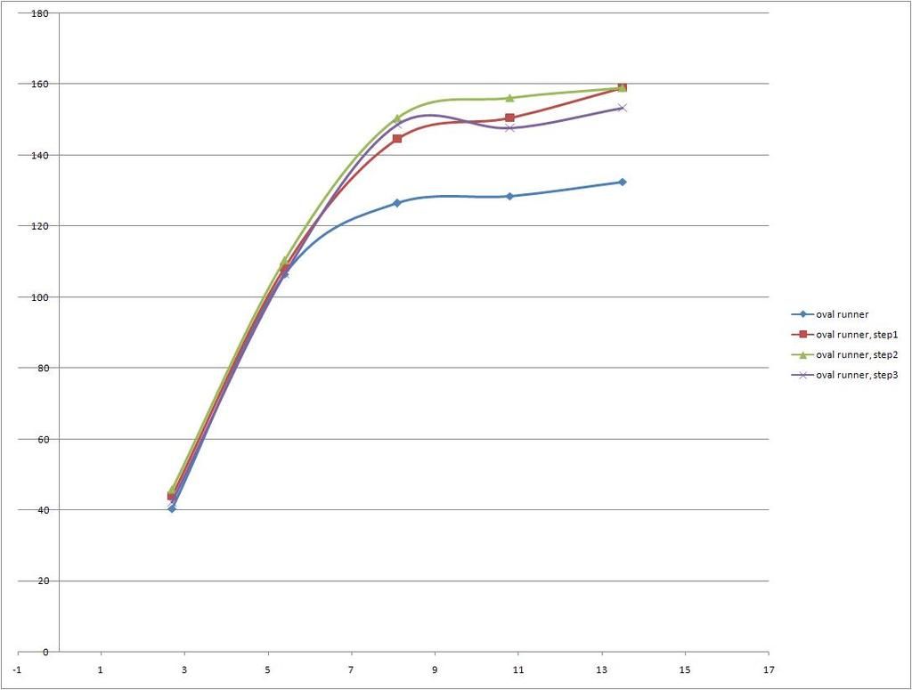
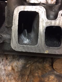
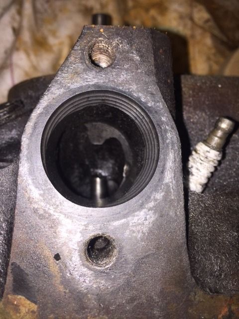
Time to put the D-shape to rest, it was taking to much metal from the walls.
The next step is the oval shape (higher than wide) with a circular conical port opening matching the gasket of 34mm diameter.

Oval shape runner material removal


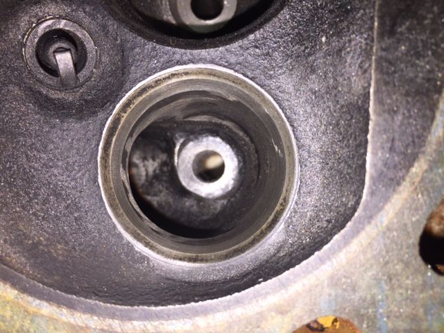
Oval shape runner step 1, rounding of corners and smoothing the surface


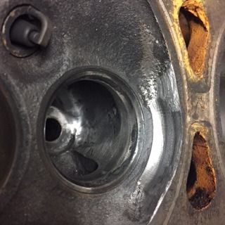
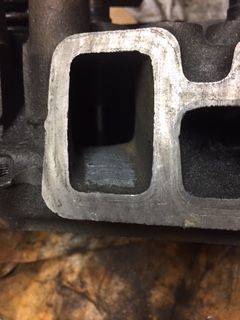
Nothing is done to the bowl more than removing som dirt.


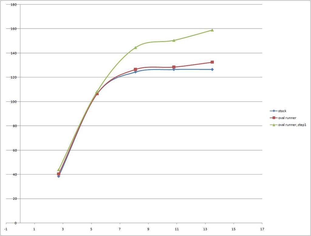
This is the flow, notice this stock port started out approx 20cfm less than the last port used for the D-shape. The area around the valve guide are slightly different on all ports on these heads which results in different flow of the ports, the amount of dirt in the stock ports do vary also..


Im very pleased with the shape of step1, it exceeds the flow of the stock port on all valve lift points and the healthy max flow can be reached with a medium performance cam and high ratio lifters.
IP: Logged
lordfiero
Member
Posts: 53
From: EU
Registered: Nov 2018


Feedback score: N/A
Leave feedback

Rate this member

Report this Post02-07-2019 06:09 PM Click Here to See the Profile for lordfieroSend a Private Message to lordfieroEdit/Delete MessageReply w/QuoteDirect Link to This Post
Step 2
Some quick polishing to the runner surface and removing the sharp (very small) edges where the valve guids meets the bowl, the flow is slightly increased

Step 3
Starting to cut down the valve guide to make a smooth, more flat and even surface, and better looking port just as porting guides describes well yeah.. in my ports this is a recipee for decreased perfomance, the flow dissapears fast. Just like I experienced in the previous D-port design. This is a good thing since reshaping the valve guide would be the most difficult part of the porting job.


So after a couple of months digging and measuring in these exhaust ports I do think the oval port step2 is pretty much as good as it gets, and Im running out of cylinder heads.

Conclusion
Massive gains in the exhaust ports flow can be achieved, with stock valves. These steps did improve the flow without side effects.
Increase the runner, more straight and more area, stay away from the hump.
Round over all edges from the bowl into the runner
Clean up the edges around the valve guide
Polish the new shaped port

The bend between the runner and bowl is what limits the maximum flow, this is why the graphs takes a jump when smoothing out the edges leading to the runner.

Following modifications are according to my studies, questionable
Larger valves, There is not enough metal to remove to fit them
Reshaping the bowl, loss of flow with realistic valve lifts, although very high max flow could be seen.
just polishing the stock shape port, gains to small to justify the time to do it. If not the heads are removed from the car for other reasons.

Now I have to make 6 identical ports..
IP: Logged
lou_dias
Member
Posts: 5256
From: Warwick, RI
Registered: Jun 2000


Feedback score: (3)
Leave feedback


Total ratings: 67
Rate this member

Report this Post02-10-2019 03:18 PM Click Here to See the Profile for lou_diasSend a Private Message to lou_diasEdit/Delete MessageReply w/QuoteDirect Link to This Post
Looking back to an older picture of one of my sets of heads it seems my guy did do some work on the guides as well...

This images is larger than 153600 bytes. Click to view.

IP: Logged
lou_dias
Member
Posts: 5256
From: Warwick, RI
Registered: Jun 2000


Feedback score: (3)
Leave feedback


Total ratings: 67
Rate this member

Report this Post02-11-2019 06:59 PM Click Here to See the Profile for lou_diasSend a Private Message to lou_diasEdit/Delete MessageReply w/QuoteDirect Link to This Post
This images is larger than 153600 bytes. Click to view.
IP: Logged
lordfiero
Member
Posts: 53
From: EU
Registered: Nov 2018


Feedback score: N/A
Leave feedback

Rate this member

Report this Post02-13-2019 12:31 PM Click Here to See the Profile for lordfieroSend a Private Message to lordfieroEdit/Delete MessageReply w/QuoteDirect Link to This Post
You may have lost some of the improvements with the porting job by doing the valveguides smaller. But really hard to tell without flow bench measuring..
I suspect this is the reason for the very small gains in previous published porting jobs on these heads, on this and other forums.

I even tested to grind one of the valve guides down and used epoxi filler to get a perfect flat surface, it looked very nice and "high flowing", but it reduced the flow.
IP: Logged
lou_dias
Member
Posts: 5256
From: Warwick, RI
Registered: Jun 2000


Feedback score: (3)
Leave feedback


Total ratings: 67
Rate this member

Report this Post02-13-2019 08:09 PM Click Here to See the Profile for lou_diasSend a Private Message to lou_diasEdit/Delete MessageReply w/QuoteDirect Link to This Post
 
quote
Originally posted by lordfiero:

You may have lost some of the improvements with the porting job by doing the valveguides smaller. But really hard to tell without flow bench measuring..
I suspect this is the reason for the very small gains in previous published porting jobs on these heads, on this and other forums.

I even tested to grind one of the valve guides down and used epoxi filler to get a perfect flat surface, it looked very nice and "high flowing", but it reduced the flow.

Judging by the way my two 3.4's w/ported heads perform, I have no complaints! I do use the 31000/3400 block as a base though... One uses the DOHC pistons and the other uses stock Camaro pistons.
IP: Logged
PFF
System Bot
lordfiero
Member
Posts: 53
From: EU
Registered: Nov 2018


Feedback score: N/A
Leave feedback

Rate this member

Report this Post02-14-2019 05:34 AM Click Here to See the Profile for lordfieroSend a Private Message to lordfieroEdit/Delete MessageReply w/QuoteDirect Link to This Post
 
quote
Originally posted by lou_dias:

Judging by the way my two 3.4's w/ported heads perform, I have no complaints! I do use the 31000/3400 block as a base though... One uses the DOHC pistons and the other uses stock Camaro pistons.


Which cam Do you use for your 3.4?
IP: Logged
lou_dias
Member
Posts: 5256
From: Warwick, RI
Registered: Jun 2000


Feedback score: (3)
Leave feedback


Total ratings: 67
Rate this member

Report this Post02-14-2019 09:18 AM Click Here to See the Profile for lou_diasSend a Private Message to lou_diasEdit/Delete MessageReply w/QuoteDirect Link to This Post
 
quote
Originally posted by lordfiero:
Which cam Do you use for your 3.4?

On the high compression one, I use the WOT-Tech 480/480 cam. On the 9.0 compression ratio one I use the stock 96 3100 cam.
I want to swap out the .480" cam for a .510" one but I am waiting on a machine shop to develop some valve cover spacers...

[This message has been edited by lou_dias (edited 02-14-2019).]

IP: Logged
lordfiero
Member
Posts: 53
From: EU
Registered: Nov 2018


Feedback score: N/A
Leave feedback

Rate this member

Report this Post02-27-2019 04:58 PM Click Here to See the Profile for lordfieroSend a Private Message to lordfieroEdit/Delete MessageReply w/QuoteDirect Link to This Post
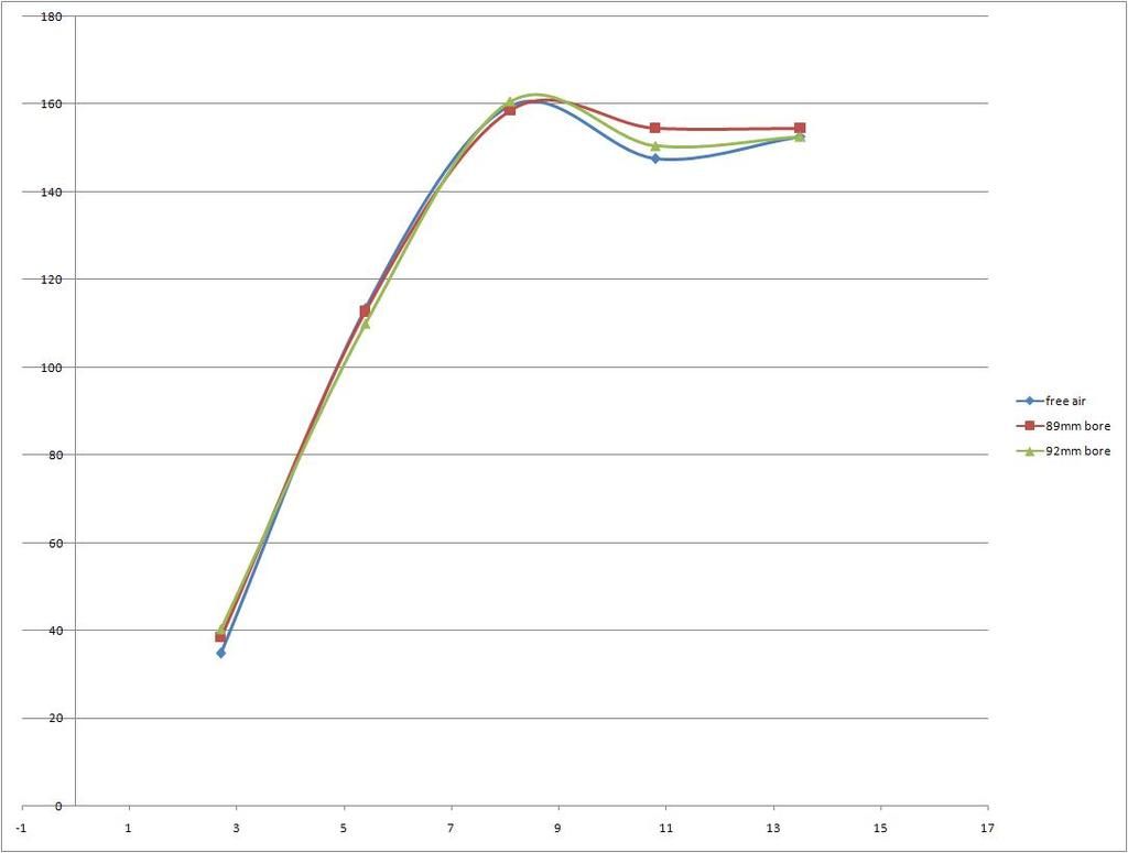
I thought I was done with the exhaust ports... However during final finishing I noticed the flow increased increased slightly which was expected, but the better the ports flow the more they drop at high lifts in flow at a certain point. Ive noticed a slight amount of loss at just above 10mm lift during all my measurements but did not pay much attention to this. No surprise the stock cam do not lift above 10mm...

So I had to do some more investigations

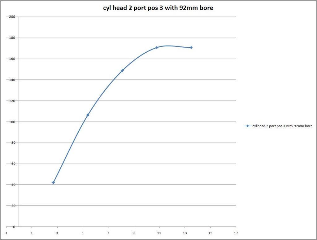
The amount of loss at these lifts are not only connected to test pressure but also which cylinder bore the heads are to be used with..
This is one of the almost finished ports tested with a infinitely large bore, 89mm bore(2.8) and 92 mm bore(3.4), the saddle point in the graph is hard to miss.


Its clear that the combination of a high lift cam, a 3.4 block and high flowing cylinder heads are going to cause some issues.

After examination of the heads I observed that the valve passes the cylinder head bottom at approx 11mm, at this position the valve disk is very close to the cylinder head edge, a 90 degree corner.
This makes perfect sense, More flow=more airspeed and with larger bore the cylinder head edge is more exposed = Interference = Turbulence = bad. That is my hypothesis.
Lets see if a solution can be found...
IP: Logged
FieroWannaBe
Member
Posts: 2289
From: USA
Registered: Oct 2004


Feedback score: N/A
Leave feedback

Rate this member

Report this Post02-28-2019 09:32 AM Click Here to See the Profile for FieroWannaBeSend a Private Message to FieroWannaBeEdit/Delete MessageReply w/QuoteDirect Link to This Post
What are you using to measure flow, a floating depression bench?
What is the actual depression, and are you using any tools to look at the flow behavior? strings, flowballs, etc?
IP: Logged
Blacktree
Member
Posts: 20770
From: Central Florida
Registered: Dec 2001


Feedback score:    (12)
Leave feedback


Total ratings: 350
Rate this member

Report this Post03-02-2019 10:36 AM Click Here to See the Profile for BlacktreeClick Here to visit Blacktree's HomePageSend a Private Message to BlacktreeEdit/Delete MessageReply w/QuoteDirect Link to This Post
 
quote
Originally posted by lordfiero:

After examination of the heads I observed that the valve passes the cylinder head bottom at approx 11mm, at this position the valve disk is very close to the cylinder head edge, a 90 degree corner.
This makes perfect sense, More flow=more airspeed and with larger bore the cylinder head edge is more exposed = Interference = Turbulence = bad. That is my hypothesis.
Lets see if a solution can be found...

Unshroud the valves?
IP: Logged
lordfiero
Member
Posts: 53
From: EU
Registered: Nov 2018


Feedback score: N/A
Leave feedback

Rate this member

Report this Post03-09-2019 12:16 PM Click Here to See the Profile for lordfieroSend a Private Message to lordfieroEdit/Delete MessageReply w/QuoteDirect Link to This Post
 
quote
Originally posted by FieroWannaBe:

What are you using to measure flow, a floating depression bench?
What is the actual depression, and are you using any tools to look at the flow behavior? strings, flowballs, etc?


Im using a flow bench consisting of 4" pipe, very large U-tube meter with water, digital velocity meter and vacuum source.
Actual measure has varied over time but now I use between 20-24" water. All graphs are corrected for 28"

No strings, but thats a good idea! I will try that some day.
IP: Logged
lordfiero
Member
Posts: 53
From: EU
Registered: Nov 2018


Feedback score: N/A
Leave feedback

Rate this member

Report this Post03-09-2019 12:32 PM Click Here to See the Profile for lordfieroSend a Private Message to lordfieroEdit/Delete MessageReply w/QuoteDirect Link to This Post

lordfiero

53 posts
Member since Nov 2018
Unshroud it is


Unfortunately it did not completely remove the weird saddle point, but after measuring all 6 exhaust ports I noticed it is not a problem with all ports, although they look identical. It may be a combination with something with the test setup.
The unshrouding did lift the top end a bit. This is what it looks like now, on the ports where i dont get the issue.


IP: Logged
lordfiero
Member
Posts: 53
From: EU
Registered: Nov 2018


Feedback score: N/A
Leave feedback

Rate this member

Report this Post03-12-2019 04:48 PM Click Here to See the Profile for lordfieroSend a Private Message to lordfieroEdit/Delete MessageReply w/QuoteDirect Link to This Post
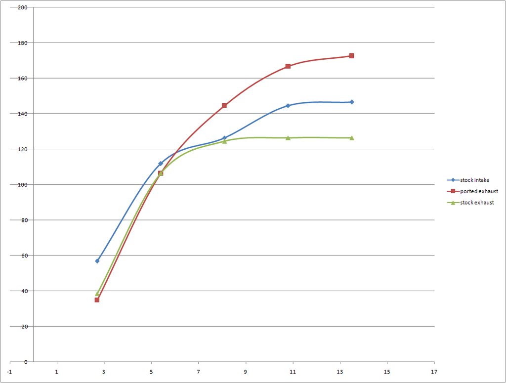
This is a comparison of the stock exhaust port, the ported one and the stock intake port. Its fun to see the modified exhaust port outflow the MUCH larger intake port by 25CFM! The stock intake port was measured to 146 CFM maxed out.


IP: Logged
lou_dias
Member
Posts: 5256
From: Warwick, RI
Registered: Jun 2000


Feedback score: (3)
Leave feedback


Total ratings: 67
Rate this member

Report this Post03-13-2019 07:45 AM Click Here to See the Profile for lou_diasSend a Private Message to lou_diasEdit/Delete MessageReply w/QuoteDirect Link to This Post
You've done amazing work to prove what *some* of us knew from real-world results!

You wouldn't believe the trolls that came out of the wood-works when I posted a 187 rwhp / 249 ft*lbs Mustang dyno with my 3.4 using the ported Fiero intake, heads and 2.5" exhaust using the stock 3400 roller cam... Now, La Fiera is posting >250 rwhp dynos on Mustang dynos with custom cams and custom intake.

[This message has been edited by lou_dias (edited 03-13-2019).]

IP: Logged
Notorio
Member
Posts: 2964
From: Temecula, CA
Registered: Oct 2003


Feedback score: (3)
Leave feedback

Rate this member

Report this Post03-13-2019 06:23 PM Click Here to See the Profile for NotorioSend a Private Message to NotorioEdit/Delete MessageReply w/QuoteDirect Link to This Post
Just curious as to your flow bench set up. If you have built a DIY can you share any details?
IP: Logged
PFF
System Bot
Will
Member
Posts: 14219
From: Where you least expect me
Registered: Jun 2000


Feedback score: (1)
Leave feedback


Total ratings: 237
Rate this member

Report this Post03-14-2019 09:17 AM Click Here to See the Profile for WillSend a Private Message to WillEdit/Delete MessageReply w/QuoteDirect Link to This Post
 
quote
Originally posted by lou_dias:

You've done amazing work to prove what *some* of us knew from real-world results!

You wouldn't believe the trolls that came out of the wood-works when I posted a 187 rwhp / 249 ft*lbs Mustang dyno with my 3.4 using the ported Fiero intake, heads and 2.5" exhaust using the stock 3400 roller cam... Now, La Fiera is posting >250 rwhp dynos on Mustang dynos with custom cams and custom intake.


Is he? If he's posted a dyno sheet, I missed it.
IP: Logged
lordfiero
Member
Posts: 53
From: EU
Registered: Nov 2018


Feedback score: N/A
Leave feedback

Rate this member

Report this Post03-16-2019 07:54 AM Click Here to See the Profile for lordfieroSend a Private Message to lordfieroEdit/Delete MessageReply w/QuoteDirect Link to This Post
 
quote
Originally posted by Notorio:

Just curious as to your flow bench set up. If you have built a DIY can you share any details?


Still adjusting the flow set up but it follows the principles found if you google, but I try to catch some of it if I photo more. Im focused on the engine build right now
If youre intrested in building one you can start with an adjustable vacuum source and a U-tube. You will get similar results by just checking pressure loss through the test object and you also see if you have enough power for generating correct pressures.


Thank you Lou
I cant see any problems in generating same power levels/cui in these engines as any other pushrod GM engine since the 60s to now, they are all the same. One nice thing with the 60V6 is the compact size and relatively low weight. Its just harder work (and more fun) to get there due to less performance parts available.

[This message has been edited by lordfiero (edited 03-16-2019).]

IP: Logged
lou_dias
Member
Posts: 5256
From: Warwick, RI
Registered: Jun 2000


Feedback score: (3)
Leave feedback


Total ratings: 67
Rate this member

Report this Post03-23-2019 01:02 PM Click Here to See the Profile for lou_diasSend a Private Message to lou_diasEdit/Delete MessageReply w/QuoteDirect Link to This Post
Looking forward to the build. Before you dyno it remember this:
Use STOCK WHEELS !!!
I took a lot of heat from trolls for my dyno sheets because I kept losing power. Most of my dyno's coincided with using a larger/heavier wheel+tire combination so the net result was that my dyno numbers consistently went down. It was a lesson I learned years later.
My current wheel+tire weight is 52 lbs (325x35/17). I still put down over 200 ft*lbs and almost 170 rwhp but the struggle is real. All my weight gain is on the perimeter.

IP: Logged
La fiera
Member
Posts: 2194
From: Mooresville, NC
Registered: Jun 2008


Feedback score:    (7)
Leave feedback

Rate this member

Report this Post03-23-2019 08:40 PM Click Here to See the Profile for La fieraSend a Private Message to La fieraEdit/Delete MessageReply w/QuoteDirect Link to This Post
 
quote
Originally posted by Will:


Is he? If he's posted a dyno sheet, I missed it.

IP: Logged
lou_dias
Member
Posts: 5256
From: Warwick, RI
Registered: Jun 2000


Feedback score: (3)
Leave feedback


Total ratings: 67
Rate this member

Report this Post03-24-2019 10:51 AM Click Here to See the Profile for lou_diasSend a Private Message to lou_diasEdit/Delete MessageReply w/QuoteDirect Link to This Post
 
quote
Originally posted by La fiera:


<3
IP: Logged
La fiera
Member
Posts: 2194
From: Mooresville, NC
Registered: Jun 2008


Feedback score:    (7)
Leave feedback

Rate this member

Report this Post03-24-2019 07:37 PM Click Here to See the Profile for La fieraSend a Private Message to La fieraEdit/Delete MessageReply w/QuoteDirect Link to This Post
 
quote
Originally posted by lordfiero:

I cant see any problems in generating same power levels/cui in these engines as any other pushrod GM engine since the 60s to now, they are all the same. One nice thing with the 60V6 is the compact size and relatively low weight. Its just harder work (and more fun) to get there due to less performance parts available.


Ya' man!!!

IP: Logged
Will
Member
Posts: 14219
From: Where you least expect me
Registered: Jun 2000


Feedback score: (1)
Leave feedback


Total ratings: 237
Rate this member

Report this Post03-25-2019 07:11 AM Click Here to See the Profile for WillSend a Private Message to WillEdit/Delete MessageReply w/QuoteDirect Link to This Post
 
quote
Originally posted by La fiera:


Where's the rest?

Looks like 245 and 5900 RPM to me...

Good work on it.
IP: Logged
lou_dias
Member
Posts: 5256
From: Warwick, RI
Registered: Jun 2000


Feedback score: (3)
Leave feedback


Total ratings: 67
Rate this member

Report this Post03-25-2019 08:10 AM Click Here to See the Profile for lou_diasSend a Private Message to lou_diasEdit/Delete MessageReply w/QuoteDirect Link to This Post
The best Mustang dyno in my area still reports 5% lower than Dynojet dynos... so even at 5900 that's >257 rwhp on a dynojet in my book..

Also notice the "date". ;-)

[This message has been edited by lou_dias (edited 03-25-2019).]

IP: Logged
La fiera
Member
Posts: 2194
From: Mooresville, NC
Registered: Jun 2008


Feedback score:    (7)
Leave feedback

Rate this member

Report this Post03-25-2019 08:48 AM Click Here to See the Profile for La fieraSend a Private Message to La fieraEdit/Delete MessageReply w/QuoteDirect Link to This Post
 
quote
Originally posted by Will:


Where's the rest?

Looks like 245 and 5900 RPM to me...

Good work on it.


You are right WIll, that was 245WHP AT 5900rpm.
But just Look how straight the red line is. It laid out 252WHP @ 6200rpm.
Called it quits at 252 when I discovered the stock pump didn't have enough
flow to keep the fuel rails filled as the injectors emptied them at high rpm.
So, there's more to come at you Will!

[This message has been edited by La fiera (edited 03-25-2019).]

IP: Logged
Will
Member
Posts: 14219
From: Where you least expect me
Registered: Jun 2000


Feedback score: (1)
Leave feedback


Total ratings: 237
Rate this member

Report this Post03-26-2019 08:33 AM Click Here to See the Profile for WillSend a Private Message to WillEdit/Delete MessageReply w/QuoteDirect Link to This Post
Bam!
IP: Logged
PFF
System Bot
lordfiero
Member
Posts: 53
From: EU
Registered: Nov 2018


Feedback score: N/A
Leave feedback

Rate this member

Report this Post03-26-2019 04:43 PM Click Here to See the Profile for lordfieroSend a Private Message to lordfieroEdit/Delete MessageReply w/QuoteDirect Link to This Post
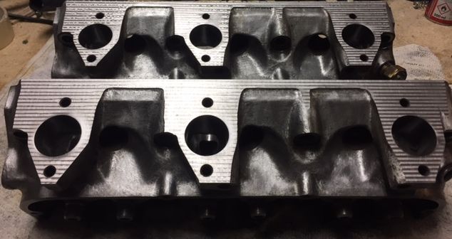
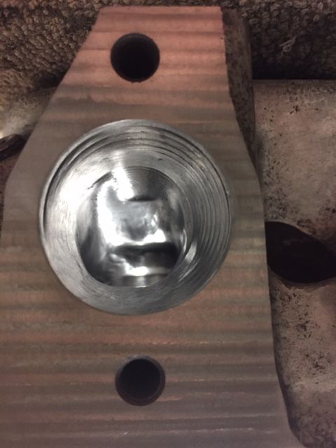
The stock intake port can flow ok if there is no turbulence in the transition between port to intake manifold, or to the surrounding air in my test case. However, the air divider do reduce the port area, and a large area is the most important factor for high flow.
A very large area will reduce the air speed to much and may lead to fuel separates from being suspended in the air stream, according to theory. I do not believe this will ever be a problem with this cylinder head, the port size is designed for a low rpm 2.8 and there is not that much metal to remove. So I started the grinder

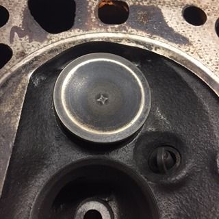
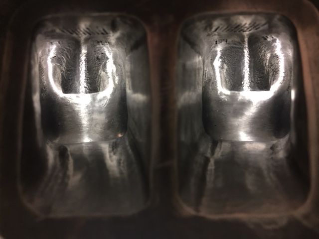
I tried a few different sizes of shark fins and also tested to make the valleys next to the fin deeper.

Shark fin


After the shark fin test I removed the air divider completely and then started to make the port slightly larger in a few steps.

Flat bottom


and yes, there is no gasket matching done on the pictures, yet.
IP: Logged
lordfiero
Member
Posts: 53
From: EU
Registered: Nov 2018


Feedback score: N/A
Leave feedback

Rate this member

Report this Post03-26-2019 05:21 PM Click Here to See the Profile for lordfieroSend a Private Message to lordfieroEdit/Delete MessageReply w/QuoteDirect Link to This Post

lordfiero

53 posts
Member since Nov 2018
lou: cool picture!
IP: Logged
lordfiero
Member
Posts: 53
From: EU
Registered: Nov 2018


Feedback score: N/A
Leave feedback

Rate this member

Report this Post04-01-2019 03:42 PM Click Here to See the Profile for lordfieroSend a Private Message to lordfieroEdit/Delete MessageReply w/QuoteDirect Link to This Post
After some grinding the heads looks like this...

Very nice and shiny


close up on the exhaust runner
IP: Logged
Blacktree
Member
Posts: 20770
From: Central Florida
Registered: Dec 2001


Feedback score:    (12)
Leave feedback


Total ratings: 350
Rate this member

Report this Post04-01-2019 04:30 PM Click Here to See the Profile for BlacktreeClick Here to visit Blacktree's HomePageSend a Private Message to BlacktreeEdit/Delete MessageReply w/QuoteDirect Link to This Post
According to the Chevy Power manual, that fin in the intake port increases flow by about 17%. Did your testing suggest otherwise?
IP: Logged
lordfiero
Member
Posts: 53
From: EU
Registered: Nov 2018


Feedback score: N/A
Leave feedback

Rate this member

Report this Post04-02-2019 06:50 PM Click Here to See the Profile for lordfieroSend a Private Message to lordfieroEdit/Delete MessageReply w/QuoteDirect Link to This Post
 
quote
Originally posted by Blacktree:

According to the Chevy Power manual, that fin in the intake port increases flow by about 17%. Did your testing suggest otherwise?


Yes I also read that one. Its hard to say.. I did not find any advantages with the stock shape compared to the flat floor, at least if you lower the floor sligthly at the same time as removing the air divider.
Another annoying thing, the air divider gets in the way of the tools needed to work with the porting.
I do not get any specific gains from making the air divider into a shark fin either. You may gain some in one end but loose in the other.

But Im still working on measuring the different ports..
IP: Logged
lou_dias
Member
Posts: 5256
From: Warwick, RI
Registered: Jun 2000


Feedback score: (3)
Leave feedback


Total ratings: 67
Rate this member

Report this Post04-03-2019 09:39 AM Click Here to See the Profile for lou_diasSend a Private Message to lou_diasEdit/Delete MessageReply w/QuoteDirect Link to This Post
Too me, the fin was there to balance the pressure. IIRC there is a dibit on the opposite wall so the air at the front of the stem would go up the down and then also split the flow around the sides evenly. So perhaps it's not something that shows up on a water-based test.

This is one of those things where "water" and air flow differently... Air compresses. Water does not. Hence balancing air pressure is a thing.
IP: Logged
lordfiero
Member
Posts: 53
From: EU
Registered: Nov 2018


Feedback score: N/A
Leave feedback

Rate this member

Report this Post04-04-2019 04:35 PM Click Here to See the Profile for lordfieroSend a Private Message to lordfieroEdit/Delete MessageReply w/QuoteDirect Link to This Post
I think the stock shape is pretty good. The flow limit is likely to be the very sharp knee of the port design and it is hard to fix that.

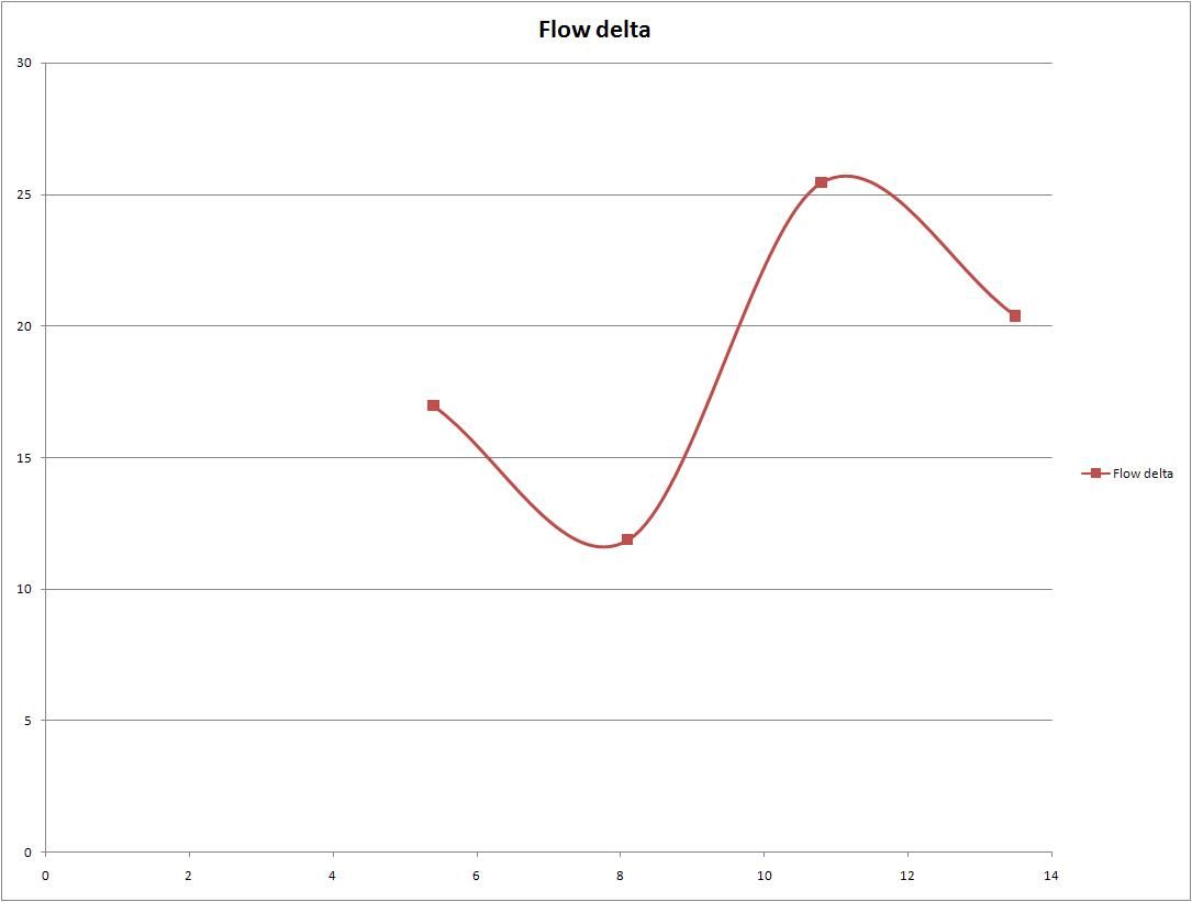
Ended up with this design which gives a healthy gain in flow


This is the difference in flow between a stock port and the ports above. Positive gain through the valve lift range with more than 25CFM peak improvement.


I have also added som needed power to the flow bench, above 6kW, so I measure directly at 28" water now. this gives better results.
IP: Logged
La fiera
Member
Posts: 2194
From: Mooresville, NC
Registered: Jun 2008


Feedback score:    (7)
Leave feedback

Rate this member

Report this Post04-05-2019 09:31 PM Click Here to See the Profile for La fieraSend a Private Message to La fieraEdit/Delete MessageReply w/QuoteDirect Link to This Post
Like Will would say, BAM!!

IP: Logged
lordfiero
Member
Posts: 53
From: EU
Registered: Nov 2018


Feedback score: N/A
Leave feedback

Rate this member

Report this Post04-14-2019 01:29 PM Click Here to See the Profile for lordfieroSend a Private Message to lordfieroEdit/Delete MessageReply w/QuoteDirect Link to This Post
Bam

Very similar, you took a little more on the valve guides. Who needs alu heads
IP: Logged
Previous Page | Next Page

This topic is 3 pages long:  1   2   3 
next newest topic | next oldest topic

All times are ET (US)

Post New Topic  Post A Reply
Hop to:

Contact Us | Back To Main Page

Advertizing on PFF | Fiero Parts Vendors
PFF Merchandise | Fiero Gallery | Ogre's Cave
Real-Time Chat | Fiero Related Auctions on eBay


Copyright (c) 1999, C. Pennock