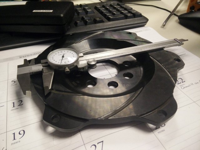
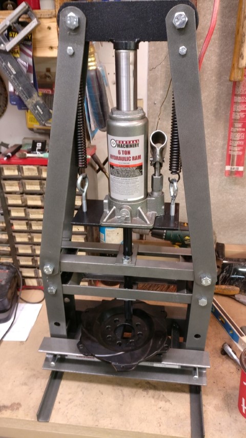
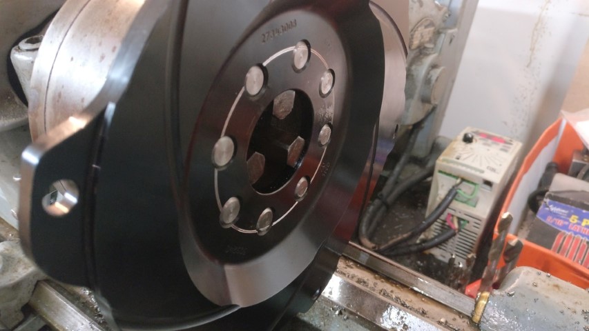
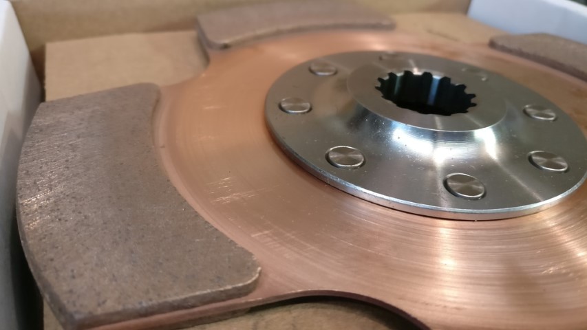
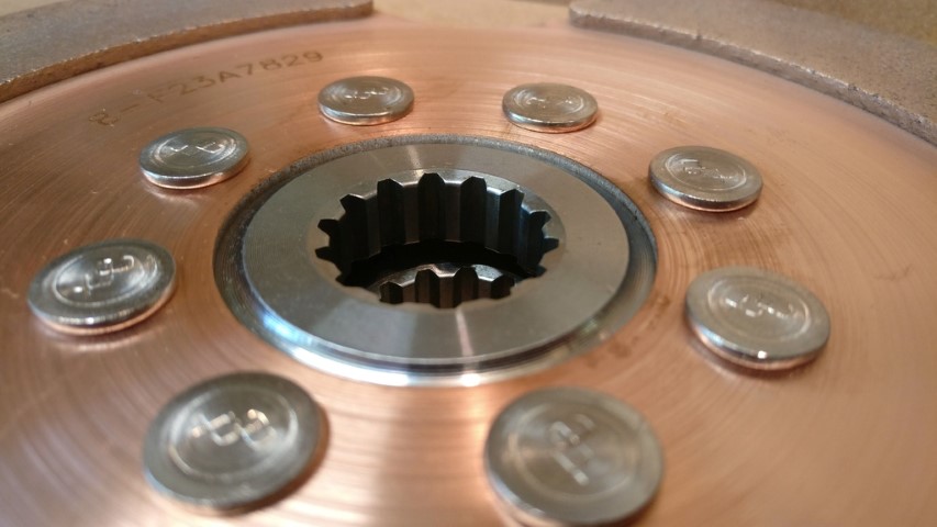
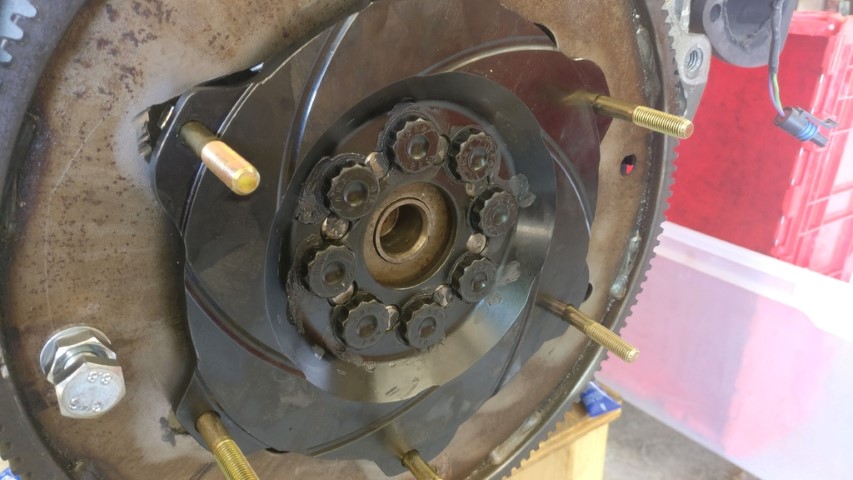
Something I've been working on for the past few weeks. The flywheel is a QuarterMaster button unit for a Mopar R5/P7 application; their NASCAR motor. I went with that flywheel because it was ridiculously cheap ($40) and it had an 8-bolt pattern . Knowing that I'd have to drill the new pattern, I plugged the old one with annealed 4140 plugs that I machined .005" oversized. I pressed them in along with LocTite sleeve retainer just for peace of mind. Then I drilled the new pattern.
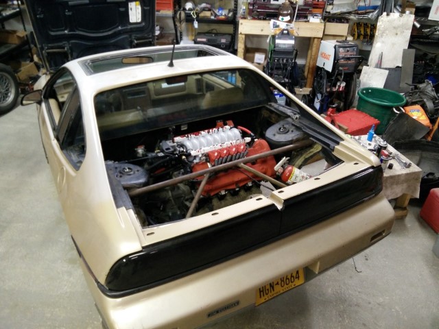
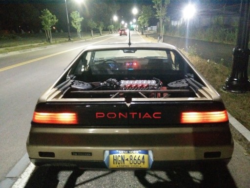
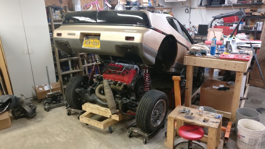
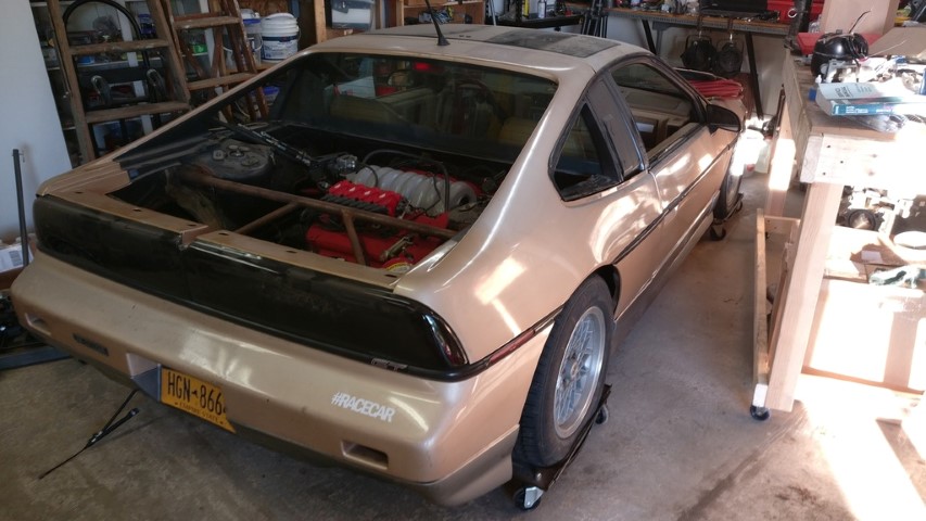
Anyway, first the car;
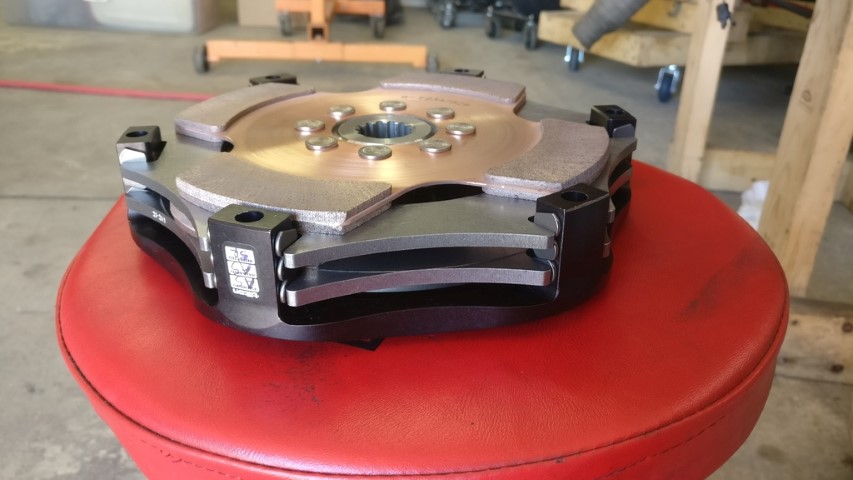
...and the flywheel;
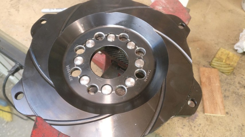
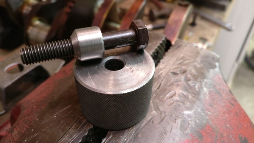
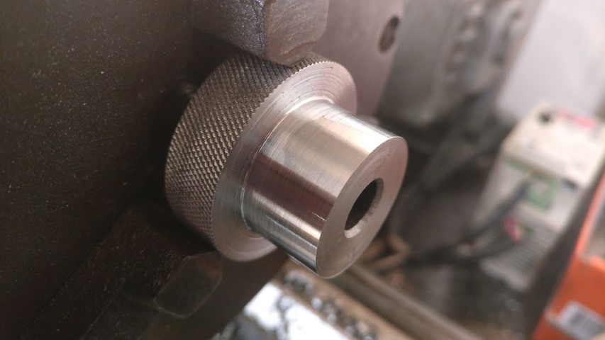
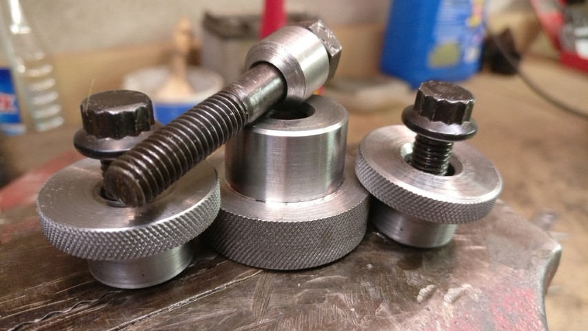
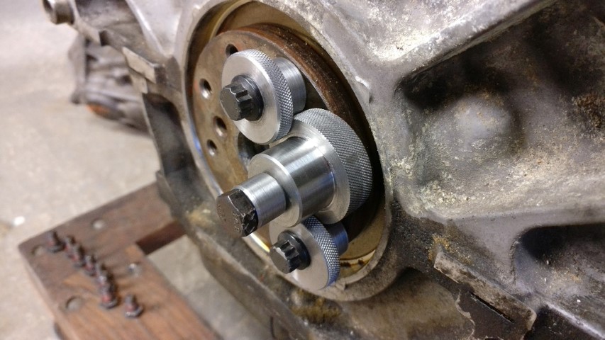
Flywheel's done. I'll be stacking it on top of the factory flexplate for starting purposes. I've gotten Ford Coyote M10x1.0mm flywheel bolts so that I can have real flywheel bolts instead of the GM M8x1.25mm garbage. I've been working on jigs to redrill the crank snout, but I haven't quite finished yet. I have, however, finished the drill bit guide along with it's centering pilot.
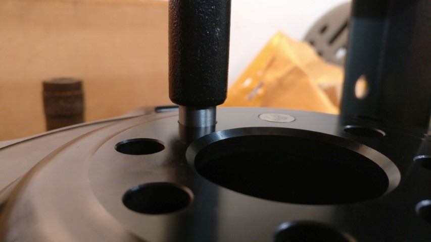
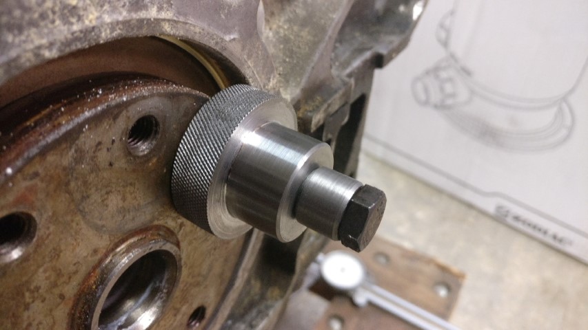
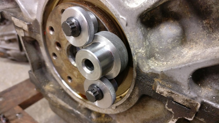
So basically, I'll use the two adjacent bolt holes with mirrored shouldered washers to clamp against the shoulder on the guide, then remove the centering pilot. Nice and concentric drill bit guide clamped firmly to the flange. So then I just drill and tap with a tap guide [that I have yet to make].
This is basically where I've left off. I need to make those clamping washers and stop collars for both the drill bit and tap and then modify the flange on my 'new' motor.
[This message has been edited by 1986 Fiero GT (edited 10-02-2021).]
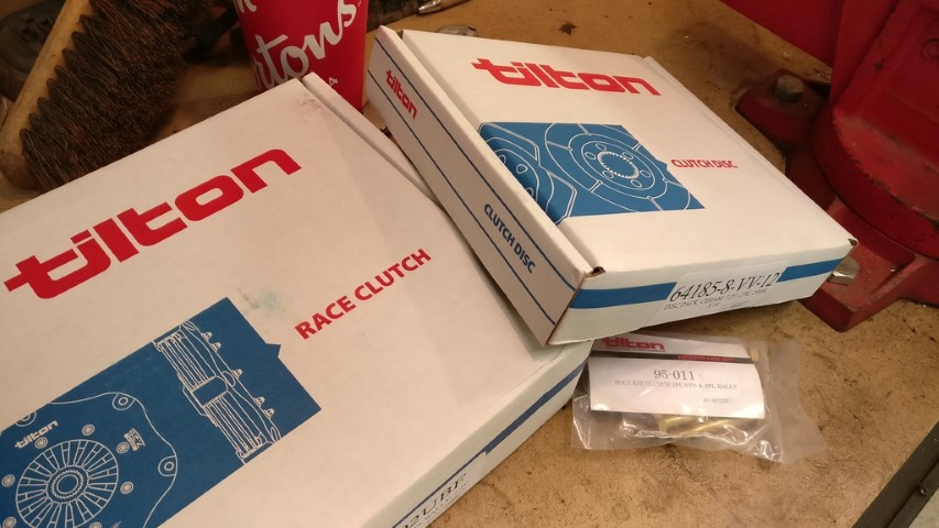
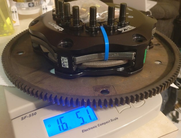
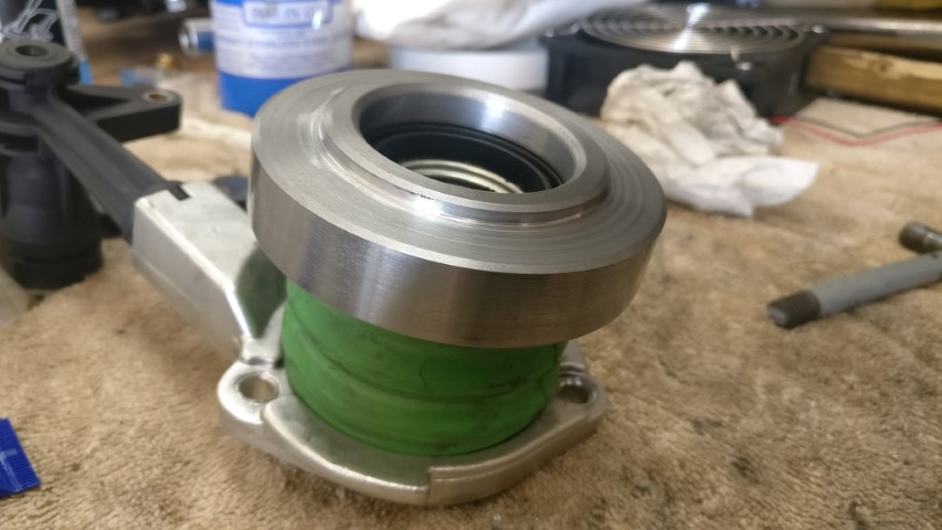
Oh, and I do have the clutch. It's absolutely glorious. I went with the Ultra High ratio pressure plate for modulation, along with the Buff springs. Translation? 570ft./lb. holding capacity.
...and the best part? This is the entire assembly including ALL hardware.
[This message has been edited by 1986 Fiero GT (edited 10-02-2021).]
Probably don't, really. I just wanted to. Much the same way that I hate wheels with two patterns, I didn't want my flywheel to be Swiss cheese. It's not such a fiddly job on a neutral balance flywheel with a symmetrical bolt pattern.
Did you verify the stack height to make sure everything will fit within the F23? What are you doing about the throwout bearing - typically the 7 1/4 pressure plates need a smaller diameter throwout bearing face to work best?
I am interested to hear how the drivability is, When I add a turbo, I will likely need to upgrade my current clutch setup. They guys running an organic disk say they are easy to over heat and typically get about 15000 miles before it needs to be replaced. The guys running the metallic disks have commented about them being grabby. So I am curious as to wear yours falls in the spectrum. I would suspect some of the 9" twin disk setups would have better drivability (but more mass and MOI).
I would have pressed in the plugs as well, but then simply offset the hole pattern on top of the current one (drilling part of the hole through the new plugs). This would maximize the virgin material between the bolt holes and with the plugs, the head of the bolts would be fully supported.
Did you verify the stack height to make sure everything will fit within the F23? What are you doing about the throwout bearing - typically the 7 1/4 pressure plates need a smaller diameter throwout bearing face to work best?
I am interested to hear how the drivability is, When I add a turbo, I will likely need to upgrade my current clutch setup. They guys running an organic disk say they are easy to over heat and typically get about 15000 miles before it needs to be replaced. The guys running the metallic disks have commented about them being grabby. So I am curious as to wear yours falls in the spectrum. I would suspect some of the 9" twin disk setups would have better drivability (but more mass and MOI).
There's plenty of room in the F23 housing. Something like almost an inch more depth than a 282. I actually think I've got about a .250"-.375" gap between the diaphram fingers and throwout. What I'm going to do is machine an adapter to go on the face of the throwout that will take up the extra distance as well as give me the 44mm 'ring' that Tilton recommends to release the diaphram spring. I have to disassemble my F23 to reseal it anyhow, so I'll use the bellhousing half to take my measurements while I'm waiting for that.
The discs I got are the cerametallic discs. They claim 570ft./lb. holding capacity with the UH ratio pressure plate and Buff springs. I went with the UH ratio plate because it was recommended for modulation, which is what you want in a street car. We'll see how it goes, but I wouldn't even be upset about 15,000-20,000 miles out of it. That's like 2 or 3 seasons for me. Probably take me half a day to swap clutch discs at this point.
I installed a Tilton 5/8" master cylinder up front when I did the F23 install, so I shouldn't have to worry about any hydraulic issues with this setup. I'm expecting it to be up to twice as still, but I'm okay with that as the previous setup was basically a mild-mannered factory GM setup.
[This message has been edited by 1986 Fiero GT (edited 05-14-2017).]
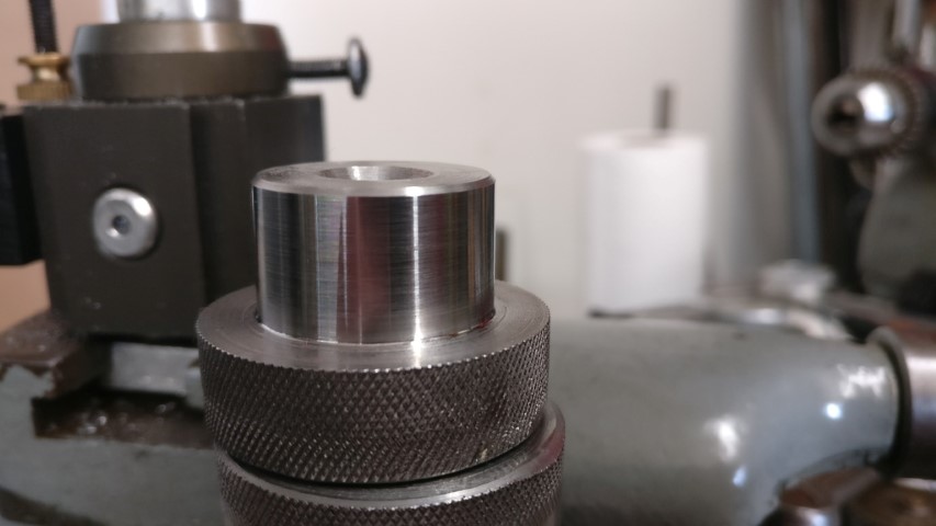
Basically, I bolt the drill guide to the flange with the long M8 bolt and centering sleeve. Then, I bolt the clamps on with either M8 or M10 bolts depending on whether I've modified that hole yet or not. Then just drill and tap. Tomorrow I'm hoping to get over to the shop and make my flywheel centering pilot and a guide to make sure the tap is perpendicular and straight.
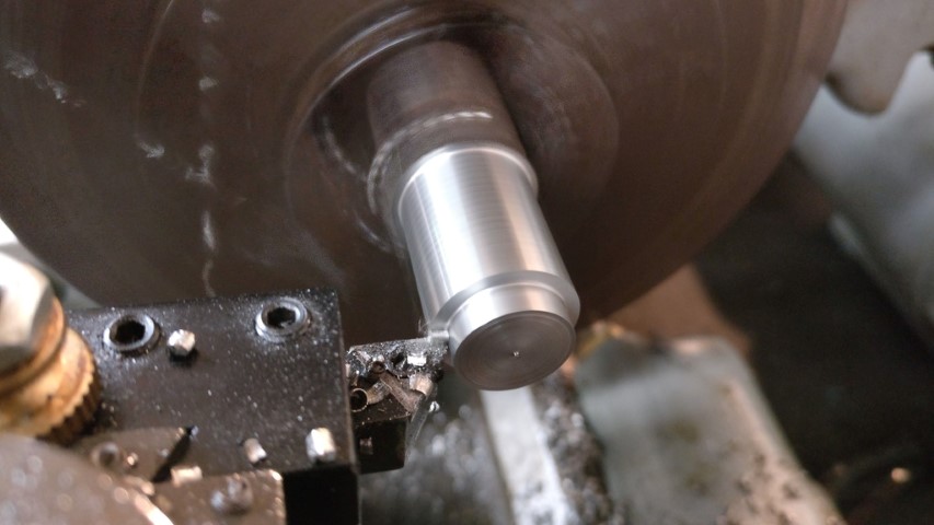
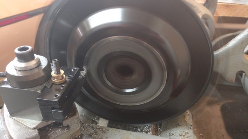
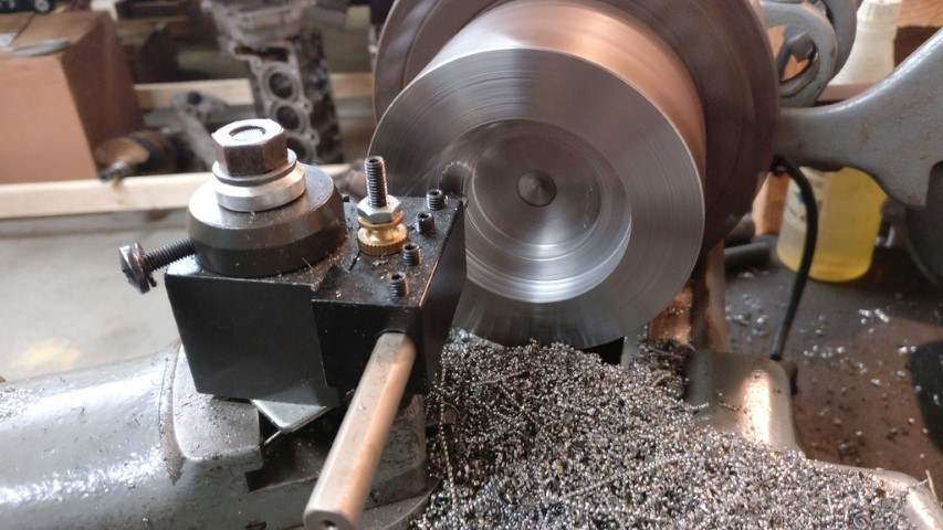
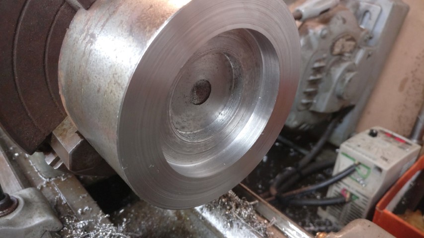
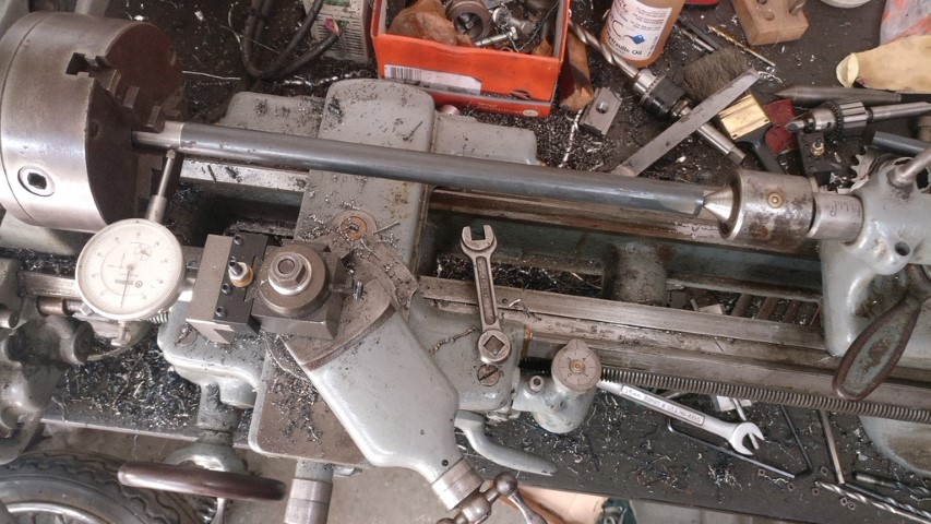
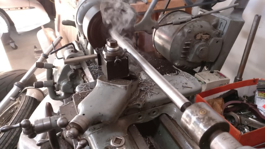
Getting pretty decent with this lathe. Beautiful surface finish, here.
[This message has been edited by 1986 Fiero GT (edited 10-02-2021).]
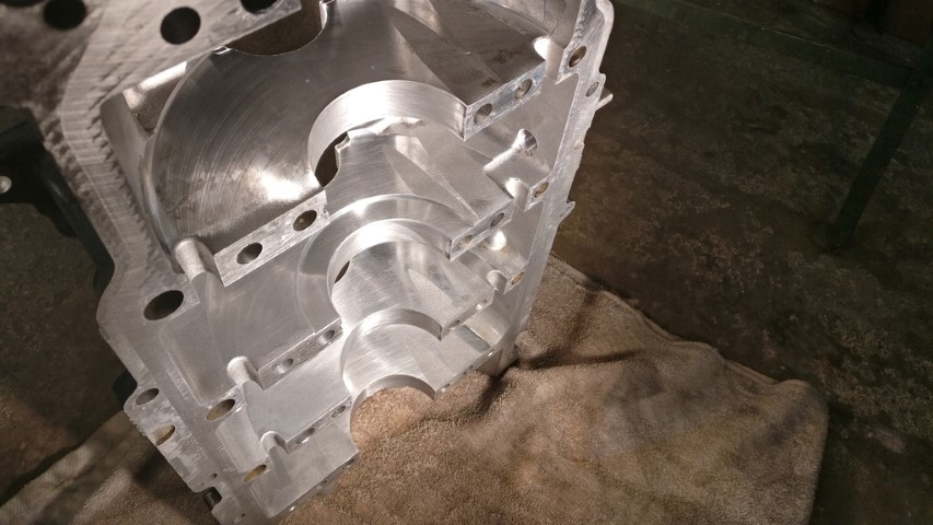
If anybody is still following along, I managed to drill and tap the crankshaft in my 'new' motor. Seems like it'll work just fine.
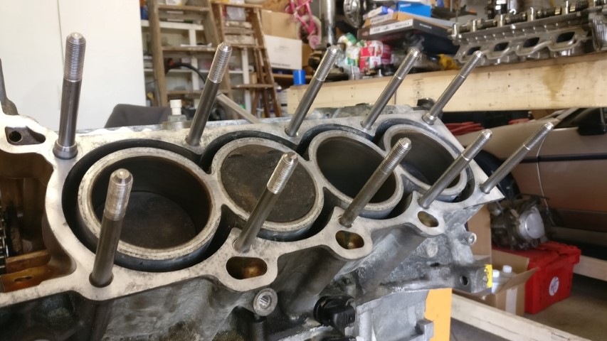
Gonna head over on Sunday to reseal the motor halves and fix the head bolts with Northstar Performance studs. I DO NOT recommend him. I had an extremely poor experience and will never be back. Having said that, I'm more than capable of machining my own 4140 inserts and using ARP studs from now on. That solution is even cheaper than his. I must give him credit for his tooling, though. It works great.
[This message has been edited by 1986 Fiero GT (edited 10-02-2021).]
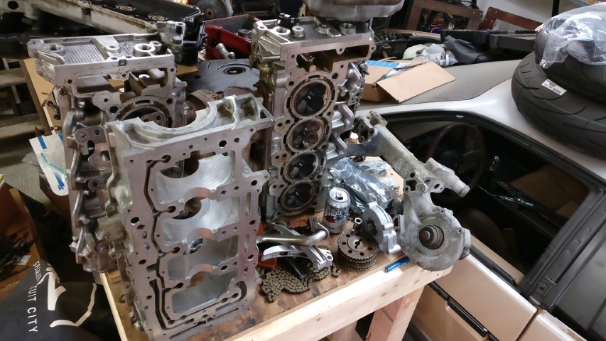
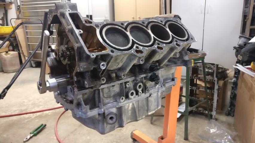
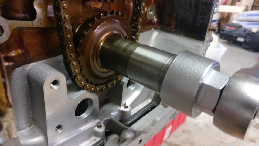
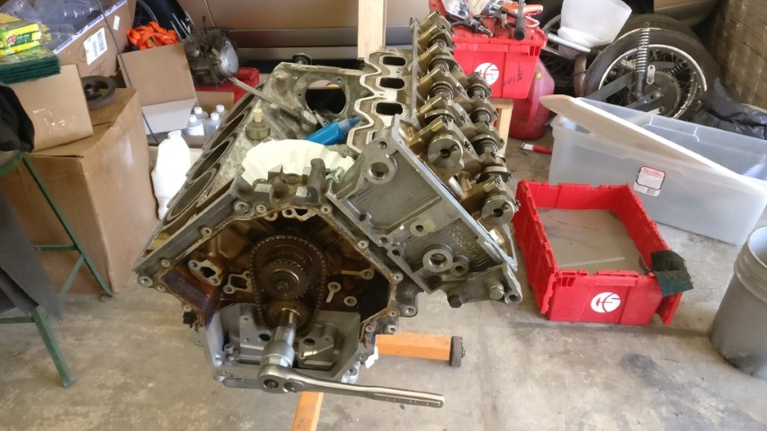
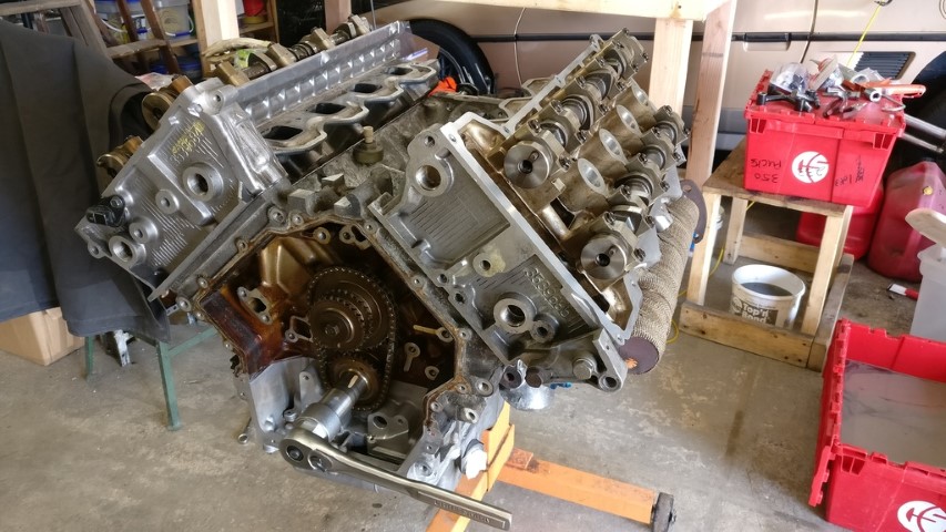
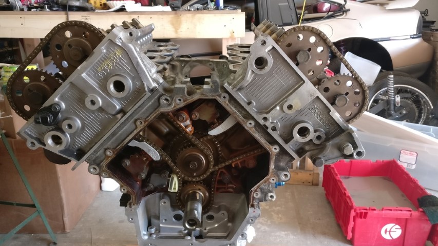
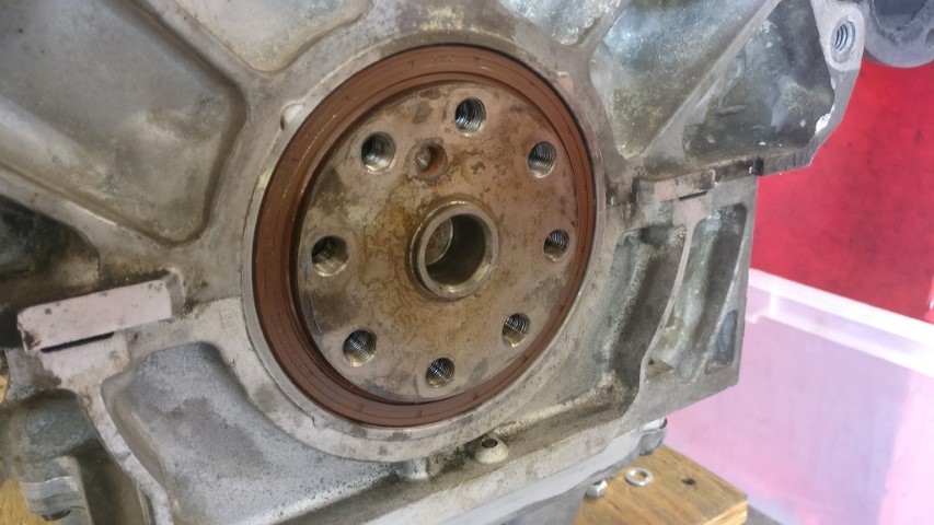
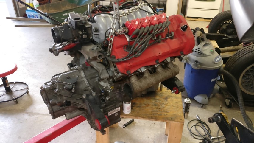
I tore the motor down for resealing and head bolt repair after modifying the crank flange, so I'm now putting it back together.
The contrast of the fully degreased bottom crankcase half and oil-varnished upper block is kind of funny to me.
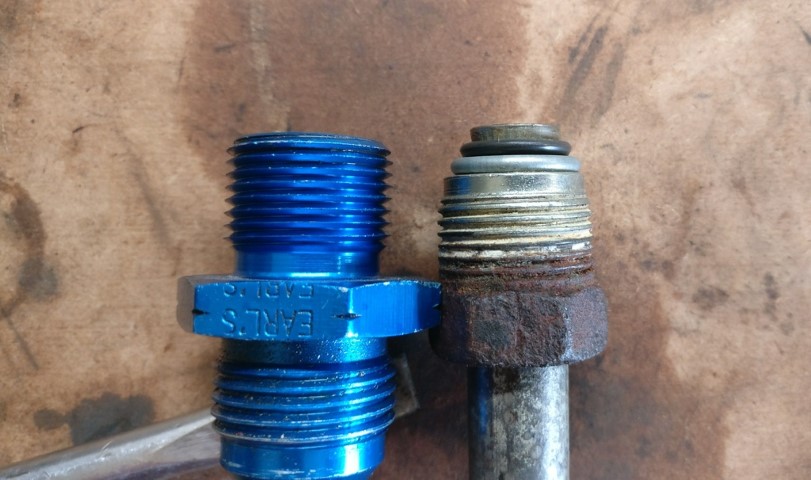
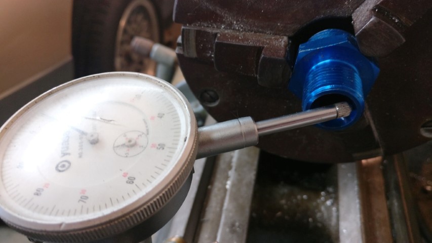
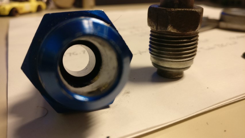
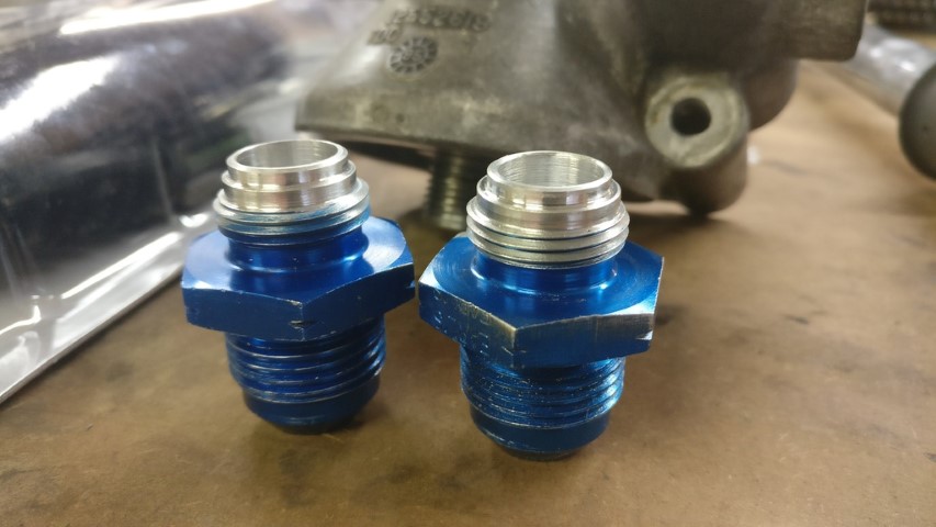
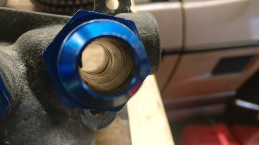
I'm noticing a few small things that I'm modifying as I go along as well. For example, take something as simple as the oil cooler fittings that go into the filter housing ports. I had to turn down the tips of the fittings to gain a 'shoulder' to put some RTV around so as to seal the fitting in the bore. I also decided to bore the fitting out, as there was a pointless restriction in the fitting reducing cross-sectional area by what must have been at least 30%.
Much better. I'm hoping to get the rest of the bottom end reassembled and fix the head bolts sometime this week. I'd like to have the long block ready this weekend so that I can focus on getting the clutch assembled. After I get the clutch assembled on the motor I can measure for the throwout bearing adapter/spacer. Might have this thing back together next week.
[This message has been edited by 1986 Fiero GT (edited 10-02-2021).]
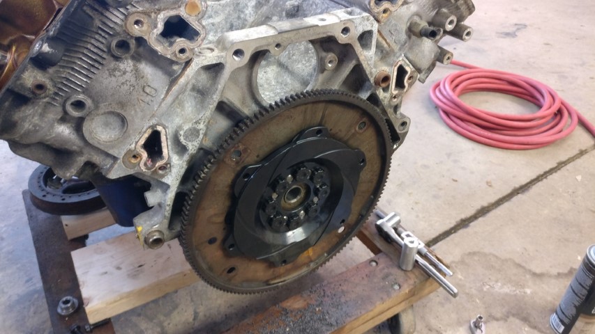
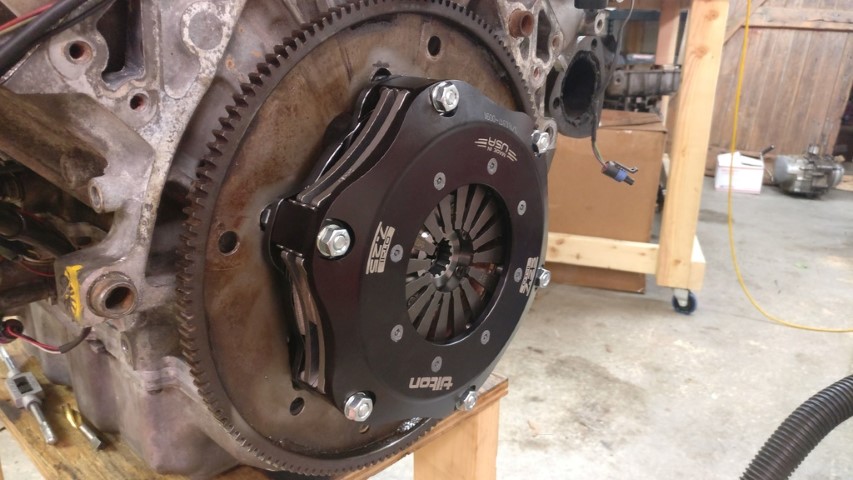
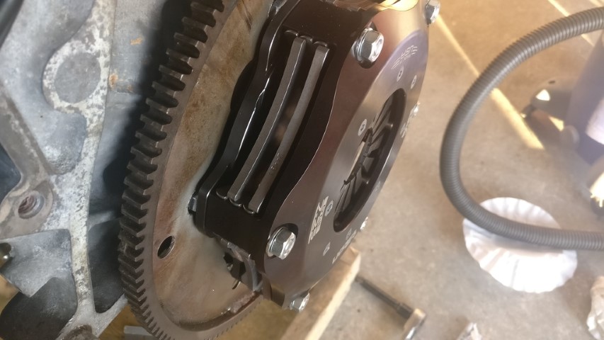
So then I started working on getting the clutch assembled so that I could take the measurements for my throwout adapter/spacer.
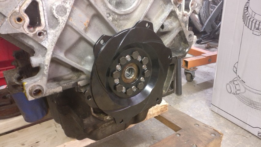
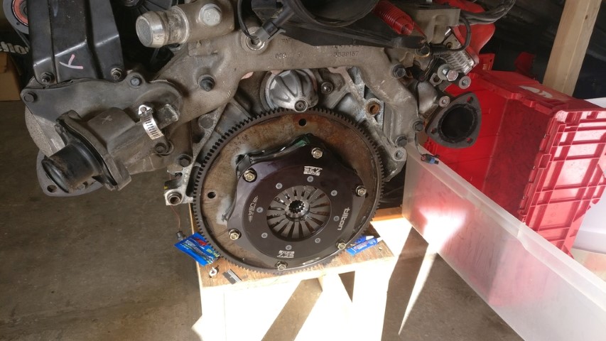
Ended up having to take a bunch of time to make clearance holes in the flexplate for the bolt heads behind the flywheel holding the clutch cover on. Finally got it assembled, though.
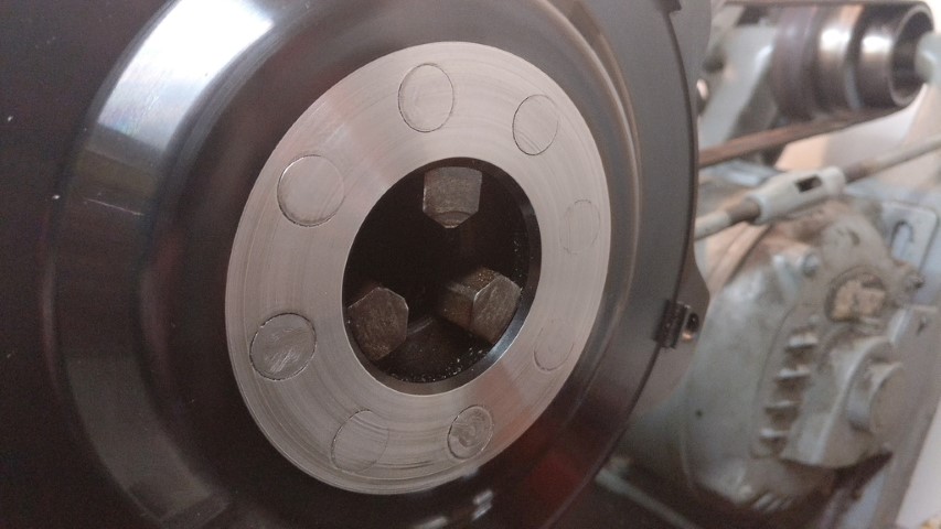
Everything looks pretty damn concentric. Looks like I haven't screwed up too badly yet.
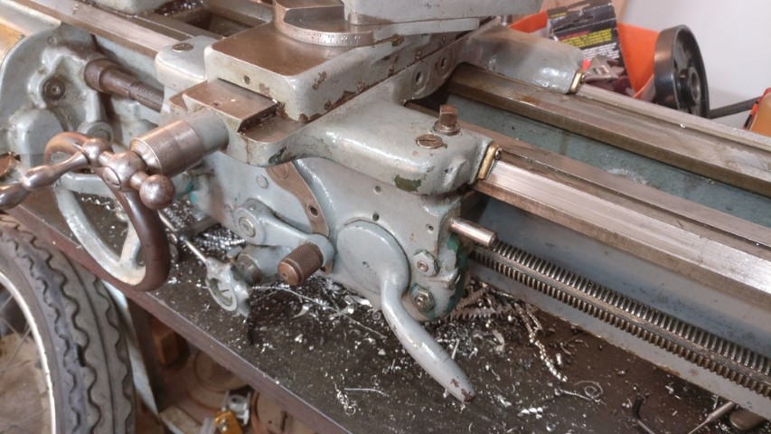
Hoping to rebuild the apron in my lathe tomorrow so that I can more easily make that throwout adapter and the parts for my fuel rails.
[This message has been edited by 1986 Fiero GT (edited 10-02-2021).]
Does the F23 have a deeper bellhousing than the 282?
In looking at all the measurements for the Tilton 7.25" into to the 282 bellhousing, I found there wasn't enough available clearance to stack a button flywheel on top of a flex plate.
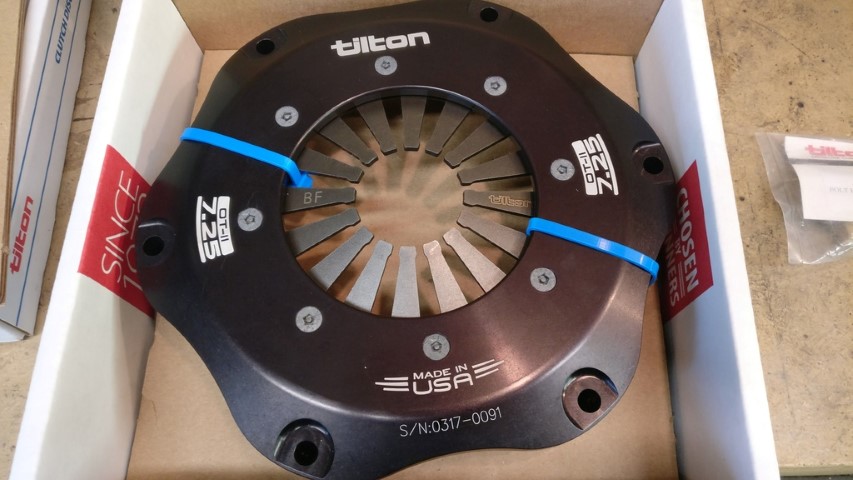
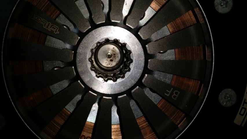
The limitation was contact between the inner ring of screws--where it looks like you now have flat heads--and the output shaft bearing boss. I was expecting to turn the screws over so the heads were on the outside instead of the nuts. That bought me some clearance. Switching to flat heads as you've done would buy more. I'd have to have the unit in my hands to evaluate how good an idea I thought that would be, however. I'd probably be more inclined to counterbore the pressure plate cover and keep the hex head screws instead of going to flat heads. I might even slot the counterbores on a mill to keep the screws from turning. Interesting idea.
There's something like .500"+ more bellhousing depth in the F23 than the 282. My F23 is split again right now because it was leaking after I reassembled it, so I took the opportunity to tap just the bellhousing onto the motor and visualize the depth from the HTOB bore to the diaphragm fingers. With the HTOB fully compressed, I've got an almost .500" gap between the bearing and the fingers. Enough room for the thickness of the 44mm adapter and the .170" - .230" initial clearance for wear that Tilton recommends.
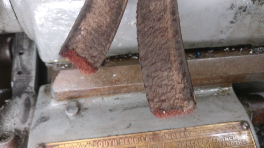
Hoping to head back over tonight to reassemble my South Bend and take some more measurements for all of this. I'll try to take a few more pictures.
The limitation was contact between the inner ring of screws--where it looks like you now have flat heads--and the output shaft bearing boss. I was expecting to turn the screws over so the heads were on the outside instead of the nuts. That bought me some clearance. Switching to flat heads as you've done would buy more.
Just realized this, but I'm guessing you're talking about the 8 screws along the interior diameter that hold the diaphragm spring? For what it's worth, that's the way my clutch cover came directly from Tilton. I didn't have to change any hardware. They look like countersunk security pentalobe screws. They really don't want you to take it apart yourself, apparently.
Just realized this, but I'm guessing you're talking about the 8 screws along the interior diameter that hold the diaphragm spring? For what it's worth, that's the way my clutch cover came directly from Tilton. I didn't have to change any hardware. They look like countersunk security pentalobe screws. They really don't want you to take it apart yourself, apparently.
Yes, those are the screws to which I was referring. It's been a few years since I did my work; I guess they updated the design. That's great, as it gives me an extra 3/32" or so to add to the button thickness since I won't have to allow for those bolt heads. It'll still require me to hollow out a flex plate and weld it to the OD of the button, but now I won't be pushing minimum thicknesses for the flywheel bolt head clamping locations or the threaded bosses for the PP cover bolts... at least not pushing them as hard as I was.
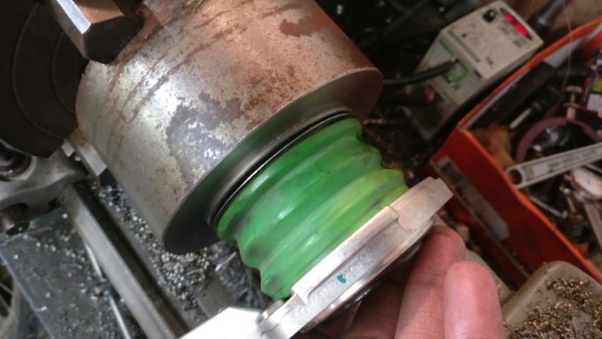
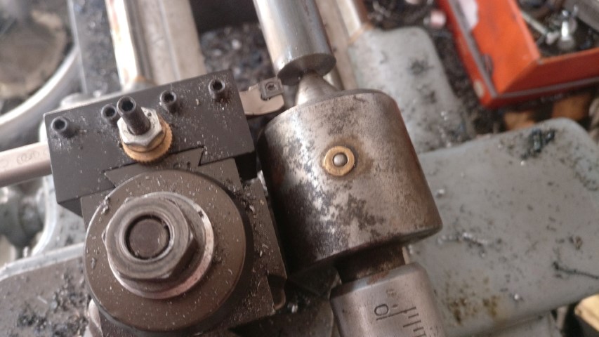
I put that lathe back together the other day and started working on that throwout adapter.
I was struggling to get further. Turning the ID and counterbore the other day wasn't too bad. Today when trying to turn the OD, the machine didn't seem to have much power, surface finish was gummy and it chewed up the three inserts I had left right away. I ended up doing some research and discovering that I was spinning the spindle too slowly to get the recommended ~600SFM for 4140PH, which is like 30-32rc and I wasn't cutting as quickly as recommended. At this point all that I had left was a boring bar with CCMT inserts and I started using that. Actually worked pretty well, until the ancient leather belt snapped.
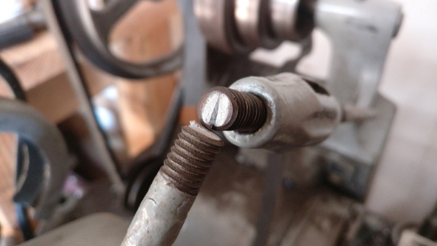
So, I measured for a new belt and set out to PepBoys for the belt and some bypass caps. They seemed to be the only local-ish store to stock them. Anyway, belt was too long. Hah. Great. So, I cut it and stitched it together with fishing line. Now, when I tried to tension the belt with the lever, it kept spring back and relieving tension. I couldn't understand why, until about the third time I applied the lever and the tensioning rod snapped.
Damn. Guess that's what I get for trying to actually use a 65 year old lathe.
So, I think I'll get some 3/8" rod in the morning, then bend and thread it to replace at least the broken portion. I do have a 3/8-16 right hand die; I do not have a 3/8-16 left hand die. That'll have to wait until I can get a hold of one. Then hopefully I can fix the belt and get it back up and running. I need this machine to finish this throwout adapter and injector bungs for my new rails.
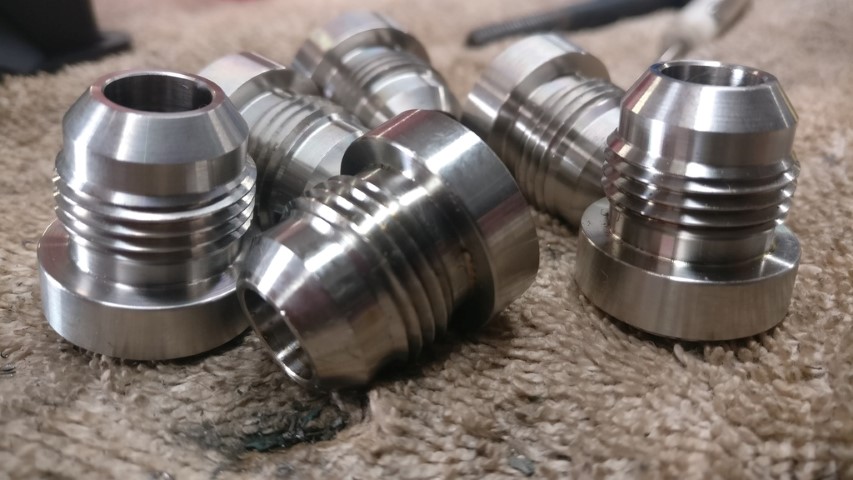
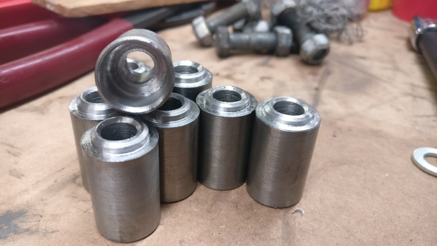
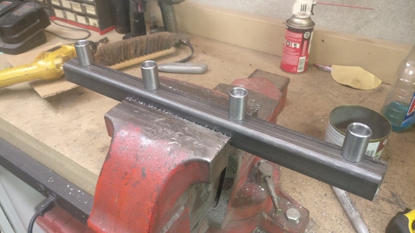
Speaking of bungs, check these beauties out. They were like $3 apiece shipped. Couldn't make 'em for that.
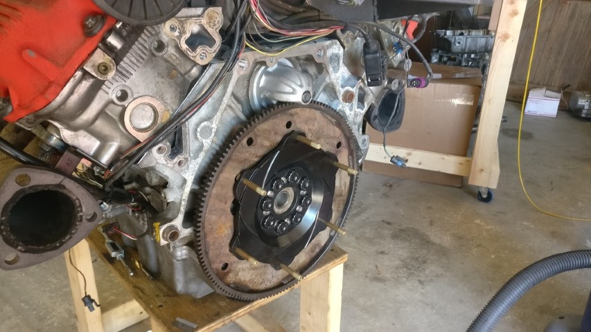
Anyway, I managed to get the flywheel and clutch fully assembled and torqued down with LocTite, ready to go.
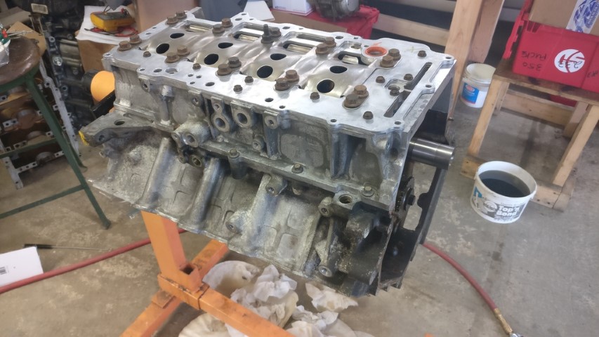
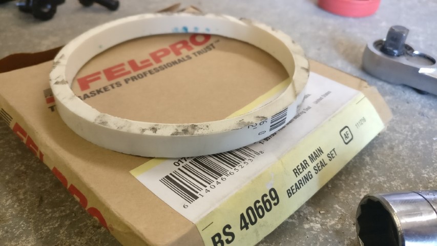
Nice, new rear main seal went in first with that fancy white tool.
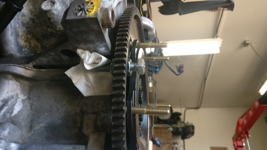
Then I assembled the flexplate and flywheel with the ARP hardware, red LocTite on the threads and UltraTorque lube under the heads. I finagled a pretty decent crankshaft locking tool and put the flywheel bolts at 70ft/lbs, the clutch cover.bolts went to 18ft/lbs.
And everything all torqued down with the water crossover back on the heads and block.
If I can get that lathe back together tomorrow, I might still have the motor back in the car this weekend.
[This message has been edited by 1986 Fiero GT (edited 10-02-2021).]
Looks good, that N* water pump setup looks like a PITA to work around.
------------------ "I am not what you so glibly call to be a civilized man. I have broken with society for reasons which I alone am able to appreciate. I am therefore not subject to it's stupid laws, and I ask you to never allude to them in my presence again."
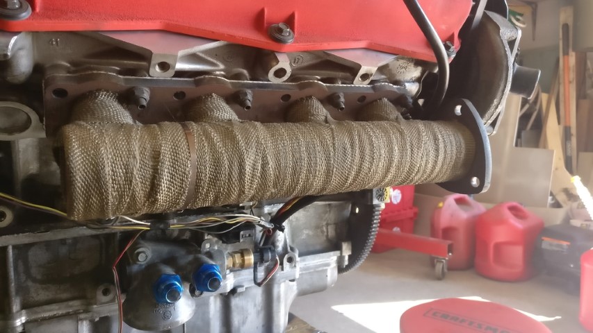
I've got no large complaints about the water crossover on the back of the motor. It does cover the factory fluid fill/vent cap on the F23, so I use the VSS to fill the fluid when the trans is attached to the motor. I will say that I hated it for a while when I was trying to bleed the the coolant in the first motor last summer. I didn't realize that one had garbage head gaskets, so when I was trying to get it bled; I kept seeing bubbles. Then it hit me. Steady bubbles means bad head gaskets. Anyway, once I got the heads fixed on the first motor; I didn't have any further water crossover issues. Even the water larg-ish pump is tucked away nicely at the end of the 'front' head. I'm pretty sure I could change a belt or probably even the pump itself with the motor in the car. I can even get at my forward bank of spark plugs without moving or removing anything
I ended up buying Northstar Performance studs [pictured above] with which to repair the thing. I do not recommend him. The guy is extremely defensive and quick with an excuse when you confront him and frankly, he's kind of a dick and he takes forever to ship anything. Completely ignored my pleading requests to expedite shipping. From the day I placed my order to the day I had the heads back on the motor was something like 5 weeks. From now on I'll either buy or make the 5/8"-11 X M11x1.5 inserts and use ARP studs. Heck, that method is still cheaper than his studs provided you've already got or are capable of making the tooling. None of it is really rocket science.
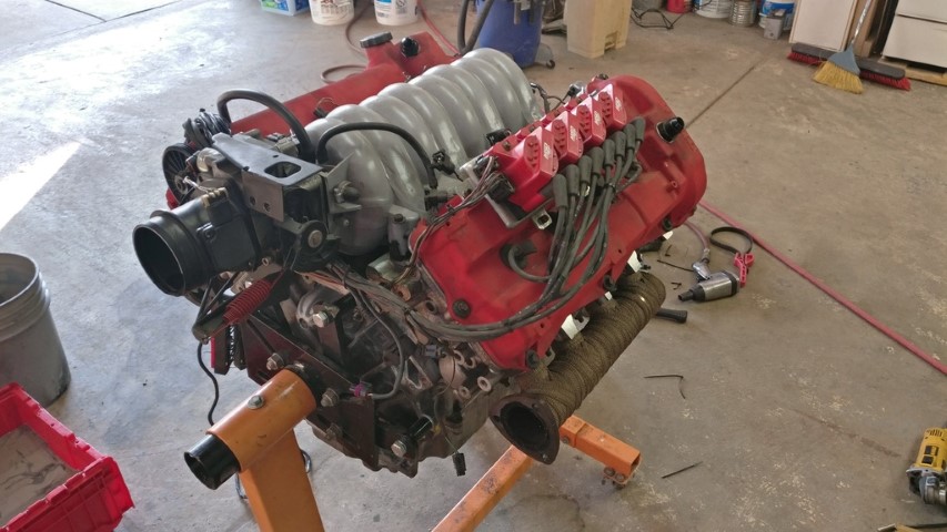
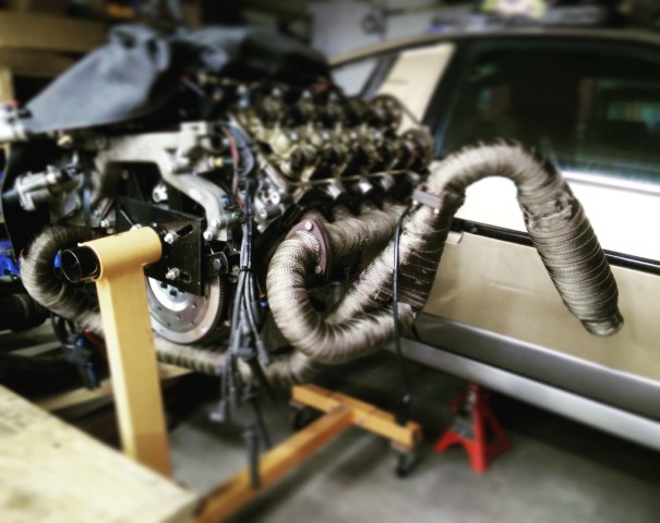
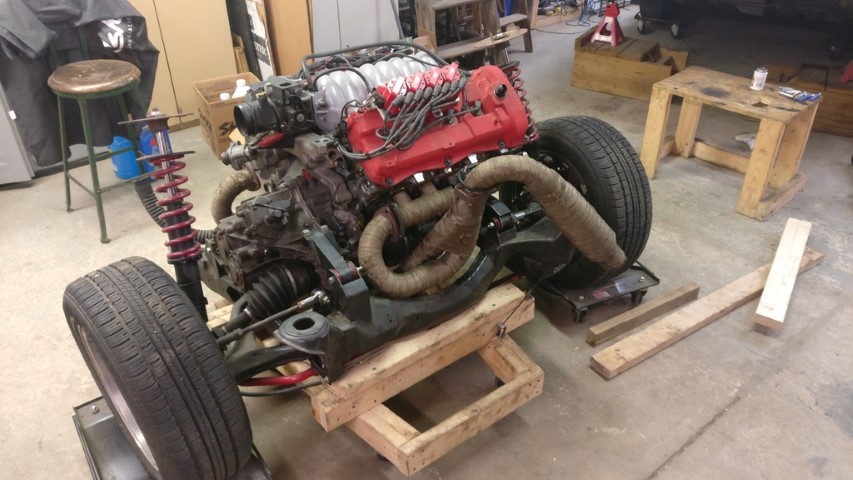
This is where I ended up after the weekend.
Just need to actually bolt the cradle back in, reattach the hoses, wire and cables and fill the fluids. Oh, and whittle up that new set up fuel rails real quick. I should be able to handle that in about a day or two.
[This message has been edited by 1986 Fiero GT (edited 10-02-2021).]
It's interesting that all the product photos on Tilton's website still show the style assembled with screws from the inside and nuts on the outside, rather than the flatheads like yours has. I guess I'll have to include that in my conversation with a sales rep when I order.
It's interesting that all the product photos on Tilton's website still show the style assembled with screws from the inside and nuts on the outside, rather than the flatheads like yours has. I guess I'll have to include that in my conversation with a sales rep when I order.
Maybe it was a recent change and their literature/artwork doesn't reflect this? Like I said, those countersunk security pentalobe screws were provided by them and I'm pretty grateful for it. Comparing the two sets of hardware; I'm not sure that it would be a clearance issue for me so much as you, but it's definitely a conversation to have with your Tilton rep. I bet that would be quicker than ordering through Summit. I ended up ordering the wrong clutch cover bolts and it took like 27 or 28 days to even ship. Oh well. I'm still pretty happy, pending first drive.
what are you doing about your left rear toe link? it looks like your new rear transmission mount is in the way of the mounting perch.
quote
Originally posted by Will:
For some purposes it is. The 282's external throw out arm only clears the water manifold after some judicious grinding.
OTOH, having the waterpump on the back end is what lets the engine fit into a Fiero in the first place.
I think if I were to do a N* swap, I would run a remote pump, I don't like waterpumps being run off of timing chains.
------------------ "I am not what you so glibly call to be a civilized man. I have broken with society for reasons which I alone am able to appreciate. I am therefore not subject to it's stupid laws, and I ask you to never allude to them in my presence again."
There aren't any issues with the lateral links. The inboard mounts have been relocated and changed to heim joints.
Waterpump isn't driven off of the timing chain. It's belt driven off of front (left) bank intake cam. There's nothing to worry about there. Everything fits fine and there's even a hose that basically fits perfectly for the drivers side coolant tube.
[This message has been edited by 1986 Fiero GT (edited 10-02-2021).]
There aren't any issues with the lateral links. The inboard mounts have been relocated and changed to heim joints.
Waterpump isn't driven off if the timing chain. It's belt driven off of front (left) bank intake cam. There's nothing to worry about there. Everything fits fine and there's even a hose that basically fits perfectly for the drivers side coolant tube.
10-4 on the links, on the water pump, the timing chain still carries the load, of the pump, which is the part I don't like, I'm sure it can handle it, but I prefer to separate the loads.
10-4 on the links, on the water pump, the timing chain still carries the load, of the pump, which is the part I don't like, I'm sure it can handle it, but I prefer to separate the loads.
Aah, now I see what you're saying as far as loading the timing chain is concerned. Never really thought that far up the driveline.
It's tough to replace the water crossover on this motor with something, and you can't simply just pull the pump out and bypass everything. CHRFab makes adapters that will allow you to run AN hose from each input and output from the block and heads (four total) back to a custom Meziere pump with a built-in thermostat housing. The built-in thermostat is the key there after you remove the water crossover. Anyway, it'll cost you at least $1,000. At least.
These motors run for 100K with even no maintenance. If you replace the chain tensioners, water pump belt and tensioner; you'd never have problems.
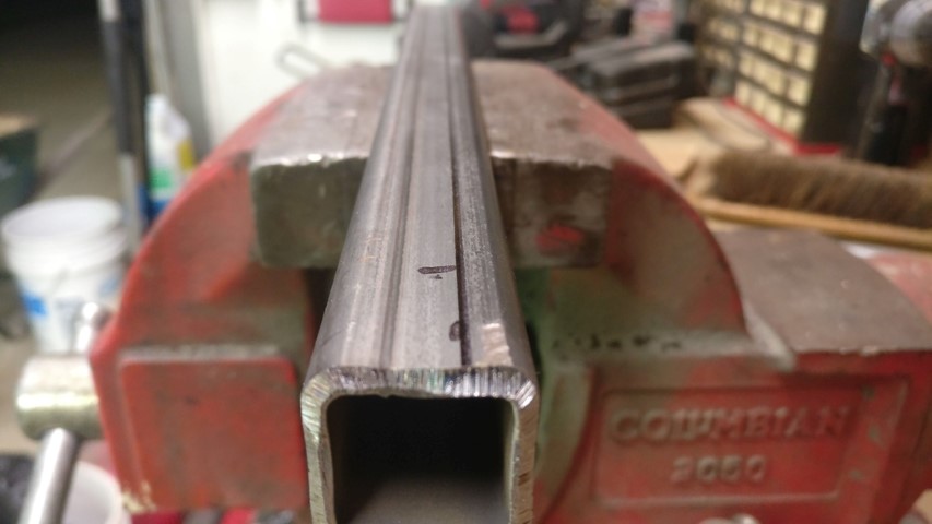
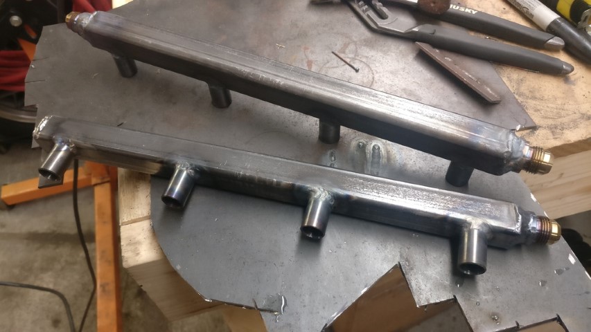
These are to replace the set that I made last year. I learned a few things while making them and I wanted to put those things into effect to improve the second set.
I center drilled both ends of some .750" A36 rod and then turned about an inch of one end until it was straight. I then indicated it. I obviously did all of this in the 3-jaw, so ultimate precision clearly wasn't much of a factor.
So now I've got a nice and long piece of straight round stock at what turned out to be .670" diameter.
I decided to make the new bungs 1" long in order to space the rail a bit further from the intake. The injectors are ever-so-slightly angled inward to spray directly into the head, so a bit more length will give me more clearance for tools to tighten the retaining hardware. I had problems with that on the first rails. I also learned on the first set of rails that I should start with a smaller overall bore [5/16"], with a .545" counterbore for the injector at .450" deep. I used the smaller overall bore because the injector bore itself is rather small, and I gain a bunch more metal for machining a shoulder into the top of the bung for positive location in the rail as well as making the bung thicker for better/easier weld penetration and less deformation. All things I learned last time.
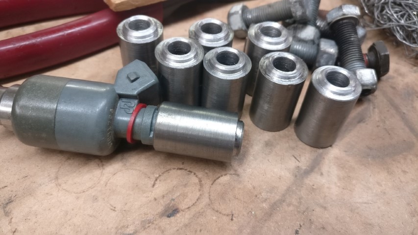
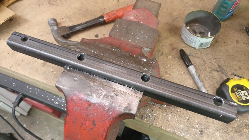
So I worked on drilling the rails. I re-measured the injector spacing this time by measuring with the calipers across the injector bores at the closest points [3.465"]. I then measured the diameter of the injector bore [.540"] and added the two together to get center-to-center bore spacing. That's 4.005" if you're paying attention. So, 4" bore spacing for all intents and purposes.
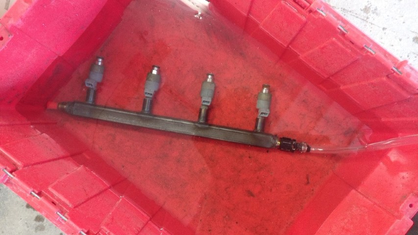
So I cut 14" rails and drilled them, with the holes offset toward the outside of the rail for further hardware/tool clearance.
...and of course I set the bungs on top to get a look and take some measurements.
Pretty beauty, eh?
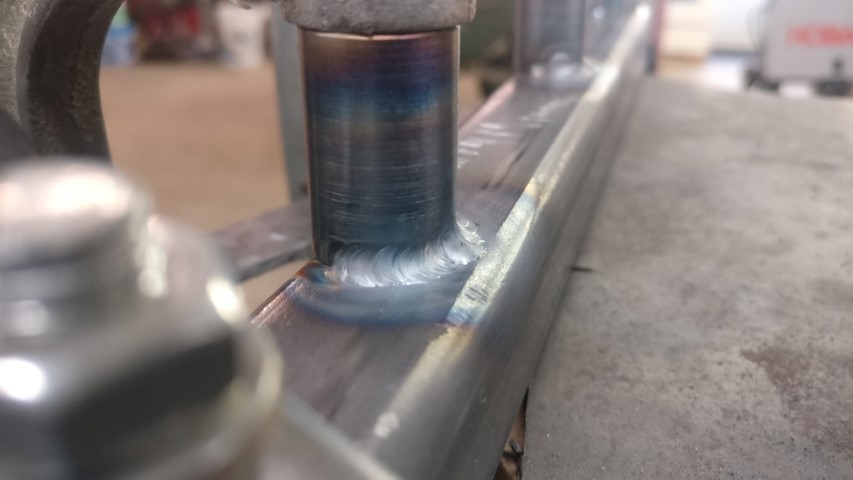
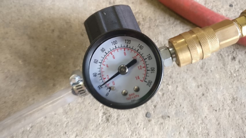
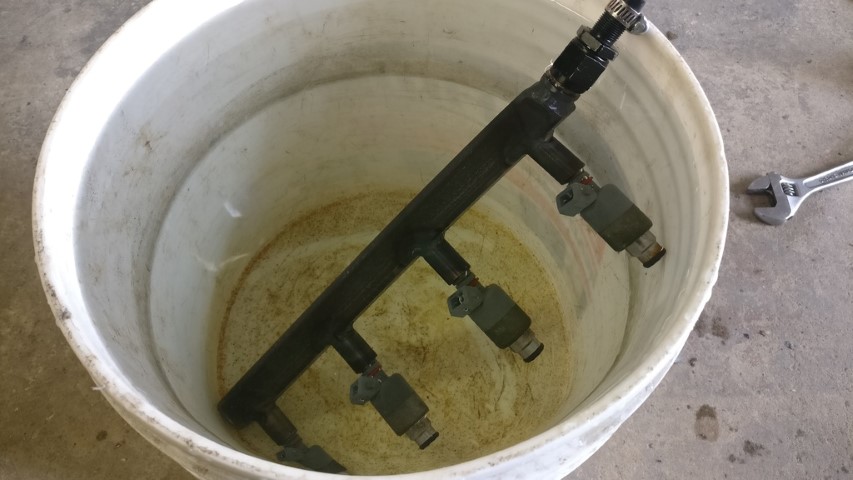
I didn't get a change to weld anything, so Saturday morning will have to do. I'm working all day tomorrow. Hopefully I can get over there early enough to weld them, pressure test them and get at least a couple coats of paint on them by early morning.
[This message has been edited by 1986 Fiero GT (edited 10-02-2021).]
10-4 on the links, on the water pump, the timing chain still carries the load, of the pump, which is the part I don't like, I'm sure it can handle it, but I prefer to separate the loads.
It's a non-issue. Lots of engines drive the waterpump off the timing drive. The Quad 4 does, AND drives the PS pump off the back of the intake cam. The Ferrari 3.4 V8 drives the waterpump off the back of the timing belt. Suzuki Reno and everything else that uses that engine (which is a GM engine) does as well. And that's just the engines I've seen.
Damn. I was close. Sometimes I forget that everything on this motor is metric. Which I kinda love. So, 102mm is 4.015". I was .010" off. I'll take it. Hah.
Is that spec in the service manual somewhere? I have one for a '98 Deville or something Northy-equipped and I just noticed the other day that they provide the threads and dimensions for every single hole in the block and heads for thread repair. Amazing. That book might be the best $20 purchase ever.
I don't think I've ever seen it in print. After all, a mechanic doesn't need to know that to tear the engine down, time-sert a bolt hole and reassemble it.
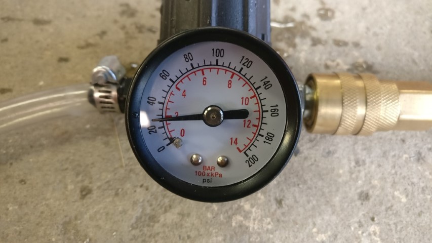
Hoping to get over there tonight to pressure test and get a coat or two of paint on them. Also hoping to fill the engine and transmission with fluids and see if she'll build oil pressure.
[This message has been edited by 1986 Fiero GT (edited 10-02-2021).]
Not a single bubble from either. Almost couldn't believe it. I still need to fab and attach some mounting brackets and get a couple coats of paint on them. That's tomorrow, hopefully.
I filled the transmission and engine with oil. Since the water crossover covers the fill cap, I had to improvise and fill through the VSS hole. I put ~2.5 quarts in and none seemed to be leaking out, so that's good. Also, there must be two sizes of dipstick for these motors, because the one that I have does not touch the oil in the pan. There is a full 8 quarts in there, what with the filter and oil cooler. There is no way the oil wouldn't be on the dipstick if I had the proper length one. I did a bit of Googling and found references to both a 23" and 28.5" stick. Of course, I have a 23" one. Tomorrow I'm hoping to finish up some loose ends; like bleeding the brakes, hooking up the parking brake and emptying the fuel tank of last summer's stale fuel. Not much left to do. I put the battery on a Tender so I can see if it'll build oil pressure tomorrow. Wouldn't crank today.
[This message has been edited by 1986 Fiero GT (edited 10-02-2021).]